Note : Les descriptions sont présentées dans la langue officielle dans laquelle elles ont été soumises.
CA 02833020 2013-11-13
TEMPORARY SUPPORT
BACKGROUND
This disclosure relates to the temporary support of signs and of other
equipment, such as
electrical equipment, especially floodlights, above the ground.
There are numerous circumstances where signs or other equipment, especially
electrical
equipment of different kinds, needs temporarily to be mounted on a support
above the ground.
Examples include temporary traffic signs or signals, public address speakers
at a country show or for
a travelling circus, satellite dishes for military communication, emergency
lighting for roadworks,
and temporary floodlights for emergency workers at the site of an accident or
for sporting fixtures
played after dark or in poor lighting conditions, especially on public
grounds.
While there have been numerous prior proposals for temporary supports for
signs and for
electrical and other equipment, mostly in the form of mechanically connectable
structures, the
structures proposed have often suffered from being too complicated to be
readily erectable and
demountable by a single person unfamiliar with the structure, too bulky when
collapsed to be
readily transportable, for example in the boot (trunk) of a small car
(automobile), or insufficiently
stable.
As will become clear from the detailed description below, the present
disclosure
adopts a different approach.
SUMMARY OF THE INVENTION
In accordance with a first aspect of this disclosure, equipment is adapted to
be temporarily
supported above the ground by a self-supporting, readily erectable and
transportable mast, the mast
comprising: a pneumatically inflatable elongate tube having a first end to
which the equipment is
coupled and a second end coupled to a ground support tripod, and being
provided with bracing
structure adapted to brace the tube when inflated and including respective
flexible members
extending from each tripod leg to the first end of the tube.
1
CA 02833020 2013-11-13
Preferably the tripod legs are extendable, preferably being telescopic, and
are interconnected by
bracing struts that may be pushed beyond dead centre to resist unintentional
collapse.
It will readily be appreciated that a bracing structure formed of flexible
members is non-rigid,
and so allows the structure as a whole to be packed away for easy transport
when not inflated. The
principal rigid components of the structure will be the tripod, which, as
noted above preferably has
telescopic legs to reduce its packing space requirement, and the equipment to
be supported. As will
become clear from the detailed description below with reference to the
accompanying drawings, this
enables (say) a temporary floodlight to be transportable in a conventional
shoulder bag for erection
where required simply by opening the tripod and inflating the tube.
The flexible members may each comprise a single or multiple ply cord
interconnecting each
leg, preferably from a mounting point intermediate its ends when extended, to
the first end of the tube,
preferably with additional connections to one or more collars mounted on the
tube at positions
intermediate its ends. The additional connections may comprise respective
cords extending from the
collar to each said flexible elongate member. Alternatively, each such collar
may be provided with
three spokes, the proximal ends of which are coupled to the collar, and the
distal ends of which are
coupled to the cord. For each collar, the distal ends of its spokes are
preferably connected by three
further cords.
When the tube is inflated for use, the cords are each placed under tension,
thereby
bracing the structure as a whole.
In an alternative arrangement, each flexible member may comprise a respective
web of
material interconnecting a mounting point intermediate the ends of a leg when
extended with the first
end and the second end of the tube.
When the tube is inflated for use and the tripod positioned on the ground,
each said web is
placed under tension between the first end and the mounting point and between
the first and second
ends, thereby bracing the structure as a whole.
2
CA 02833020 2013-11-13
Preferably the tube is flexible when deflated and substantially inflexible
when
inflated, and includes reinforcing textile strands helically laid between two
layers formed
from a material selected from rubber, substitutes therefor and plastics, the
strands being laid
at an angle to the axis of the tubular member of 45 , and more preferably, 30
or less.
Preferred embodiments have one or more of the following features: The said
material is
PVC. The reinforcing strands are formed of a textile material, preferably
nylon. The reinforcing
strands are helically wound in opposing senses about the axis of the tubular
member so as to
cross. The reinforcing strands are laid at an angle of between 10 and 15 . The
strands with
opposing sense may be interwoven, thereby resulting in a woven textile
reinforcing structure.
There is a second layer of reinforcing strands laid at a different angle to
the first. The first layer of
reinforcing strands are laid at an angle of between 10 and 15 and the second
layer of strands are
laid at an angle of about 45 . There is a further layer of reinforcing strands
extending parallel to
the axis of the tubular member.
The term "equipment" as used herein is intended to encompass any form of
mechanical
or electrical equipment desired to be supported at a height above the ground,
including flags,
static signs, manually movable signs such as a manual Stop/Go board for
controlling traffic
flow at road works, sports equipment such as a netball goal or basketball net,
and electrically
operable equipment of diverse kinds, including, in particular, temporary
floodlights flags,
electrically operable signs, traffic signals, public address loudspeakers,
illuminated road signs,
beacons, security, safety or speed cameras, satellite dishes, and television
cameras.
BRIEF DESCRIPTION OF THE DRAWINGS
Embodiments of equipment adapted for temporary support above the ground are
hereinafter more particularly described by way of example only with reference
to the
accompanying drawings, in which:
Fig. 1 shows a bag for transporting equipment and mast, and also a hand
operable
3
CA 02833020 2013-11-13
pneumatic pump;
Fig. 2 shows the bag of Fig. 1 opened to reveal the equipment, here a
temporary
floodlight;
Fig. 3 shows the equipment and mast removed from the bag and coupled to the
pump
for inflation of an elongate tube;
Fig. 4 shows the equipment supported by the erected mast;
Fig. 5 shows the equipment and one end of the tube on an enlarged scale;
Fig. 6 shows an alternative intermediate bracing structure coupled to a collar
on the
tube;
Fig. 7 is a view similar to Fig. 4 with a bracing structure including a
variation of the
intermediate structures shown in Fig. 6;
Fig. 8 shows the equipment and mast of Fig. 7 collapsed ready for packing away
in a
bag;
Fig. 9 is a view similar to Fig. 4 with an alternative web-based bracing
structure;
Fig. 10 shows the structure of Fig. 9 partially collapsed for packing away
into its bag;
Fig. 11 shows the structure of Fig. 9 in the course of being so packed away;
Figs. 12 to 15 show different forms of equipment mounted to the first end of a
tube in
a structure as shown in Fig. 9;
Fig. 16 shows a somewhat schematic and incomplete side elevational view of a
tube
with reinforcing strands wound at 450;
Fig. 17 shows a similar side elevational view of a tube with reinforcing
strands wound
at 10';
Fig. 18 shows a similar side elevational view of a tube with reinforcing
strands wound
as in both Fig. 16 and Fig. 17;
Fig. 19 is perspective view of a length of the tube of Fig. 18 with the
strands shown
4
CA 02833020 2013-11-13
between two plastics layers, one shown partly cut away to show the strands;
Fig. 20 is a perspective view similar to Fig. 19 for a tube with a further
layer of
reinforcing strands parallel to the axis of the tube.
DESCRIPTION OF PREFERRED EMBODIMENTS
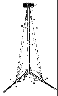
As will be apparent from Figs. 1 and 2, electrical equipment, here a temporary
floodlight
1, and a mast for supporting the floodlight, as described in more detail
herein below, are readily
transportable by a single person in a shoulder bag 2, and need only a simple
manually operable
pump, here a stirrup pump 3, for erection of the mast on site for temporary
support of the
electrical equipment above the ground.
A pneumatically inflatable elongate tube 4, shown before inflation in Fig. 3,
has a first end
coupled to the floodlight, as best shown in Figs. 2 and 5, and a second end 6
coupled to a tripod 7,
which is shown with its legs 8 unfolded in Fig. 3, but before extending the
legs. In this arrangement
the legs are telescopic, comprising a first leg member 9, the proximal end of
which is pivoted at 10
to a tripod centre member 11 which is coupled to the second end 6 of the tube,
and a second leg
member 12 which is telescopically slidable within the first leg member 9 and
clampable thereto
when extended. The distal ends 13 of the first leg members are connected by
struts 14 pivoted to
ends 13 and also to a central member 15. The interlinked struts can be pushed
beyond dead centre
to brace the tripod against unintentional collapse.
A valve 16 is provided for coupling to a pneumatic line 17 connected to pump
3. An
electrically operable pump, for example run from a cigar lighter socket in a
car (automobile) may
be used in place of a manually operable pump. Valve 16 is preferably placed
near to the first end
of tube 4 so that the mast may only be inflated or deflated when lying on the
ground. This avoids
the possible problem of electrical equipment falling on someone as the mast is
deflated.
As can be seen from Figs. 2 and 5, floodlight assembly 1 is mounted on a
bracket 18 so as
to be angularly adjustable, bracket 18 being mounted on a disc 19 closing the
first end 5 of the
5
CA 02833020 2013-11-13
tube. Electrical wiring 20 for the floodlight assembly 1 passes through an air-
tight grommet 21
into the interior of tube 4 and exits at the second end 6 of the tube 4, as
best shown in Fig. 3,
through a similar grommet (not shown).
Elongate flexible members, here in the form of guide lines 22 interconnect the
distal
ends of the first leg members with disc 19 at the first end 5 of the tube.
When the tube 4 is
adequately inflated (Fig. 4), the guide lines 22 are placed under tension.
Guide lines 22 may be
formed from single or multiple ply cords. Additional bracing cooperating with
the guide lines 22
may be provided as shown in Fig. 4. Tube 4 is shown mounting several collars
23 along its
length. Here illustrated only for one such collar, elastic cords 24 are
coupled between the guide
lines 22 and the collar 23. It will be understood that similar elastic cords
may be provided for the
other collars 23.
An alternative intermediate bracing structure cooperating with guide lines 22
is shown
in Fig. 6. In this embodiment, a collar 23 mounts three spokes 25, the distal
end of each spoke
being coupled to a respective guide line 22. The spoke distal ends are also
preferably
interconnected by cords 26.
Fig. 7 shows an alternative embodiment of electrical equipment and supporting
mast,
employing additional bracing structures with spokes 25 as in Fig. 6, but
without the additional
cords 26. As can be seen from Fig. 8, even structure such as that of Fig. 7
will readily collapse for
packing away for transport.
Tripod 7 may be provided with castors 27 so that the erected mast and
equipment may
be wheeled into position. The castors are preferably lockable.
Since the electrical equipment and mast may be packed away in a shoulder bag
for ready
transport, and may be erected on site simply by opening the tripod and
inflating the tube, transport,
erection and taking down can all be performed by a single person without any
tools other than a
simple pneumatic pump, and without any assembly or disassembly of mechanical
parts.
6
CA 02833020 2013-11-13
Other arrangements are feasible. Thus, as illustrated in Figs. 9 to 11, it is
not necessary for
the tube bracing structure to be provided by guide lines. Here respective
flexible webs 28
interconnect mounting points 29 on the legs 8 with both the first 5 and second
6 ends of the tube.
When the tube is inflated and erect on the tripod 7, the respective webs 28
are in tension between
their mounting point 29 and the first end and between the first and second
ends. Flexible cords 30
are here shown interconnecting the mounting points 29. We have found that the
illustrated
structure remains stable even in a moderate wind. To reduce any tendency for
the webs 28 to act
as sails, they may include apertures (not shown) to allow air to pass through
the webs. The webs
may be connected along their inner edges 31 adjacent the tube 4 to collars 23
spaced along the
tube.
While the embodiments illustrated in Figs. 1 to 11 include electrical
equipment in the
form of a floodlight, persons of ordinary skill will readily appreciate that
similar masts may be
employed to mount other forms of equipment that it is desired to temporarily
support above the
ground, such as, without limitation, public address speakers, temporary
traffic signals or
illuminated road signs, security, safety or speed cameras, or communication
equipment such as
satellite dishes, or even equipment that is not electrical, such as, without
limitation, basketball or
netball nets, or signs that do not require illumination. Fig. 12 shows a
netball goal 32 mounted to
a first end of a tube in a structure otherwise as shown in Fig. 9. Fig. 13
shows a public address
loudspeaker 33 mounted by a swivel bracket 34 to a first end of a tube in a
structure otherwise as
shown in Fig. 9. Fig. 14 shows a close circuit television camera 35, for
example a security camera
or a speed camera, coupled by an adjustable mount 36 to a first end of a tube
in a structure
otherwise as shown in Fig. 9. Fig. 15 shows a static warning sign 37 mounted
to a first end of a
tube in a structure otherwise as shown in Fig. 9.
The elongate tube 4 may be formed from a similar material to that described in
our co-
pending British Patent Application No: 0501474.1 (published as GB 2422322 A)
for use in
7
CA 02833020 2014-05-16
providing inflatable sports goals. The material suggested in GB 2422322 for
forming the
tubular struts was natural or synthetic rubber, or plastics substitutes,
preferably reinforced with
nylon thread. Commercial embodiments of sports goals have since been produced
and sold
under our Registered Community Trademark igoan, and are formed with a
thickness in the
material of the struts of around 2mm, and a diameter for the goalposts and
cross-bar of 3 inches
(7.62cm), and work well when inflated with an applied pressure of around 1Bar.
The tubular
members employ inner and outer layers of soft polyvinylchloride (PVC) with
nylon threads
between the two layers helically wound in opposing senses about the axis of
the tube so as to
cross, being laid typically with an angle to the axis of 800 or more. The two
plastics layers are
softened to fuse together in the interstices between the nylon threads. We
have found that this
structure prevents the tube from ballooning (expanding diametrically) in use.
An additional
layer of parallel threads preferably runs along the length of the tubular
member to prevent
stretching lengthwise in use.
Elongate tubes formed in the same way work well with the structures described
in
the present Specification. However, as explained below, and as described and
illustrated in
British published Patent Application GB 2,464,757, we have found that improved
results
can be achieved with alternative tubular structures.
In Fig. 16, tube 4 comprises a layer 38 of plastics, suitably a relatively
soft plastics
material such as PVC, or rubber, overlaid with reinforcing strands 39. The
strands 39
comprise a textile material, preferably nylon. In Fig. 16, the strands 39 are
wound helically
about layer 38 in opposing senses at an angle of 450 to the axis of the
tubular member. The
opposing sense strands may be interwoven, forming a woven textile reinforcing
structure
40.
In Fig. 17, similar reinforcing strands 41 are laid at an angle of 100, again
in
opposing senses, the opposing sense strands being interwoven, thereby
resulting in a woven
textile
8
CA 02833020 2013-11-13
reinforcing structure 42. Our experiments have shown that a tube 4 as
illustrated in Fig. 17 would
be substantially more rigid when inflated to the same operating pressure than
a structure as shown
in Fig. 16, which is already an improvement on the structure described in GB
2422322 and that a
significantly improved rigidity can already be detected at an angle reduced
from the 45 angle of
Fig. 17 to about 300.
Fig. 18 and 19 show a preferred structure with two superposed reinforcing
layers
comprising the woven textile reinforcing structures 40 and 42.
It will be understood that in each of Figs. 16 to 19, the reinforcing
structures are shown
incomplete for the purpose of illustration and explanation, and that in
practice the reinforcing
structures would extend along the entire length of the tube 4.
As best shown in Fig. 19, a second layer 43 of plastics, suitably a relatively
soft plastics
material such as PVC, or rubber overlies the reinforcing structures. As can be
seen from the
drawings, the textile strands are spaced so that, even with two superposed
reinforcing structures, as
in Figs. 18 and 19, there are interstices between the strands. During
application of the second layer
43, or subsequently thereto, the two layers 38 and 42 are warmed sufficiently
to fuse together
through the interstices of the reinforcing layers.
Fig. 20 shows a variation on the structure of Figs. 18 and 19, in which a
further layer
of reinforcing strands 44 is employed, the strands, in this case, extending
parallel to the axis
of the tubular member. These strands help to prevent the tube 4 stretching
lengthwise.
For most purposes contemplated by the present invention, we fmd that a tube 4,
as shown in
Figs. 18 and 19 or in Fig. 20, having a diameter of 3 inches (7.62cm) when
inflated to a typical
inflation pressure of around 1 Bar, namely between 10 and 20 psi (6.89 to
13.79 *104 pascals),
realisable with a foot pump or with an inexpensive tyre pressure pump
operating from the cigar lighter
socket of a vehicle, and an overall thickness of 2mm, works well. The textile
strands are preferably in
the form of thin textile thread. The textile thread may comprise conventional
nylon sewing thread. It
9
CA 02833020 2014-05-16
will be understood, however, that different diameters and thicknesses may be
chosen. The
tube 4 when deflated is readily flexible, allowing the temporary structure to
be packed away
and to be portable.
The adoption of tubes 4, especially as shown in Figs. 18 and 19, which possess
enhanced
rigidity when inflated, raises the prospect of providing masts for equipment
to be mounted aloft as
described above, where the mast is significantly taller than heretofore, or
where the bracing structure is
reduced.