Note : Les descriptions sont présentées dans la langue officielle dans laquelle elles ont été soumises.
CA 02838145 2013-12-24
- 1 -
MANAGING A SUPPLY OF GASEOUS FUEL ON A TENDER
CAR
Field of the Invention
[0001] The present application relates to a technique of managing a supply of
gaseous
fuel on a tender car for a locomotive, and more specifically to managing the
coordination
of various modes of operation of the tender car.
Background of the Invention
[0002] Liquefied natural gas (LNG) is increasingly being considered as
a fuel for
locomotive engines. LNG is a gaseous fuel that is defined herein as any fuel
that is in a
gas state at standard temperature and pressure, which for the purpose of this
disclosure is
defined as 20 degrees Celsius ( C) and 1 atmosphere (atm) respectively. A
gaseous fuel
may also be referred to as a gas in this disclosure. Emissions can be reduced
and the cost
of fuelling lowered when these engines are fuelled with LNG compared to being
fuelled
with diesel.
[0003] In conventionally fuelled locomotives, diesel is stored in tanks
that are located
on the locomotive. A locomotive engine controller controls a fuel pump that
delivers
diesel at predetermined pressures to the engine. In locomotives that fuel with
LNG, the
liquefied gaseous fuel is stored in specially constructed tanks on a tender
car connected
with the locomotive. In applications that require more power than one
locomotive can
provide, or more fuel than one tender car can provide, one or more tender cars
can store
gaseous fuel for one or more locomotives.
[0004] The delivery of gaseous fuel from the tender car to the locomotive
engine is
inherently more complicated compared to delivering diesel fuel, for a variety
of reasons.
There can be delays in delivering gaseous fuel to the locomotive due to start-
up delays for
a cryogenic pump that must be cooled before it can efficiently pump liquefied
gaseous
CA 02838145 2013-12-24
-2-
fuel. Gaseous fuel is delivered from a tender car that is detachable from the
locomotive.
Safety issues must be taken into consideration to ensure that gaseous fuel
does not escape
the fuelling system in the event the tender car separates from the locomotive.
The
distance travelled by the gaseous fuel between where it is stored and where it
is
combusted is considerably greater, which has the potential to further
adversely affect
start-up delays and increases the likelihood of gaseous fuel venting after
shut-down.
Normally, the gaseous fuel is converted from the liquid state to the gas or
supercritical
state before it is introduced to either the intake system or combustion
chambers of the
locomotive engine. Gaseous fuel pressure and temperature are regulated such
that fuel
injection metering can be controlled. This comprises controlling the cryogenic
pump to
maintain the pressure of the fuel within predetermined ranges, and to ensure
the
temperature of the fuel delivered to the engine is above a predetermined
minimum value
such that fuel system components are not damaged and to prevent freezing.
100051 United States Patent No. 5,887,567, issued March 30, 1999 to
White et al.
(hereinafter White), discloses a natural gas fuelling system for cryogenic
fluids between a
container of fuel carried on a flat car and a locomotive. Two configurations
for delivering
LNG from the container to the locomotive are disclosed. In a first
configuration a control
system on a skid frame located on the flat car delivers vaporized gaseous fuel
to the
locomotive. The control system comprises one or more pumps, meters, controls
and
vaporizers. In a second configuration, liquid LNG is supplied to combustion
chambers of
the locomotive engine. Nowhere does White disclose how the control system
functions
over the many operational states of both the locomotive engine and the tender
car.
100061 The state of the art is lacking in techniques for managing a supply of
gaseous
fuel on a tender car during the various operational modes of the tender car.
The present
method and apparatus provides an improved technique for managing supplies of
gaseous
fuel on tender cars.
CA 02838145 2013-12-24
-3-
Summary of the Invention
[0007] An improved apparatus for managing a supply of gaseous fuel on a tender
car
for a locomotive comprises a tender controller configured to interface with a
pumping
and vaporizing apparatus and a communication link for exchanging information
with a
locomotive controller. The tender controller is programmed (1) to receive a
command
signal from the locomotive controller through the communication link
commanding
delivery of gaseous fuel from the tender car to the locomotive; (2) to
transfer at least one
status signal through the communication link to the locomotive controller
indicating
status of the tender car; and (3) with a state machine for managing a
plurality of
operational modes of the tender car. The state machine is responsive to the
command
signal and the at least one status signal to transition between respective
operational
modes. The communication link can comprise at least one of a digital
interface, an analog
interface, a synchronous communication bus and an asynchronous communication
bus.
The communication link is preferably separable from the tender car. The
gaseous fuel can
be at least one of butane, ethane, hydrogen, methane, propane, natural gas and
mixtures
of these fuels.
[0008] In a preferred embodiment, the tender controller is further programmed
to
receive a status signal from the locomotive controller. The status signal is a
locomotive
handshake signal to tender car and the command signal is a gaseous fuel
request signal.
The at least one status signal comprises a tender car to locomotive handshake
signal, a
tender car fault free signal and a tender car ready signal indicating the
tender car is ready
to deliver gaseous fuel.
100091 The state machine comprises a plurality of states representative
of the plurality
of operational modes. The plurality of states comprises at least one of: a
standby state, a
start-up state, a deliver state, a refill state, a disabled state, and a drain
state. The tender
controller can be further programmed to disable delivery of gaseous fuel to
the
locomotive when the state machine is in one of the standby state, the start-up
state, the
CA 02838145 2013-12-24
-4-
refill state, the disabled state and the drain state. The tender controller
can be further
programmed to disable delivery of gaseous fuel to the locomotive when the
locomotive
controller sends a shutdown signal to the tender controller. The tender
controller can be
configured to actuate at least one valve in fill piping and programed to
command the at
least one valve open when the state machine is in the refill state. The tender
controller can
be configured to actuate at least one valve in a drain piping and programed to
command
the at least one valve open when the state machine is in the drain state.
[0010] An improved method of managing a supply of gaseous fuel on a tender car
for
a locomotive comprises receiving a command signal from the locomotive on the
tender
car commanding delivery of gaseous fuel from the tender car to the locomotive;
transmitting at least one status signal from the tender car to the locomotive
indicating
status of the tender car; representing a plurality of operational modes of the
tender car as
a plurality of states; and transitioning between the plurality of states in
response to the
command signal and the at least one status signal.
LOOM In a preferred embodiment the method further comprises receiving a status
signal from the locomotive. The status signal is a locomotive handshake signal
to the
tender car and the command signal is a gaseous fuel request signal. The at
least one status
signal comprises a tender car handshake signal to the locomotive, a tender car
fault free
signal and a tender car ready signal indicating the tender car is ready to
deliver gaseous
fuel.
[0012] The plurality of states comprises at least one of a standby state, a
start-up
state, a deliver state, a refill state, a disabled state, and a drain state.
The method can
further comprise disabling delivery of gaseous fuel to the locomotive when a
current state
of the locomotive is at least one of the standby state, the start-up state,
the refill state, the
disabled state and the drain state. The method can further comprise disabling
delivery of
gaseous fuel to the locomotive when the locomotive sends a shutdown signal to
the
tender car. The method can further comprise commanding at least one valve in
fill piping
CA 02838145 2013-12-24
-5-
open when a current state of the locomotive is the refill state. The method
can further
comprise commanding at least one valve in drain piping open when a current
state of the
locomotive is the drain state.
Brief Description of the Drawings
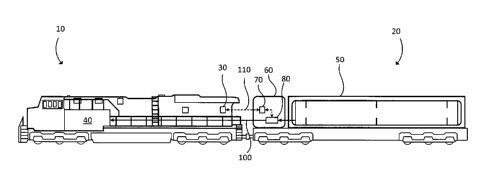
[0013] FIG. 1 is a schematic view of a locomotive and a tender car according
to one
embodiment.
[0014] FIG. 2 is a state diagram view of a control system programmed in a
tender
controller of the tender car of FIG. 2.
Detailed Description of Preferred Embodiment(s)
[0015] Referring to FIG. 1, there is shown locomotive 10 connected with tender
car
20. Locomotive controller 30 controls the operation of engine 40. Gaseous fuel
supply
module 60 controls the delivery of gaseous fuel between cryogenic vessel 50
and engine
40. Pumping and vaporizing apparatus 80 comprises a cryogenic pump (not shown)
and a
vaporizer (not shown) for pressurizing and vaporizing respectively a liquefied
gaseous
fuel stored in cryogenic vessel 50. Exemplary liquefied gaseous fuels are LNG
and
liquefied methane, as wells mixtures of these fuels with other gaseous fuels.
As would be
known to those skilled in the technology there are a variety of other
components in
pumping and vaporizing apparatus 80, which are employed in low pressure
gaseous fuel
systems and/or high pressure gaseous fuel systems. Tender controller 70
controls the
operation of pumping and vaporizing apparatus 80 to take the gaseous fuel from
cryogenic vessel 50 where it is stored in the liquid state and deliver it
through conduit
100 to engine 40 in the gas or supercritical state. Controllers 30 and 70 are
configured to
interface with communication link 110 to exchange information therebetween.
CA 02838145 2013-12-24
-6-
Communication link 110 can comprise at least one of a digital interface, an
analog
interface, a synchronous communication bus and an asynchronous communication
bus. In
a preferred embodiment communication link 110 is a bi-directional
communication link
where locomotive controller 30 sends information to tender controller 70, and
tender
controller 70 sends information to locomotive controller 30. Communication
link 110
comprises a coupling so that it is separable from either controller 30 or 70
in the event
tender car 20 separates from locomotive 10.
[0016] Locomotive controller 30 and tender controller 70 each can comprise
hardware and software components. The hardware components can comprise digital
and/or analog electronic components. In the embodiments herein locomotive
controller
30 and tender controller 70 each comprise a processor and memories, including
one or
more permanent memories, such as FLASH, EEPROM and a hard disk, and a
temporary
memory, such as SRAM and DRAM, for storing and executing a program. As used
herein, the terms algorithm and state machine refer to an application specific
integrated
circuit (ASIC), an electronic circuit, a processor (shared, dedicated, or
group) and
memory that execute one or more software or firmware programs, a combinational
logic
circuit, and/or other suitable components that provide the described
functionality.
[0017] Referring now to FIG. 2, control system 200 for managing a supply of
gaseous
fuel on tender car 20 is shown according to one embodiment. Control system 200
comprises an algorithm in the form of a state machine programmed in tender
controller
70 that is responsive to requests from locomotive controller 30 sent through
communication link 110 and to signals from sensors in and around cryogenic
vessel 50
and pumping and vaporizing apparatus 80 (collectively "the sensors")
representative of a
plurality of operating parameters of tender car 20. States S1, S2, S3, S4, S5
and S6
(collectively S1-6) represent management states for the supply of gaseous fuel
on tender
car 20, which are also referred to as operating modes for tender car 20.
Transitions T 1 ,
T2, T3, T4, T5, T6, T7, T8, T9, T10, T11, T12, T13 and T14 (collectively T1-
14)
CA 02838145 2013-12-24
-7-
represent transitions between respective pairs of states S1-6 that occur when
respective
predetermined criteria are met. Predetermined criteria can be signals received
from
locomotive controller 30, from the sensors, from manual inputs as well as from
other
sources as will be described in more detail below.
[0018] States S1-6 are now discussed in more detail. The definitions of
states S1-6
are summarized in Table 1 below. State S1 is referred to as "Standby" and is
the initial
state when tender controller 70 powers up. In this state no faults have been
detected and
tender controller 70 is waiting for inputs in the form of signals from
locomotive
controller 30, sent over communication link 110, and from the sensors in order
to
transition to other states. State S2 is referred to as "Start-up" and is the
state where
tender controller 70 prepares tender car 20 to be able to deliver gaseous fuel
to
locomotive 10. Components in pumping and vaporizing apparatus 80 can require
time to
bring devices to operating temperature prior to being fully functional. That
is, the
pumping chamber needs to be cooled to cryogenic temperatures and there must be
sufficient heat available in the vaporizer to prevent freezing when the
liquefied gas is
introduced. Accordingly, in state S2, the sensors are monitored for various
operating
parameters such as gaseous fuel level and/or amount, available coolant flow
and ambient
temperature such that the liquefied gaseous fuel can be vaporized and
pressurized to one
or more predetermined target values within a range of tolerance suitable for
delivery to
engine 40. State S3 is referred to as "Deliver" and in this state gaseous fuel
can be
supplied to engine 40 such that gaseous fuel pressure is maintained at the
predetermined
target value within the range of tolerance. State S4 is referred to as
"Refill" and is the
state where cryogenic vessel 50 is to be or is being (re)filled (also known
has 'refueled'
herein) with liquefied gaseous fuel, for example from a refueling facility.
During this
state delivery of gaseous fuel over conduit 100 to engine 40 is suspended. The
level
and/or amount of liquefied gaseous fuel in cryogenic vessel 50 is monitored to
determine
when the refill operation is completed. It is possible that the refueling
facility can detect
when cryogenic vessel 50 is full, for example based on back pressure or fluid
flow rate
CA 02838145 2013-12-24
-8-
through a filling pipe (not shown), and can notify tender controller 70
accordingly.
Alternatively, or additionally, tender controller 70 can monitor the refilling
process
directly by receiving signals from the sensors and can provide feedback to the
refill
operator (for example at the refueling facility). Tender controller 70
commands one or
more valves (not shown) that open passageways through fill piping that allows
cryogenic
vessel 50 to be refilled. State S5 is referred to as "Disabled" and is the
state entered when
tender controller 70 is unable to maintain gaseous fuel pressure at the
predetermined
target value within the range of tolerance, or tender controller 70 cannot
maintain normal
operation of tender car 20, that is the proper functioning of the tender car
in any of the
other states. There are a variety of faults that can cause control system 200
to enter and
remain in state S5. Non-limiting examples of such faults comprise limited or
no gaseous
fuel flow from cryogenic vessel 50 through conduit 110; lack of electrical
power or air
supply; a mechanical, sensor or control system failure; and detection of a
gaseous fuel
leak or thermal event. State S6 is referred to as "Drain" and is the state
where cryogenic
vessel 50 is to be or is being drained of liquefied gaseous fuel. During this
state delivery
of gaseous fuel over conduit 100 to engine 40 is suspended. Tender controller
70 controls
one or more valves (not shown) to allow liquefied gaseous fuel to drain
through drain
piping (not shown) and monitors the level of liquefied gaseous fuel and/or
vapor pressure
in cryogenic vessel 50 to determine when the vessel is empty. In alternative
embodiments
the fill piping and the drain piping can be the same piping, or they can share
a portion of
the same piping. Cryogenic vessel 50 is drained, for example, when tender car
20 is being
serviced. There are a variety of ways cryogenic vessel 50 can be drained.
Preferrably, the
liquefied gaseous fuel is returned to a storage or refueling facility due to
the large
quantity of fuel that can be present in the vessel. Tender controller 70 can
provide the
liquefied gaseous fuel level and/or vapor pressure in cryogenic vessel 50 to
the storage or
refueling facility while the draining operation is proceeding.
CA 02838145 2013-12-24
- 9 -
State Name Short Description
S1 Standby No critical faults detected. Awaiting
notification
from locomotive to request gaseous fuel supply.
S2 Start-up Tender car is preparing to deliver gaseous
fuel to
locomotive.
S3 Deliver Tender car able to deliver gaseous fuel to
locomotive
at one or more predetermined pressures within a
range of tolerance.
S4 Refill Cryogenic vessel is to be refilled or is
refilling.
Gaseous fuel delivery to locomotive is disabled.
S5 Disabled Fault(s) detected, unable to maintain
gaseous fuel
pressure or normal operation.
S6 Drain Cryogenic vessel is to be drained or is
draining.
Gaseous fuel delivery to locomotive is disabled.
Table 1
100191 The predetermined criteria causing transitions T1-14 are now
discussed in
more detail. As mentioned hereinbefore, locomotive controller 30 transmits
command
and status signals over communication link 110 to tender controller 70.
Similarly, tender
controller 70 generates status signals based on signals received from the
sensors on tender
car 20 and transmits specified ones of these status signals to locomotive
controller 30
through communication link 110. These command and status signals from
locomotive
controller 30 and tender controller 70, as well as signals from other sources,
are input into
control system 200 and are made to cause respective transitions T1-14 between
respective
states S1-6. In a preferred embodiment the signals causing transitions T1-14
are tabulated
in Table 2 below. The signals in Table 2 are binary-type signals that can have
true and
false values. In other embodiments other signal types can be employed that
provide
equivalent information to tender controller 70, and a variety of types of
signals can be
employed in control system 200. When the signals in Table 2 have a true value,
this
refers to the signal description being true. For example, when signal SIG1
("Tender
Handshake") is true tender controller 70 is sending a handshake signal to
locomotive
controller 30 indicating that it is connected to communication link 110 and is
ready to
respond to command and status signals from locomotive controller 30, and when
signal
SIG1 is false it is not ready to respond to command and status signals.
Similarly, when
CA 02838145 2013-12-24
- 10 -
signal SIGS ("Locomotive Handshake") is true locomotive controller 30 is
sending a
handshake signal to tender controller 70 indicating that it is connected to
communication
link 110 and is ready to respond to command and status signals from tender
controller 70,
and when signal SIGS is false it is not ready to respond to command and status
signals. In
other embodiments handshake signals SIG1 and SIGS can be alternating-type
signals that
provide respective handshakes to respective controllers 30 and 70 by
continuously
alternating between two or more values. When signal SIG2 ("Gas Request") is
true then
locomotive controller 30 is requesting that gaseous fuel be delivered to
locomotive 10,
and when it is false it is not requesting that gaseous fuel be delivered. When
SIG3 ("Fault
Free") is true then tender car 20 is fault free, and when it is false there is
at least one fault
on the tender car preventing normal functioning. When signal SIG4 ("Ready") is
true
then tender car 20 is ready to deliver gaseous fuel to locomotive 10, and when
it is false it
is not ready. When signal 5IG6 ("Refill") is true then tender car 20 is to be
refueled, and
when it is false it is not to be refueled. Signal SIG6 can be true before and
during
refueling, and after refueling has completed or is to be interrupted signal
SIG6 becomes
or is false. When signal SIG7 ("Drain") is true then tender car 20 is to be
drained or is
draining, and when it is false it is not to be drained. Signal SIG7 can be
true before and
during draining, and after draining has completed or is to be interrupted
signal SIG7
becomes or is false. The "Source" column in Table 2 indicates whether the
signal
originates in locomotive controller 30 or in tender controller 70.
CA 02838145 2013-12-24
- 11 -
Signal Name Short Description Source
SIG1 Tender Tender car handshake signal to Tender
Handshake locomotive controller 70
SIG2 Gas Request Locomotive is requesting delivery of Locomotive
gaseous fuel. Controller 30
SIG3 Fault Free Tender car is fault free and within normal Tender
operating parameters. controller 70
SIG4 Ready Tender car is ready to deliver gaseous Tender
fuel controller 70
SIGS Locomotive Locomotive handshake signal to tender Locomotive
Handshake car. Controller 30
SIG6 Refill Cryogenic vessel refill command for Operator,
tender car, which can be true before and facility
during refueling. controller, the
sensors, switch
SIG7 Drain Cryogenic vessel drain command for Operator,
tender car, which can be true before and facility
during draining. controller, the
sensors, switch
Table 2
100201 Returning to FIG. 2, transitions T1-14 are now discussed in more
detail. The
signals and their values causing transitions T1-14 are summarized in Table 3
below.
Transition T1 refers to control system 200 transitioning from state S1
("Standby") to state
S2 ("Start-up"), which occurs when tender controller 70 receives signal SIG2
("Gas
Request") with a true value. In state S2 tender controller 70 prepares
components in
pumping and vaporizing apparatus 80 for operation. For example, in a preferred
embodiment pumping and vaporizing apparatus 80 comprises a cryogenic pump
external
to vessel 50. Tender controller 70 commands pumping and vaporizing apparatus
80 to
begin cooling the cryogenic pump to reduce vaporization of liquefied gaseous
fuel when
delivered to the cryogenic pump, thereby improving pumping efficiency. Pump
performance and efficiency are reduced when the cryogenic pump is pumping both
liquefied and vaporized gaseous fuel. When the cryogenic pump is internal to
vessel 50
the start-up time of the cryogenic pump can be reduced. In certain
applications there can
CA 02838145 2013-12-24
- 12 -
be other components in pumping and vaporizing apparatus 80 that require a
"warm-up"
period, such as hydraulic pumps and heat sources for the vaporizer.
[0021] Transition T2 refers to control system 200 transitioning from
state S2 ("Start-
up") to state S3 ("Deliver"), which occurs when tender controller 70 detects
that pumping
and vaporizing apparatus 80 is ready to deliver gaseous fuel to locomotive 10
within a
predetermined efficiency. The cryogenic pump and associated piping in
apparatus 80
have been cooled or are cooled such that the likelihood of vaporizing
liquefied gaseous
fuel upstream or within the cryogenic pump is reduced. Other components
requiring a
"start-up" procedure are ready for operation. Tender controller 70 generates
signal SIG4
("Ready") with a true value when gaseous fuel is ready to be delivered.
[0022] Transition T3 refers to control system 200 transitioning from state
S3
("Deliver") to state S1 ("Standby"), which occurs when tender controller 70
receives
signal SIG2 ("Gas Request") with a false value. This can occur when locomotive
controller 30 is requesting a shutdown. When control transitions from state S3
to state Sl,
or from any state where gaseous fuel is present in conduit 100 to state S 1 ,
tender
controller 70 can actuate components (not shown) in gaseous fuel supply module
60 to
capture gaseous fuel in conduit 100 ("shutdown gas") and return it to
cryogenic vessel
50; alternatively, or additionally, the shutdown gas (at least a portion
thereof) can be
directed to an accumulator (not shown) for temporary storage and later
recovery,
introduction into engine 40, or otherwise used, for example to fuel an
auxiliary power
unit. The distance between tender car 20 and locomotive 10 means that there
can be a
relatively large amount of gaseous fuel in conduit 100, which if allowed to
vent to
atmosphere would be wastefully increasing greenhouse gas emissions and
possibly
violate emission regulations in some jurisdictions. By capturing and storing
shutdown
gas, venting to atmosphere is reduced and overall fuel efficiency is
increased.
[0023] Transition T4 refers to control system 200 transitioning from state
S2 ("Start-
up") to state S1 ("Standby"), which occurs when tender controller 70 receives
signal
CA 02838145 2013-12-24
- 13 -
SIG2 ("Gas Request") with a false value. Similar to transition T3, transition
T4 can occur
when locomotive controller 30 is requesting a shutdown. Shutdown gas in
conduit 100
can be captured and stored for later recovery, introduction to engine 40, or
for other uses.
[0024] Transition T5 refers to control system 200 transitioning from
state S1
("Standby") to state S4 ("Refill"), which occurs when tender controller 70
receives a
refueling signal with a true value from the sensors or a switch on tender car
20, or from a
refueling facility (either from a facility controller or an operator's manual
input)
indicating that refueling is to begin. A detection strategy can be employed by
tender
controller 70 to detect the connection of piping between cryogenic vessel 50
and the
refueling facility and the readiness of tender car 20 to receive liquefied
gaseous fuel, such
that tender controller 70 can command the one or more valves in the fill
piping to open.
Normally, engine 40 is not operating while cryogenic vessel 50 is being
refilled.
[0025] Transition T6 refers to control system 200 transitioning from
state S4
("Refill") to state S1 ("Standby"), which occurs when tender controller 70
receives the
refueling signal with a false value before or during the refueling process, or
after the
refueling process has completed. A detection strategy can be employed by
tender
controller 70 to detect the completion of refueling, such that tender
controller 70 can
command the one or more valves in the fill piping to close.
[0026] Transition T7 refers to control system 200 transitioning from
state S5
("Disabled") to state S1 ("Standby"). Tender controller 70 generates signal
SIG3 ("Fault
Free") with a true value, which is subsequently transmitted to locomotive
controller 30,
whenever the current state changes from state S5 ("Disabled") to another
state. This
transition occurs when tender controller 70 determines there are no faults
after the cause
of the fault is removed, or repaired or no longer exists and, if required,
tender controller
70 has received an operator's input acknowledging the fault.
CA 02838145 2013-12-24
- 14 -
[0027] Transition T8 refers to control system 200 transitioning from state
S4
("Refill") to state S5 ("Disabled"). Tender controller 70 generates signal
SIG3 ("Fault
Free") with a false value, which is subsequently transmitted to locomotive
controller 30,
whenever the current state changes from any other state to state S5
("Disabled"). This
occurs when tender controller 70 detects a fault condition. In transition T8,
this can occur
when tender controller 70 determines that refueling can no longer continue,
which can be
due to the variety of faults described in the discussion of state S5 above.
Tender
controller 70 can command the one or more valves in the fill piping to close
when leaving
state S4.
[0028] Transition T9 refers to control system 200 transitioning from
state S3
("Deliver") to state S5 ("Disabled"). This can occur when tender controller 70
detects a
fault condition that can be due to the variety of faults described in the
discussion of state
S5 above. Depending upon the type of fault, tender controller 70 can actuate
the
components in gaseous fuel supply module 60 to return shutdown gases to
cryogenic
vessel 50 or the accumulator. For example, some faults may not require that
engine 40 in
locomotive 10 shutdown, such that gaseous fuel pressure is maintained in
conduit 100
during state S5.
[0029] Transition T10 refers to control system 200 transitioning from
state S2
("Start-up") to state S5 ("Disabled"). This can occur when tender controller
70 detects a
fault condition that can be due to the variety of faults described in the
discussion of state
S5 above.
[0030] Transition T11 refers to control system 200 transitioning from
state S1
("Standby") to state S5 ("Disabled"). This can occur when tender controller 70
detects a
fault condition that can be due to the variety of faults described in the
discussion of state
S5 above.
CA 02838145 2013-12-24
- 15 -
[0031] Transition T12 refers to control system 200 transitioning from state
S1
("Standby") to state S6 ("Drain"), which occurs when tender controller 70
receives a
draining signal with a true value from the sensors or a switch on tender car
20, or from a
refueling/storage facility (either from the facility controller or the
operator's manual
input) indicating that draining is to begin. A detection strategy can be
employed by tender
controller 70 to detect the connection of piping between cryogenic vessel 50
and the
refueling/storage facility and the readiness of tender car 20 to drain and/or
the facility's
readiness to accept liquefied gaseous fuel, such that tender controller 70 can
command
the one or more valves in the drain piping to open. Normally, engine 40 is not
operating
while cryogenic vessel 50 is being drained.
[0032] Transition T13 refers to control system 200 transitioning from state
S6
("Drain") to state S1 ("Standby"), which occurs when tender controller 70
receives the
draining signal with a false value before or during the draining process, or
after the
draining process has completed. A detection strategy can be employed by tender
controller 70 to detect the completion of draining, such that tender
controller 70 can
command the one or more valves in the drain piping to close.
[0033] Transition T14 refers to control system 200 transitioning from
state S6
("Drain") to state S5 ("Disabled"). This can occur when tender controller 70
detects a
fault with the draining operation such that draining can no longer be
supported draining,
which can be caused by an unintentional disconnection of drain piping from
cryogenic
vessel 50, or due to the variety of faults described in the discussion of
state S5 above.
[0034] As would be known to those skilled in the technology, in
alternative
embodiments there can be additional transitions between certain states S1-6
not
illustrated in FIG. 2, but which are implicitly captured in FIG. 2 by
transitioning through
two or more of the illustrated transitions T1-14. The names or naming
convention of the
CA 02838145 2013-12-24
- 16 -
states can vary in alternative embodiments while the purpose and function of
the states
remain substantially the same.
Signal Initiating
Transition From State To State Transition
Signal Value
T1 S1 ("Standby") S2 ("Start-up") SIG2
("Gas Request") True
T2 S2 ("Start-up") S3 ("Deliver") SIG4 ("Ready") True
T3 S3 ("Deliver") S1 ("Standby") SIG2
("Gas Request") False
T4 S2 ("Start-up") S1 ("Standby") SIG2
("Gas Request") False
T5 S1 ("Standby") S4 ("Refill") SIG6 ("Refill") True
T6 S4 ("Refill") S1 ("Standby") SIG6
("Refill") False
T7 S5 ("Disabled") S1 ("Standby") SIG3 ("Fault Free") True
T8 S4 ("Refill") S5 ("Disabled") SIG3 ("Fault Free") False
T9 S3 ("Deliver") S5 ("Disabled") SIG3 ("Fault Free") False
T10 S2 ("Start-up") S5 ("Disabled") SIG3 ("Fault Free") False
T11 S1 ("Standby") S5 ("Disabled") SIG3 ("Fault Free") False
T12 S1 ("Standby") S6 ("Drain") SIG7 ("Drain") True
T13 S6 ("Drain") S1 ("Standby") SIG7 ("Drain") False
T14 S6 ("Drain") S5 ("Disabled") SIG3 ("Fault Free") False
Table 3
[0035] Control system 200 manages the supply of gaseous fuel on tender car 20
by
coordinating the various operational modes of the tender car to increase safe
and efficient
operation of components for delivering, refuelling, draining, capturing and
storing
gaseous fuel. Gaseous fuel is delivered to locomotive 10 in an efficient, safe
and timely
manner. When cryogenic vessel 50 is being refilled or drained, control system
200
improves the safe handling of gaseous fuel on tender car 20 and safe operation
of
components that deliver or fuel with gaseous fuel. In the event of faults
control system
200 can determine whether to capture and store gaseous fuel in delivery pipes
between
tender car 20 and locomotive 10 (conduit 100) to reduce the likelihood of
venting to
atmosphere, and such captured and stored gaseous fuel can be later introduced
into
engine 40.
[0036] While particular elements, embodiments and applications of the present
invention have been shown and described, it will be understood, that the
invention is not
CA 02838145 2013-12-24
- 17 -
limited thereto since modifications can be made by those skilled in the art
without
departing from the scope of the present disclosure, particularly in light of
the foregoing
teachings.