Note : Les descriptions sont présentées dans la langue officielle dans laquelle elles ont été soumises.
CA 02840661 2013-12-27
WO 2013/005011
PCT/GB2012/051530
1
Level Measurement Method and Apparatus
The present invention concerns a method for the measurement of a level of
contents within a
container or vessel and an apparatus which is adapted to be useful in carrying
out the inventive
method. In particular the method is a method of measuring a level, especially
of a fluid, within a
container by measurement of radiation emitted by a source of radiation and
detected by a
radiation detector after it has passed through a portion of the container in
which the contents
may be present.
The measurement of a level in a container by means of radiation has been well
known and
widely applied for many years. For example US-A-3654458 describes the
detection and control
of a liquid level in a sub-sea vessel using a source of ionising radiation and
a plurality of
detectors.
There is a need for improved level measurement systems which provide
advantages over the
apparatus and methods of the prior art.
According to the invention we provide a method of determining the location
within a
.. measurement range of a boundary between two phases within a vessel, each
phase having
different radiation attenuation characteristics, comprising the steps of:
(a) providing at least one source of radiation capable of emitting radiation
through a portion of
the interior of the vessel
(b) providing a plurality of radiation detectors, each detector being capable
of detecting, within a
part of said measurement range, radiation emitted by the source,
(c) providing a data processing means for calculation of the position of the
phase boundary
from the amount of radiation detected by the detectors;
characterised in that the data processing means calculates the position of the
phase boundary
from the amount of radiation detected by the detectors by
(i) determining within which detector stage the phase boundary is located
and then
(ii) determining the position of the phase boundary within the detector stage
determined in (i)
The method accurately determines phase boundary position when deposits build
up on the
vessel walls, when the pressure changes or when foam develops in the vapour
space above a
liquid. The method also offers improved accuracy over conventional level or
interface
measurement systems of the prior art even when no foam or deposits are
present.
According to a further aspect of the invention we provide an apparatus for
measuring the
position within a measurement range of a boundary between two phases within a
vessel, each
phase having different radiation attenuation characteristics, comprising the
steps of:
2
(a) providing at least one source of radiation capable of emitting
radiation through a
portion of the interior of the vessel
(b) providing a plurality of radiation detectors, each detector being
capable of detecting,
within a part of said measurement range, radiation emitted by the source,
.. (c) providing a data processing means for calculation of the position of
the phase boundary
from the amount of radiation detected by the detectors;
characterised in that the data processing means calculates the position of the
phase
boundary from the amount of radiation detected by the detectors by
(i) determining within which detector stage the phase boundary is
located and then
(ii) determining the position of the phase boundary within the detector
stage determined
in (i).
According to a further aspect of the invention we provide a method of
determining the location
within a measurement range of a boundary between two material phases within a
vessel,
each phase having different radiation attenuation characteristics, comprising
the steps of:
.. a) providing at least one source of radiation capable of emitting radiation
through a portion of
the interior of the vessel
b) providing a plurality of radiation detectors, each detector being capable
of detecting,
within a part of said measurement range, radiation emitted by the source,
c) providing a data processing means for calculation of the position of the
phase boundary
from the amount of radiation detected by the detectors, the data processing
means being
capable of comparing the count-rate produced by each detector measured during
operation of the method with the count-rate produced by the same detector when
it is just-
covered with the more-dense phase and when it is uncovered;
wherein the data processing means calculates the position of the phase
boundary from the
amount of radiation detected by the detectors by
(i) in a first step, determining within which detector stage the phase
boundary is located
and then
(ii) in a second step, determining the position of the phase boundary within
the detector
stage determined in (i).
CA 2840661 2019-04-08
2a
According to a further aspect of the invention we provide an apparatus for
measuring the
location within a measurement range of a boundary between two phases within a
vessel,
each phase having different radiation attenuation characteristics, comprising:
at least one source of radiation capable of emitting radiation through a
portion of the interior
of the vessel, a plurality of radiation detectors, each detector being capable
of detecting,
within a part of said measurement range, radiation emitted by the source, a
data processing
means for calculation of the position of the phase boundary from the amount of
radiation
detected by the detectors, the data processing means being capable of
comparing the count-
rate produced by each detector measured during operation of the method with
the count-rate
produced by the same detector when it is just-covered with the more-dense
phase and when
it is uncovered;
wherein the data processing means is programmed to calculate the position of
the phase
boundary from the amount of radiation detected by the detectors by
(i) in a first step, determining within which detector stage the phase
boundary is located and
then (ii) in a second step, determining the position of the phase boundary
within the detector
stage determined in (i).
The radiation-attenuation characteristics of the phases present in the vessel
between which
the boundary is desired to be located are different. This means that the
radiation from the
source transmitted to a detector through one of the phases is less than the
radiation from the
source transmitted to a detector the same distance through the other one of
the phases. In
this way the amount of material of each phase between the source and the (or
each) detector
affects the transmission of radiation through the bulk material. A comparison
of the detected
transmitted radiation therefore allows changes in the density of the medium to
be measured
so that the phase boundary may be located.
In a conventional level measurement system of the prior art, a radiation
source is arranged to
emit radiation through the interior of a vessel towards one or more detectors
arranged along a
path forming the measurement range of the level measurement system. When, for
example,
the vessel contains a liquid and a headspace gas, one or more of the detectors
may be below
the level of the liquid and one or more detectors may be located above the
level of the liquid,
i.e. within the headspace. In many prior art systems, a single, elongate
detector in the form of
a length of scintillating material is used, such that part of the scintillator
is above the liquid
level and part below. Radiation is attenuated by the medium through which it
travels so that
CA 2840661 2019-04-08
2b
less than 100% of the radiation emitted by the source is detected by the
detectors. The
amount of radiation emitted by the source which is detected by a detector
after transmission
through a medium is proportional to the density and the amount of the medium
through which
it has travelled. The level of a liquid within a vessel, for example, is
therefore conventionally
.. measured by determining the total amount of radiation emitted by the source
and detected by
the detectors and identifying a change in the total detected radiation as the
level of liquid
changes. A relatively low liquid level provides overall a less dense medium
for transmission of
radiation and therefore relatively more radiation is detected than when the
liquid level is
higher. In conventional level measurement instruments of the prior art, the
total integrated
.. count rate from the complete detector system is used to calculate level.
Any reduction in
count rate, caused for
CA 28406612019-04-08
CA 02840661 2013-12-27
WO 2013/005011
PCT/GB2012/051530
3
example by the deposition of solids on the vessel walls, pressure changes or
the development of
foam in the vapour space, will lead to an erroneously high level measurement.
One advantage of
the method and apparatus described herein is that it allows accurate level
measurement despite
the build-up of deposits or the development of foam in the vapour space. A
second advantage
of the invention is that it allows improved measurement accuracy even when no
foam or
deposits are present. This second advantage arises because measurement errors
caused by the
effect of natural, statistically predictable fluctuations in count rate are
reduced when compared
with those produced by conventional prior art systems.
The measurement range is the extent of the vessel within which the phase
boundary can be
detected by the method and apparatus. The apparatus is normally designed to
have a
measurement range covering the expected variation in the location of the phase
boundary.
Often this covers most or all of the practical height of the vessel although
in some applications
the measurement range may be designed to be smaller when the phase boundary of
fill of the
vessel is not expected to vary by much. The part of the measurement range over
which each
detector is capable of detecting radiation will be referred to as the detector
stage. Taken
together, the detector stages cover the entire measurement range. The detector
stages of
adjacent detectors are preferably arranged to be contiguous. The measurement
range normally
extends along a part of the vessel covering the height over which the level is
expected to vary.
The detectors may be immersed in the vessel contents directly but are
preferably located
outside the vessel or within a protective housing, chamber or dip-tube
positioned within the
vessel. When the detectors are located outside the vessel, they are usually
adjacent to or
mounted on the vessel wall. The detectors are oriented so that they detect
radiation from the
source. The detectors may be shielded from radiation arriving from a direction
other than the
direction of the source.
The method and apparatus of the invention is particularly suitable for
determining the location in
a vessel of a phase boundary between two fluid phases although its application
to vessels
containing solid phases is not excluded. A widespread application for such
apparatus is the
determination of a liquid level in a vessel containing a liquid and a gas
phase (which may be e.g.
air, a vacuum or a headspace vapour). The phase boundary determined by the
method of the
invention is then the liquid level. The vessel may alternatively contain more
than one liquid
phase, e.g. an aqueous and an organic phase, such as oil and water.
In a preferred form the radiation comprises ionising radiation such as X-rays
or, more preferably,
gamma rays. Alternatively microwaves, radio waves, or sound waves may be used.
The
radiation used is selected by the transparency to the radiation of the vessel
and/or its contents
(i.e. the attenuation coefficient of the medium) and the availability of
suitable sources and
detectors. Radiation from the visible or near-visible spectrum may be used but
its use would be
CA 02840661 2013-12-27
WO 2013/005011
PCT/GB2012/051530
4
very limited. For scanning large solid structures such as process vessels,
gamma radiation is
greatly preferred. Suitable sources of gamma include 6 Co and 137cs, 133Ba,
241Am, 24Na and
182Ta, however any gamma-emitting isotope of sufficient penetrating power
could be used, and
many such are already routinely used in level measurement devices. For a
permanent
installation, a radioisotope source should be chosen to have a relatively long
half life to give the
equipment a satisfactory service life. Usually, the half-life of the
radioisotope used will be at
least 2, and desirably at least 10, years. The half-lives of the radioisotopes
mentioned above
are: 137Cs gamma ca. 30 years, 133Ba ca. 10 years and 241Ann ca. 430 years.
Suitable sources
generally emit radiation at energies between about 40 and 1500 keV and
suitable detectors can
detect such radiation with sufficient sensitivity that the radiation detected
varies according to the
density of the transmission medium.
One or more than one sources may be used in the level measurement method and
apparatus.
Normally the number of sources used is not more than 10 and is preferably from
1 ¨ 4. Each
source may emit a beam of radiation towards more than one detector, generally
from 4 ¨ 10
detectors, but from 2 ¨40 detectors may be used, depending on the size /
detection area of
each detector and the resolution required of the apparatus.
The particular detectors used in the apparatus and method are not in
themselves critical
although in practice compact devices will usually be chosen. The detectors may
be electrically
powered e.g. Geiger-Muller (GM) tubes or scintillation detectors linked with
photo-detectors such
as photonnultipliers or photodiodes, or un-powered as in simple scintillation
devices. Among
electrically powered detectors, GM tubes are preferred, because they are
electrically and
thermally robust and are available in mechanically robust forms. Among un-
powered detectors
scintillation detectors linked to counters by fibre optic links (optionally
with a light detector such
as a photonnultiplier or photodiode outside the container for the medium under
test) are
particularly useful. When electrically powered detectors are used and
especially when the
apparatus is used in a combustion or explosion risk environment, it is
desirable that the total
electrical energy and power associated with the detectors is sufficiently low
as not to be a
significant source of ignition in the event of system failure (particularly
resulting in direct contact
between combustible or explosive materials and any electrically live
components).
The counting devices for any of these detectors will usually be electronic and
each detector will
be associated with a counter which will usually be linked to the data
processor. It will usually be
practical to provide a counter for each detector, but time division
multiplexing of counters can be
used although with a resultant increase in the time needed for calculation and
consequently an
increase in the minimum time interval between measurements.
CA 02840661 2013-12-27
WO 2013/005011
PCT/GB2012/051530
The data processor may be any commercial processor which is capable of
operating on the data
from the counters to produce the required information. The processor may
comprise a standard
computer or may be a dedicated device which is installed as a part of the
boundary location
system. The processor is linked to the counters so that the count data may be
passed to the
5 processor. The link may be wired or wireless, depending on the
circumstances and
requirements of the system. The processor is capable of interrogating the
counters at pre-
determined intervals of time and for a pre-determined duration and therefore
includes a timing
device. The processor calculates the count-rate produced by each detector and
smoothes the
count-rate values according to a time constant Tc or another filtering
algorithm. Tc is a
calibration parameter that is often used in nucleonic applications. Suitable
smoothing algorithms
are well-known in the art of instrument design. If a steady count-rate should
suddenly change by
AQ then, after time t has elapsed, the measured change in count-rate will be
t
AQ (t) = AQ 1¨e . For a fixed radiation intensity, a detector will
produce a smoothed
count-rate Q that fluctuates by an amount (+/- one standard deviation).
V2QT,
The processor may also correct the smoothed count-rate values for the effects
of source decay
according to the half-life of the isotope used in the application.
The processor is also linked to an interface such as a display, a control
system or an alarm by
which information concerning the phase boundary location may be used to
control the vessel
process parameters if required. Suitable data processing apparatus are widely
available and
already known and used in conventional level measurement systems. The skilled
person may
readily select an appropriate device. The selection of the data processing
apparatus does not
form a part of the present invention although the operation of the apparatus
does.
The data processing means is adapted to calculate the position of the phase
boundary from the
amount of radiation detected by the detectors in a two-step method, in which,
in a first step, it is
determined in which detector stage the phase boundary is located, and then, in
a second step,
the position of the phase boundary within the relevant detector stage is
calculated.
The first step is preferably done by comparing the count-rate from each
detector at the time of
measurement with the count-rate detected by the same detector when it is just-
covered, i.e.
when the detector stage is just full of the more dense phase and when it is
uncovered, i.e. when
the detector stage is empty of the more dense phase and/or full of the less-
dense phase. If the
count-rate from a particular detector stage is significantly greater than the
count-rate measured
CA 02840661 2013-12-27
WO 2013/005011
PCT/GB2012/051530
6
when the same detector is just-covered, then that detector stage is very
likely to contain some of
the less-dense phase and a phase boundary is likely to be present in that
detector stage. In
such a case, all detector stages above that detector stage should also contain
one or more less-
dense phases. Therefore it is preferred to confirm the detector stage
containing the phase
boundary by comparing the count-rate from the adjacent higher detector stage
with its own just-
covered count-rate. In a particularly preferred method, the detector stage in
which the phase
boundary is located is determined by the data processor carrying out the
following method:
a) for each detector n, where n varies from 1 to N and N is the number of
detectors, acquire the
current smoothed and decay-corrected count-rate Q,
b) Calculate:
Q nfXQn for all n stages
where Qnf is the count-rate when the dense phase is just covering the nth
stage, and T, is the
time constant. X is a number ranging from 0 to 5 that is chosen depending on
the accuracy and
response time of the system. X is preferably 0, but may be larger than zero in
applications
where system stability is critical.
c) Starting with lowest stage (n = 1), establish whether:
Qnf + IXQ
v T. (Algorithm A)
d) If algorithm A is not satisfied, increment for n until the lowest stage
p is reached where
algorithm A is satisfied i.e.:
XQ
___________ Q > 0 +
P Pf II2Q T
p c
Stage p is the lowest stage in the detector for which algorithm A is
satisfied. We say that the
phase boundary is contained in detector stage p. If algorithm A is not
satisfied for all n from 1 to
QX ,
N-1 and the relationship Qõ Aif _________________________________ is also
not satisfied, then the phase boundary is
V2QNTc
assumed to be above detector stage N.
In an alternative method, which provides additional robustness, the following
procedure can be
followed:
a) for each detector n, where n varies from 1 to N and N is the number of
detectors, acquire the
current smoothed and decay-corrected count rate Qn
b) Calculate:
CA 02840661 2013-12-27
WO 2013/005011
PCT/GB2012/051530
7
Q IXQn for all n stages
.v2aTe
where Qr,f, Tc , X are as given above.
c) Starting with lowest stage (n = 1), establish whether:
XQ XQ(n+1)
Q >Q + and Q(n-4) Q(n+1) f ____________________ (Algorithm B)
V2Q,T. 112Q0,4)17,
d) If algorithm B is not satisfied, increment for n until the lowest stage
p is reached where
algorithm B is satisfied i.e.:
XQ XQ(pii)
Q >Q + If2Q
____________________________________________ and Q(p+1) > ¨ =,=-= 0 ( p+1) f +
P Pf T
P c V2Q(p+07',
Stage p is the lowest stage in the detector for which algorithm B is
satisfied. We say that the
phase boundary is contained in detector stage p. If algorithm B is not
satisfied for all n from 1 to
N 10 N-1 and the relationship QN QAT/ i
XQ
s also not satisfied, then the phase boundary is
V2QNT.
assumed to be above detector stage N.
It is preferred that the detectors are arranged so that stage N is at the top
of the vessel and that
the highest phase boundary position falls within detector stage N. Using this
preferred
arrangement, algorithm B is incremented for n until n = (N -1). If algorithm B
has not been
satisfied then the count-rates from stages (N-1) and N are examined. If the
vessel is full then
algorithm B is not satisfied so the phase boundary position is above stage (N -
1). The data
processor is programmed to assume that the liquid level is in stage N when n
is incremented
from (N -1) to N. If the vessel is full, the second step, described below,
will confirm that the level
= 100%.
.. In the second step, the position of the phase boundary within the detector
stage found to contain
the phase boundary is calculated. This is preferably done by calculating the
ratio of count rate
detected by the detector to the count rate when the detector stage is just
covered. In a preferred
method, the position of the phase boundary within the detector stage p found
to contain the
phase boundary is determined by the data processor by solving Algorithm C.
V vp
h ___ pe * length of detector stage p (Algorithm C)
\QPc Q.Pf
where:
h is the height of the phase boundary above the bottom of detector stage p,
Ope is the count-rate when the dense phase is below detector stage p.
Q, is the current smoothed and decay-corrected count-rate in detector stage p.
CA 02840661 2013-12-27
WO 2013/005011
PCT/GB2012/051530
8
Qpf is the count-rate when the dense phase is just covering detector stage p.
In order to determine the level within the measurement range of the phase
boundary, the length
of the measurement range below detector stage p is added to the result of
Algorithm C to give a
total height of the phase boundary above the bottom of the measurement range.
When all of the
detector stages are the same length and the detectors are arranged linearly:
rQ Q P
The level of the phase boundary = stage length (p-1)+
QpeQpry
Q
100 r (Q Q P
u9 and % level = ¨ ¨1)+ Pe
Q ¨Q
\ Pe Pf
where N = total number of detector stages.
When detector stages are not the same length, or not arranged linearly, for
example on a drum
vessel, then the equations need to be modified appropriately. Additional
modifications to these
equations are necessary if the detector is not situated directly in contact
with the vessel wall, as
shown in Figure 2. In this case, due to geometric considerations of the
radiation paths, the level
in the vessel is slightly different to the level on the detector. All of these
modifications are simple
changes and would be clear to somebody skilled in these matters.
In order to further improve accuracy, an alternative method for determining
the position of the
phase boundary within a stage is to calibrate the count rate as a function of
level within each
stage. This can be done either experimentally, or by modelling.
One, Qnf are obtained in a calibration step. One is measured for each detector
n when the vessel
is empty or contains only the less dense phase. Qnf is measured for each
detector stage when
the vessel has been filled with the dense phase to a level where the dense
phase just covers the
detector, or just fills the detector stage. Alternatively, 0 0 may be obtained
by calculation
One, ¨nf
using an appropriate model from the path length between the source and the
detector, the
energy of the source radiation, the density of the dense and less dense phases
and the mass
absorption coefficient of the material. When the instrument is calibrated, the
count rates over a
prolonged period, should be measured to provide time-averaged count rates to
determine One
and Qnf which are as representative a figure as possible.
In some applications, the nature of the contents of the vessel causes
deposition of solid or thick
liquid material on the walls of the vessel leading to a reduction in the
radiation detected by the
detectors opposite the deposits. Ideally the deposits are cleared away from
the vessel walls but
it is often necessary to operate a level detector in the presence of these
deposits, the thickness
of which may be unknown. Accordingly, a preferred method further comprises a
third step in
CA 02840661 2013-12-27
WO 2013/005011
PCT/GB2012/051530
9
which the effect of the deposition of a dense phase, such as solids or a thick
liquid, on the wall of
the vessel may be accounted for in the calculation of the position of the
phase boundary. The
third step comprises resetting the empty counts calibration One to the
currently measured counts
Qn for all detector stages above stage p, the level of the calculated detector
stage containing the
phase boundary. The difference between On, measured during normal operation of
the method,
and the initial value One, measured when the vessel was empty, may also be
used to calculate
an approximate density of deposits that are present on the vessel wall. When
the nature of the
deposits is known, the thickness of these deposits may be approximately
calculated. When the
reduction in radiation above the phase boundary has reached a value which is
likely to affect the
measurement method, the vessel may be cleared of deposits. This third step may
be useful
when the deposits that build up on the vessel wall have a density when wet
which is greater than
the density of the more dense of the phases forming the phase boundary.
The invention is further described in the accompanying drawings which are:-
Fig 1: a section through a vessel incorporating a level measurement system
according to the
invention; and
Fig 2: a section through a vessel incorporating an alternative embodiment of a
level
measurement system according to the invention.
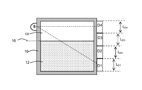
In the level measurement system shown schematically in Fig 1, a radiation
source "S" is
arranged to emit radiation through the interior of a vessel 10 towards 4 x
200nnnn long Geiger
tubes D1, D2, D3, & D4 arranged linearly to produce a detector 800nnnn long
arranged
approximately vertically down an opposed wall of the vessel. The vessel
contains a liquid 12
and a gas 14. D1 and 02 are below the level of the liquid and D4 is above the
level of the liquid.
The system has been calibrated so that the count rate on each detector Dn when
above the
level of the liquid One and when just covered by the liquid Onf are known.
XQ
For detectors D1 and D2, Q1 f + and Q2 Q, f + ,XQ2 are not satisfied.
Therefore the phase boundary between liquid 12 and gas 14, i.e. the level 16
of the liquid 12, is
calculated to be above 02. The lowest detector stage for which algorithm B is
satisfied is 03.
Therefore the level of liquid 12 is determined to be within detector stage 3.
(
The level of liquid 12 therefore = L Dl L D2 + LD3 Q3e ¨
,.ge Q3,1
where L Dr = length of detector stage n.
CA 02840661 2013-12-27
WO 2013/005011
PCT/GB2012/051530
When the method described above is utilised to determine the position of the
phase boundary,
the measurement is unaffected by the build-up of solid deposits on the vessel
walls or by the
presence of foam above a liquid level. Even when no deposits and no foam are
present, the
5 method provides enhanced accuracy over conventional instruments of the
prior art. For
example, assume that there are N detector stages each with length LD. For
simplicity, assume
that each stage produces a count-rate Qne when uncovered and zero count-rate
when covered
by the liquid.
According to the method described herein, it is determined that the level is
contained within a
10 particular stage and the position of the phase boundary within the
detector stage is then
calculated. The maximum stage count-rate is Qne (corresponding to minimum
level in the stage)
and the minimum stage count-rate is zero (corresponding to maximum level in
the stage). So,
the stage count-rate changes by One as the level changes by LD
Qne
The uncertainty in the maximum stage count-rate is + , (one standard
deviation).
V2QõeT,
Since the stage count-rate changes by One as the level changes by LD, an
uncertainty in count-
ratene of , leads to a maximum uncertainty in phase boundary position of
112QõT,
Qne LD
V2QneT, Qõ
LD
ie + , (1)
112QõT,
Note that this is the maximum error when the level is in any stage.
For comparison, in prior art systems the total integrated count-rate from the
complete detector
system is used to calculate level. In such a prior art case, when the level is
close to the bottom
of the measurement range the total detector count-rate is NQn0 and the
uncertainty associated
NQõ,
with this count-rate is , .The total count-rate changes by NOne as the
level changes
112NQT,
NQre
by NLD (ie over the measurement range). So, an uncertainty in total count-rate
of j2NQT
NQõ NL
leads to an uncertainty in level measurement = + ,
V2NQõ,T, NQõ,
CA 02840661 2013-12-27
WO 2013/005011 PCT/GB2012/051530
11
L VTV
ie + ________________ (2)
V2QõT,
A comparison of (1) and (2) indicates that for low levels, level measurement
according to the
invention is more accurate (by a factor VITT ) than measurements provided by
prior art systems
that utilise the total integrated count-rate from the entire detector system.
The improvement in
accuracy becomes smaller as the level rises, but for all levels up to the top
of the range,
measurements made according to the method of the invention are more accurate
than
measurements provided by said prior art systems.