Note : Les descriptions sont présentées dans la langue officielle dans laquelle elles ont été soumises.
CA 02841403 2014-01-09
WO 2013/008035
PCT/GB2012/051682
1
1 Method of acoustic surveying
2
3 The present invention relates to distributed optical fibre sensors for
distributed acoustic
4 sensing, methods of use in acoustic surveying and applications thereof.
In particular,
modal analysis of distributed acoustic data obtained in-well provides a means
for
6 monitoring well integrity.
7
8 Background to the invention
9
Flow metering is a key measurement when attempting to optimise production from
a well.
11 However, current technologies are limited to flow measurements at a
limited number of
12 discrete locations, for example by permanent installation of optical
flow meters at a
13 number of spaced locations along a length of production tubing.
14
Well integrity is also a key concern. However, using such a flow metering
system again
16 only allows measurements to be made at discrete points ¨ although by
measuring the
17 speed of sound in the tubing the contents of the tubing can be
determined, albeit only at
18 those discrete points.
19
CA 02841403 2014-01-09
WO 2013/008035 PCT/GB2012/051682
2
1 Noise logging can also be employed to determine in-well fluid flow and
composition.
2 Again, such measurements can only be made at discrete points, unless they
are made
3 while lowering a hydrophone into the well. Such a measurement requires an
intervention,
4 and so is generally undesirable.
6 Downhole optical fibres are used in a number of different applications as
a replacement for
7 conventional technologies that cannot withstand the pressures and
temperatures that fibre
8 based sensors can withstand. Furthermore, distributed optical fibre
sensors may allow
9 simultaneous measurements at a significantly greater number of
measurement points ¨
not limited by individual physical sensors.
11
12 It is proposed by the Applicant to employ optical fibre based sensors,
such as their
13 proprietary Intelligent Distributed Acoustic Sensor (iDAS), for the
purposes of wellbore
14 surveying and in particular downhole flow metering to obtain a
distributed measurement of
in-well fluid flow. However, it is not obvious how the skilled person could
employ the iDAS
16 technology to produce meaningful survey data or useful distributed flow
data.
17
18 It is anticipated that the solution will be applicable to many different
applications and to
19 data obtained from a variety of different measurements (i.e. not just
iDAS).
21 It is therefore an object of at least one embodiment of the present
invention to provide a
22 method of surveying a wellbore based on obtaining a distributed acoustic
measurement of
23 the wellbore.
24
It is also an object of at least one embodiment of the present invention to
provide
26 corresponding methods of monitoring a formation and of monitoring fluid
flow within a
27 wellbore.
CA 02841403 2014-01-09
WO 2013/008035 PCT/GB2012/051682
3
1 Summary of the invention
2
3 According to a first aspect of the invention, there is provided a method
of surveying a
4 wellbore comprising: obtaining a distributed acoustic measurement within
and
corresponding to at least a portion of the wellbore; processing the
distributed acoustic
6 signal to obtain a distributed speed of sound measurement within the
wellbore; and
7 analysing variations in the distributed speed of sound measurement to
derive information
8 relating to a formation and/or fluid in the wellbore; the method further
comprising
9 determining an acoustic mode corresponding to the, each, or a distributed
speed of sound
measurement within the wellbore.
11
12 A measured acoustic signal is likely to comprise contributions from
several spatially
13 simultaneous acoustic modes within the wellbore, each having a
corresponding speed of
14 sound. The present invention makes use of a distributed speed of sound
measurement
(i.e. speed of sound determined as a function of position) and, by looking at
absolute
16 values of and changes in the speeds of sound as measured, derive
information about a
17 formation and/or fluid within the wellbore.
18
19 Preferably, the analysis comprises analysing variations in the
distributed speed of sound
measurement as a function of position. Additionally, or alternatively, the
analysis
21 comprises analysing variations in the distributed speed of sound
measurement as a
22 function of time.
23
24 Analysing variations as a function of position allows, for example, the
location of defects or
changes to be determined. Analysing variations as a function of time allows,
for example,
26 real time monitoring of the occurrence and developments of defects or
changes. A
27 combination of both position- and time-based analysis provides a means
to monitor where
28 and when defects or developments occur, and track them.
29
Preferably, processing the distributed acoustic signal comprises determining a
plurality of
31 distributed speed of sound measurements within the wellbore as a
function of position.
32
33 By way of example, an installation comprising a cased wellbore and a
recovery pipeline
34 disposed therethrough will result in the presence of at least three
acoustic modes (as
described in the following description of the figures). Determining speed of
sound for a
36 particular acoustic mode (whose position is known) provides a mechanism
for tracking the
CA 02841403 2014-01-09
WO 2013/008035 PCT/GB2012/051682
4
1 behaviour of that acoustic mode by virtue of the distributed nature of
the speed of sound
2 measurement.
3
4 It is therefore preferable that processing the distributed acoustic
signal comprises
obtaining a plurality of distributed speed of sound measurements.
6
7 Preferably, the analysis comprises determining an acoustic amplitude
corresponding to
8 the, each or a distributed speed of sound measurement. Alternatively, or
additionally, the
9 analysis comprises determining relative amplitudes corresponding to
different acoustic
modes. Alternatively, or additionally, the analysis comprises determining
dispersion
11 characteristics of the, each, or an acoustic mode. Alternatively, or
additionally, the
12 analysis comprises determining an upper-frequency cut-off for the
presence of modal
13 phenomena.
14
Most preferably, the analysis comprises inverting a wellbore model against the
distributed
16 speed of sound measurement in order to determine a value of one or more
unknown
17 parameters in the wellbore model. Optionally, the wellbore model is
configured to receive
18 as an input one or more speed of sound measurements and output one or
more
19 corresponding wellbore parameters.
21 As described in more detail below, acoustic propagation within a
wellbore can be modelled
22 using (for example) full 3-D elastodynamic equations and parameters of
the well. Such
23 parameters might include the hardness of the formation. Such a wellbore
model can
24 therefore be modified to treat speed of sound as a known parameter and
other model
parameters as unknowns.
26
27 Preferably, the analysis comprises identifying one or more features in
the, each or a
28 distributed speed of sound measurement and attributing the one or more
features to one
29 or more corresponding events.
31 Features in, say, a trace of speed of sound versus position for a
particular acoustic mode
32 may reveal the presence (and, of course, location) of a gas bubble or a
hydrate clump, a
33 change in pipe diameter, a leak in the casing or some undesirable
downhole activity.
34 These features may be identified by manual inspection, neural network
processing, pattern
recognition or, in light of the teachings of the present application, one of a
variety of
CA 02841403 2014-01-09
WO 2013/008035 PCT/GB2012/051682
1 suitable feature identification methods that will be apparent to the
skilled person. In
2 addition, if multiple acoustic modes are present, identification of which
modes exhibit the
3 features, relative strengths therebetween, etc. all provide diagnostic
information regarding
4 the wellbore and/or the formation.
5
6 Optionally, identifying one or more features comprises determining the
presence and/or
7 location of one or more discontinuities; variations; and/or relative
variations between
8 modes, in relation to speed of sound and/or amplitude corresponding to an
acoustic signal.
9
Optionally, the analysis comprises averaging the, each, or a distributed speed
of sound
11 measurement along at least a portion of the wellbore.
12
13 This provides an indication of peak quality and, in the presence of
multiple acoustic
14 modes, a comparative measure of signal strengths and profiles.
16 According to a second aspect of the invention, there is provided a
method of monitoring a
17 formation, comprising the method of the first aspect.
18
19 Preferably, the method comprises identifying the or each distributed
speed of sound
measurement that corresponds to an acoustic mode which penetrates the
formation.
21
22 Optionally, the method comprises determining hardness of the formation.
The method
23 may be affected by the development of a Mach Cone resulting from a
higher speed of
24 propagation within the steel than can be sustained by the formation.
26 Embodiments of the second aspect of the invention may include one or
more features
27 corresponding to features of the first aspect of the invention or its
embodiments, or vice
28 versa.
29
According to a third aspect of the invention, there is provided a method of
monitoring fluid
31 flow within a wellbore, comprising the method of the first aspect.
32
33 Optionally, the method comprises tracking eddies, detecting outgassing
events, and/or
34 detecting the presence and position of solids or particulate material in
the wellbore.
CA 02841403 2014-01-09
WO 2013/008035
PCT/GB2012/051682
6
1 Embodiments of the third aspect of the invention may include one or more
features
2 corresponding to features of the first or second aspects of the invention
or their
3 embodiments, or vice versa.
CA 02841403 2014-01-09
WO 2013/008035 PCT/GB2012/051682
7
1 Brief description of the drawings
2
3 There will now be described, by way of example only, various embodiments
of the
4 invention with reference to the drawings, of which:
6 Figure 1 illustrates in schematic form a distributed fibre optic system
for measuring the
7 optical amplitude, phase and frequency of an optical signal from which
the acoustic
8 amplitude, phase and frequency may be derived, and which may be comprised
in a
9 detection means or distributed acoustic sensor in accordance with an
embodiment of the
present invention;
11
12 Figure 2 illustrates in schematic form how the speed of sound within a
tubular, such as a
13 downhole section of pipe, varies dependent on the composition of the
fluid within,
14 providing a basis for distributed flow monitoring;
16 Figure 3 illustrates in schematic form how the speed of sound within a
tubular, such as a
17 downhole section of pipe, varies dependent on the speed and direction of
fluid flow within
18 the tubular, providing a further or alternative basis for distributed
flow monitoring and eddy
19 tracking;
21 Figure 4 illustrates, as a function of depth, the speed of sound waves
travelling within a
22 well in (top) an upwards direction and (bottom) a downwards direction,
from which
23 information about the well can be determined;
24
Figure 5 illustrates in schematic form a cross section through a pipe and
casing-lined well,
26 corresponding to the well to which Figure 4 relates;
27
28 Figure 6 illustrates the mode shapes for the well to which Figure 4
relates, in the vicinity of
29 a change in pipe cross-section
31 Figure 7 illustrates the detected speeds of sound, as a function of
depth, for four separate
32 wells exhibiting different behaviour relating to different conditions
and parameters in each
33 well;
34
CA 02841403 2014-01-09
WO 2013/008035 PCT/GB2012/051682
8
1 Figure 8 illustrates the peak quality as a function of speed of sound,
averaged along the
2 entire depth of the wells to which Figure 7 relates;
3
4 Figure 9 illustrates the flow as a function of depth of the wells to
which Figure 7 relates, as
calculated from the speeds of sound detected and the different modes detected;
and
6
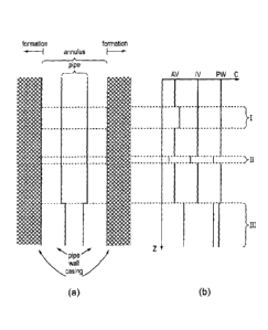
7 Figure 10 illustrates in schematic form an example of the correlation
between changes in
8 acoustic mode data and changes in wellbore conditions.
CA 02841403 2014-01-09
WO 2013/008035 PCT/GB2012/051682
9
1 Detailed description of preferred embodiments
2
3 In a particular embodiment of the invention, described here in order to
provide an example
4 of a preferred implementation of the present invention, a plurality of
acoustic sensors is
provided in a distributed optical fibre sensor which comprises a length of
optical fibre ¨
6 located in a location or environment to be monitored as illustrated in
Figure 1. Examples
7 of such distributed sensor arrangements are described in Silixa Limited's
international
8 patent application publication numbers W02010/136809A2 and
W02010/136810A2 and in
9 further detail below. Using such interferometers as an optical sensor, it
is possible to
make measurements of acoustic phase, frequency and amplitude from an optical
sensor
11 with high sensitivity, high speed of measurement and a large dynamic
range.
12
13 With reference to Figure 1, light emitted by a laser (21) is modulated
by a pulse signal
14 (22). An optical amplifier (25) is used to boost the pulsed laser light,
and this is followed
by a band-pass filter (26) to filter out the Amplified Spontaneous Emission
noise (ASE) of
16 the amplifier. The optical signal is then sent to an optical circulator
(27). An additional
17 optical filter (28) may be used at one port of the circulator (27). The
light is sent to sensing
18 fibre (32), which is for example a single mode fibre or a multimode
fibre. A length of the
19 fibre may be isolated and used as a reference section (30), for example
in a "quiet"
location or with a controlled reference signal. The reference section (30) may
be formed
21 between reflectors or a combination of beam splitters and reflectors
(29) and (31). The
22 reflected and the backscattered light generated along the sensing fibre
(32) is directed
23 through the circulator (27) and into the interferometer (33).
24
Within the interferometer, the incoming light is amplified in an optical
amplifier (1), and
26 transmitted to the optical filter (2). The filter (2) filters the out of
band ASE noise of the
27 amplifier (1). The light then enters into an optical circulator (3)
which is connected to a 3x3
28 optical coupler (4). A portion of the light is directed to the
photodetector (12) to monitor the
29 light intensity of the input light. The other portions of light are
directed along first and
second optical paths (5) and (6), with a path length difference between the
two paths.
31 Faraday-rotator mirrors (FRMs) (7) and (8) reflect the light back
through the first and
32 second paths (5) and (6), respectively. The Faraday rotator mirrors
provide self-
33 polarisation compensation along optical paths (5) and (6) such that the
two portions of light
34 efficiently interfere at each of the 3x3 coupler (4) ports. The optical
coupler (4) introduces
relative phase shifts of 0 degrees, +120 degrees and -120 degrees to the
interference
CA 02841403 2014-01-09
WO 2013/008035 PCT/GB2012/051682
1 signal, such that first, second and third interference signal components
are produced, each
2 at a different relative phase.
3
4 First and second interference signal components are directed by the
optical coupler (4) to
5 photodetectors (13) and (14), and the third interference signal component
incident on the
6 optical circulator (3) is directed towards photodetector (15).
7
8 The photodetectors (12), (13), (14) and (15) convert the light into
electrical signals. The
9 electrical signals are digitised and then the relative optical phase
modulation along the
10 reference fibre (30) and the sensing fibre (32) is computed using a fast
processor unit (34).
11 The processor unit is time synchronised with the pulse signal (22). The
path length
12 difference between path (5) and path (6) defines the spatial resolution,
and the origin of
13 the backscattered light (i.e. the position of the measured condition) is
derived from the
14 timing of the measurement signal. Rapid measurement is made possible by
measuring
light intensity only.
16
17 Methods for calculating the relative phase and amplitude from three
phase shifted
18 components of an interference signal are known from the literature. For
example,
19 Zhiqiang Zhao et al. ("Improved Demodulation Scheme for Fiber Optic
Interferometers
Using an Asymmetric 3x3 Coupler", J. Lightwave Technology, Vol.13, No.11,
November
21 1997, pp. 2059 ¨ 2068) and Huang et al (US 5,946,429) describe
techniques for
22 demodulating the outputs of 3x3 couplers in continuous wave multiplexing
applications.
23
24 The phase angle data (or relative phase) is sensitive to acoustic
perturbations experienced
by the sensing fibre. As an acoustic wave passes through the optical fibre, it
causes the
26 glass structure to contract and expand. This varies the optical path
length between the
27 backscattered light reflected from two locations in the fibre (i.e. the
light propagating down
28 the two paths in the interferometer), which is measured in the
interferometer as a relative
29 phase change. In this way, the optical phase angle data can be processed
to measure the
acoustic signal at the point at which the light is reflected or backscattered.
The result is
31 that the true acoustic field can be measured at any and/or all points
along the fibre.
32
33 It is a key benefit of this "iDAS" system that, in comparison to
previous technologies which
34 consist of distributed point sensors or require special components such
as fibre gratings, it
is possible to obtain a continuum of acoustic signal measurements along a
length of
CA 02841403 2014-01-09
WO 2013/008035 PCT/GB2012/051682
11
1 optical fibre. However, in practical terms, measurements will typically
be performed at a
2 spacing (i.e. resolution) of 1 metre over several thousand metres of
optical fibre. A key
3 application is in the monitoring of in-well (and out-of-well) acoustic
signals, where an
4 optical fibre is deployed within a well and iDAS employed to measure, in
real-time, sound
as a function of depth. Note that fibres can be deployed retrospectively for
this purpose,
6 although it is common for fibre optic cables to have already be deployed
in permanent
7 installations which iDAS can simply be coupled to.
8
9 From iDAS measurements taken over a period of time, it is possible to
derive a measure of
the speed of sound corresponding to a particular acoustic signal at a
particular position
11 along the fibre (and hence at a particular depth in a well).
12
13 It will of course be understood that the concepts and applications
presented in the
14 following description in the context of upstream measurements (e.g.
within production and
injection wells), will apply equally to midstream (e.g. within flowlines and
pipelines) and
16 downstream (e.g. within refineries and petrochemical plants)
measurements, as well as a
17 host of other applications, in the energy field and other fields, that
will be readily apparent
18 to the skilled reader. Furthermore, while iDAS is the preferred
measurement system for
19 obtaining acoustic measurements, it will be understood that the concepts
will apply equally
to other distributed acoustic measurement systems.
21
22 As described briefly above, Figure 2 illustrates how the speed of sound
within a tubular is
23 affected by the composition of the fluid within the tubular. It is
evident from the trace below
24 the tubular that the presence of a gas (e.g. in air bubbles as
illustrated or in the event of
outgassing) will result in a localised reduction in the speed of sound, and
that in contrast
26 the presence of a dense or particulate material (e.g. a hydrate clump)
will result in a
27 localised increase in the speed of sound. Importantly, it should be
realised that
28 conventional acoustic detection techniques, such as the use of
hydrophones or fibre
29 gratings, may be useful for implementing this technology but may not
provide sufficient
spatial resolution or be adequately positioned to identify highly localised
occurrences such
31 as these that might relate to unfavourable (or perhaps favourable)
developments within the
32 well. On this basis, iDAS provides a sensitive means of performing
distributed flow
33 monitoring including fluid composition monitoring such as determining
liquid to gas ratio
34 (as described in Silixa Limited's international patent application
publication numbers
W02010/136809A2 and W02010/136810A2).
CA 02841403 2014-01-09
WO 2013/008035 PCT/GB2012/051682
12
1
2 Figure 3 illustrates how the speed of sound within a tubular is also
affected by the direction
3 of propagation of the sound wave or, to put it another way, the relative
direction of the fluid
4 flow within the tubular. Also illustrated, schematically, are eddies
which in addition to
contributing to localised variations in the speed of sound will generally move
in the
6 direction of fluid flow. Using iDAS, these eddies can be tracked in real-
time. Accordingly,
7 further or alternative bases for distributed flow monitoring are
provided.
8
9 Figure 4 shows as schematic data to enhance features (top) the speed of
upward-
travelling sound waves within a well as a function of depth and (bottom) the
speed of
11 downward-travelling soundwaves within a well as a function of depth. For
actual
12 calculations a colour map provides additional information of intensity
(i.e. amplitude), with
13 red indicating strongest signal power and blue indicating weakest signal
power. From
14 these graphs, it is possible to determine characteristics and/or
diagnostic information
about the well. These characteristics have been determined for actual wells
with greater
16 detail than shown here.
17
18 For example, it can be observed from Figure 4 that (aside from the
discontinuities) the
19 sound speed varies generally linearly with depth, which is consistent
with the expected
variations in speed of sound in deep waters. In the deep isothermal layer,
temperature
21 and salinity are substantially uniform and as such the speed of sound
varies only with
22 pressure.
23
24 However, as noted above there are several discontinuities in the plots.
In the upward-
travelling sound waves plot there is a discontinuity at position X above which
the velocity is
26 ¨1500 m.5-1 and below which the velocity is ¨1300 m.5-1. Furthermore,
there is a
27 significant discontinuity at position Y. This discontinuity has been
found to correspond to a
28 change in casing cross-section.
29
31 The discontinuity corresponds to a change between a larger (7") diameter
inner pipe and a
32 smaller (5.5") diameter pipe. Accordingly, the speed of sound
measurement provides a
33 mechanism for measuring said pipe diameter, or at least for detecting
changes in pipe
34 diameter.
13
It is noted that in some regions, multiple coincident sound speeds are
visible. Lea and
Kyllingstad ("Propagation of Coupled Pressure Waves in Borehole with
Drillstring", International
Conference on Horizontal Well Technology, SPE37156 pp. 963-970, 1996, DOI
10.2118/37156-
MS) describe the physics of a coupled system in which waves within the drill
string
communicate within the annulus as a result of the annular flexibility of the
drill string and of the
formation. In cross-section, this is analogous to the pipe within a cased
borehole (as illustrated
in cross-section in Figure 5). Accordingly, it is possible to derive the
equations of motion for the
inner fluid volume (i.e. the fluid within the pipe), the pipe itself, and the
outer fluid volume (i.e.
the fluid in the annulus between the pipe and the casing).
The skilled person will readily appreciate that equivalent equations of motion
may be derived for
any multi degree of freedom oscillating system and therefore that the
invention is applicable to
systems other than systems comprised of a pipe within cased borehole. However
the invention
will be further described in the context of such a system in order to provide
an illustrative
example with real data obtained through experiment.
In this example, analysis has shown that the fluid pressure communication
between the inner
fluid volume, the pipe, and the outer fluid volume leads to the presence of a
coupled mode
system containing three modes, each of which consists of three waves. The
first wave is
predominantly within the inner fluid volume, the second wave is predominantly
within the walls
of the pipe, and the third wave is predominantly in the outer fluid volume.
Based on the well
geometries in the vicinity of the change in cross-section at position Y the
mode shapes and
velocities can be determined and are illustrated in Figure 6.
Figure 6 demonstrates the presence of said three mode shapes each consisting
of three
different waves. The first (Mode 1 ¨ top) consists of a pressure wave with a
dominant presence
in the inner fluid volume. The second (Mode 2 ¨ middle) consists of a strain
wave in the wall of
the pipe itself. The third (Mode 3 ¨ bottom) consists of another pressure wave
with a dominant
presence in the annular fluid volume.
Based on this information, it is possible to determine the root of the
coincident sound speeds
evident in Figure 4. In region Z the slower-propagating wave is a pressure
wave predominantly
in the annular fluid volume and the faster-propagating wave is a pressure wave
predominantly in
the inner fluid volume.
CA 2841403 2019-08-13
CA 02841403 2014-01-09
WO 2013/008035 PCT/GB2012/051682
14
1 Note that employing the full 3-D elastodynamic solution for the geometry
of a pipe within a
2 borehole taught by Rao and Vandiver ("Acoustics of fluid-filled boreholes
with pipe: Guided
3 propagation and radiation", J. Acoust. Soc. Am. 105(6), pp 3057-3066,
1999) provides
4 more complete information relating to the system, such as the amplitude
of the signal in
the three regions (inner fluid volume, pipe, and annular fluid volume), the
relative
6 amplitudes of signals in different modes, dispersion characteristics and
the upper
7 frequency cut-off for the modal phenomena.
8
9 The modal phenomena will occur when the wavelength of the acoustic signal
is very long
in comparison to the diameter of the borehole. At higher frequencies the speed
of the
11 wave will be the same as the thermodynamic speed of propagation for the
unbounded fluid
12 ¨ which accounts for the presence of a wave moving at the speed of
propagation of sound
13 in water (-1500 m.5-1).
14
The sound-speed effects, i.e. coupled modes, observed in the distributed
acoustic
16 measurements described above have, until now, never been observed or
investigated in
17 relation to cased production or injection tubes. In observing and
analysing these
18 phenomena, the work performed by the Applicant has resulted in a
technique whereby
19 modal analysis can be used to determine information concerning the
formation or the fluid
in the annulus, for example by inverting the model against the actual acoustic
data. It also
21 enables real-time monitoring of the formation, particularly where
detailed information about
22 the formation is already available, because it will be understood that
acoustic energy from
23 the modes propagating within the annulus will also penetrate into the
formation.
24
By way of explanation, based on Rao & Vandiver's work, acoustic propagation
and
26 radiation in a particular well can be modelled using full 3-D
elastodynamic equations and
27 various parameters of the well itself including the hardness of the
formation.
28
29 The Applicant has developed such a model of a pipe-in-pipe system, the
accuracy of
which has been confirmed against independent data on a well-known
installation.
31 Specifically, a measure of formation hardness has been obtained by
modifying the Rao &
32 Vandiver-based model to treat speed of sound as a known parameter and
formation
33 hardness as an unknown parameter. Accordingly, having established a
model with known
34 parameters it is in a similar way possible to determine other unknown
parameters (or
CA 02841403 2014-01-09
WO 2013/008035 PCT/GB2012/051682
1 indeed look for discrepancies or changes in said known parameters) based
on the
2 measured speed(s) of sound.
3
4 To illustrate the above, Figure 10 provides, in schematic form, (a) an
example section of
5 pipe within a wellbore with a number of features (or defects), alongside
(b) a
6 corresponding trace of speed of speed of sound versus distance. In this
example, three
7 acoustic modes are present, corresponding to a mode within the annular
volume (AV), the
8 inner volume (IV) and the pipe wall (PW). In region I, there is a
discontinuity that affects
9 substantially only the acoustic mode propagating in the annular volume.
In this example
10 this corresponds to a local increase in formation hardness. Similarly,
there is a
11 discontinuity in all three acoustic modes in region II, in this example
corresponding to
12 some damage to the wall of the pipe. Finally, in region III there is a
narrowing of the inner
13 pipe diameter which again affects the local speed of sound of all three
modes. It will now
14 be evident that while the model may be used to predict acoustic mode
behaviour, the
15 acoustic mode data can in fact be used to determine unknown parameters
of the wellbore.
16
17 Note that the above example is described for the purposes of
illustration only and the
18 relative speeds and the nature and extent of the acoustic
discontinuities are suggested
19 and exaggerated to aid understanding of the invention.
21 Figure 7 shows schematically speed of sound as a function of depth
(again in both
22 directions supported by the waveguide) for four separate example wells,
in a similar
23 manner to the way in which corresponding data was presented in Figure 4
(see above). In
24 these graphs it will be noted (particularly in the cases of (b) Well B
and (c) Well C) that
there again exist spatially simultaneous different acoustic modes (propagating
at different
26 speeds), some of which are associated with discontinuities (e.g. see the
top graph of (b)
27 Well B). Note that the thick red lines indicate the pipe diameter as a
function of depth and,
28 importantly, changes in pipe diameter which can be seen to correspond
with
29 discontinuities and other phenomena in the measured speed of sound.
White lines are
used to denote the separate modes, which are also identified by labels.
31
32 Figure 8 shows the peak quality of the data presented in Figure 7, in
which the speed data
33 has been averaged along the entire depth of each well and subsequently
normalised.
34 The presence of the distinct modes (in (b) Well B and (c) Well C), and
the relative
strengths and profiles therebetween, are evident from these plots.
CA 02841403 2014-01-09
WO 2013/008035 PCT/GB2012/051682
16
1
2 As before, these measurements confirm the assertions above that changes
in pipe
3 diameter result in changes in modal behaviour which can be observed to
glean more
4 information about the behaviour of fluid flow on the region of the pipe
diameter change. Of
course, modal behaviour may be observed in other situations. It will also be
appreciated
6 that changes in the formation will also affect the modes and as such
these can be
7 employed to monitor the formation as well as in-well conditions. For
example, Figure 9
8 illustrates the flow as a function of depth as calculated from the speeds
of sound detected
9 and the different modes detected. From this information, it is possible
to determine the
speed of sound and other parameters relating to the annular fluid volume as
well as the
11 inner fluid volume.
12
13 As can be appreciated, analysis of the various modes found within the
acoustic
14 measurements performed with an iDAS (or equivalent) apparatus provides a
sensitive and
high resolution method for studying or monitoring well integrity. For example,
in addition to
16 tracking eddies, observing events such as outgassing or the presence of
solids such as
17 sand or other particulate material, it is possible to make a
determination of the hardness of
18 the formation itself.
19
The invention relates to the use of distributed optical fibre sensors for
distributed acoustic
21 sensing, and in particular, modal analysis of distributed acoustic data
obtained in-well to
22 monitoring well integrity. By determining one or more acoustic modes
corresponding to
23 distributed speed of sound measurements within the wellbore, and
analysing variations in
24 the distributed speed of sound measurement it is possible to derive
information relating to
a formation and/or fluid in the wellbore.
26
27 Throughout the specification, unless the context demands otherwise, the
terms 'comprise'
28 or 'include', or variations such as 'comprises' or 'comprising',
'includes' or 'including' will be
29 understood to imply the inclusion of a stated integer or group of
integers, but not the
exclusion of any other integer or group of integers.
31
32 The foregoing description of the invention has been presented for the
purposes of
33 illustration and description and is not intended to be exhaustive or to
limit the invention to
34 the precise form disclosed. The described embodiments were chosen and
described in
order to best explain the principles of the invention and its practical
application to thereby
CA 02841403 2014-01-09
WO 2013/008035 PCT/GB2012/051682
17
1 enable others skilled in the art to best utilise the invention in various
embodiments and
2 with various modifications as are suited to the particular use
contemplated. Therefore,
3 further modifications or improvements may be incorporated without
departing from the
4 scope of the invention as defined by the appended claims.