Sélection de la langue

Search

Sommaire du brevet 2850556 

Énoncé de désistement de responsabilité concernant l'information provenant de tiers

Une partie des informations de ce site Web a été fournie par des sources externes. Le gouvernement du Canada n'assume aucune responsabilité concernant la précision, l'actualité ou la fiabilité des informations fournies par les sources externes. Les utilisateurs qui désirent employer cette information devraient consulter directement la source des informations. Le contenu fourni par les sources externes n'est pas assujetti aux exigences sur les langues officielles, la protection des renseignements personnels et l'accessibilité.

Disponibilité de l'Abrégé et des Revendications

L'apparition de différences dans le texte et l'image des Revendications et de l'Abrégé dépend du moment auquel le document est publié. Les textes des Revendications et de l'Abrégé sont affichés :

  • lorsque la demande peut être examinée par le public;
  • lorsque le brevet est émis (délivrance).
(12) Brevet: (11) CA 2850556
(54) Titre français: OSCILLATEUR ULTRASONORE
(54) Titre anglais: ULTRASONIC OSCILLATOR
Statut: Octroyé
Données bibliographiques
(51) Classification internationale des brevets (CIB):
  • B01J 19/10 (2006.01)
  • A23L 29/281 (2016.01)
(72) Inventeurs :
  • HUANG, LYNN L. H. (Chine)
(73) Titulaires :
  • HUANG, LYNN L. H. (Chine)
(71) Demandeurs :
  • HUANG, LYNN L. H. (Chine)
(74) Agent: ADE & COMPANY INC.
(74) Co-agent:
(45) Délivré: 2016-06-21
(86) Date de dépôt PCT: 2012-09-05
(87) Mise à la disponibilité du public: 2013-03-14
Requête d'examen: 2014-03-31
Licence disponible: S.O.
(25) Langue des documents déposés: Anglais

Traité de coopération en matière de brevets (PCT): Oui
(86) Numéro de la demande PCT: PCT/CN2012/001242
(87) Numéro de publication internationale PCT: WO2013/033973
(85) Entrée nationale: 2014-03-31

(30) Données de priorité de la demande:
Numéro de la demande Pays / territoire Date
61/531,438 Etats-Unis d'Amérique 2011-09-06

Abrégés

Abrégé français

L'invention porte sur un oscillateur ultrasonore pour fabriquer une matrice de collagène, qui comprend un corps creux (10), une rainure de réception (20), un composant de transmission (30), de multiples cadres (40), de multiples dispositifs oscillants (50) et un mécanisme ultrasonore (60). La rainure de réception (20) est disposée dans le corps (10). Le cadre (40) est relié au composant de transmission (30). Le composant de transmission (30) commande au cadre (40) de s'éloigner de ou d'être reçu dans la rainure de réception (20). Les dispositifs oscillants (50) sont reliés respectivement aux cadres (40). Le mécanisme ultrasonore (60) est agencé dans la rainure de réception (20). Durant le traitement, les dispositifs oscillants (50) et le mécanisme ultrasonore (60) agissent sur le tissu conjonctif dans la rainure de réception (20), de sorte que le tissu conjonctif devienne progressivement une matrice de collagène.


Abrégé anglais

An ultrasonic oscillator for manufacturing a collagen matrix comprises a hollow body (10), a receiving groove (20), a transmission component (30), multiple frames (40), multiple oscillation devices (50) and an ultrasonic mechanism (60). The receiving groove (20) is provided in the body (10). The frame (40) is connected to the transmission component (30). The transmission component (30) drives the frame (40) to move away from or to be received in the receiving groove (20). The oscillating devices (50) are respectively connected to the frames (40). The ultrasonic mechanism (60) is arranged in the receiving groove (20). During the process, the oscillating devices (50) and the ultrasonic mechanism (60) act on the connective tissue in the receiving groove (20), so that the connective tissue gradually becomes a collagen matrix.

Revendications

Note : Les revendications sont présentées dans la langue officielle dans laquelle elles ont été soumises.


6
CLAIMS
1. An ultrasonic oscillator for manufacturing porous collagen matrices, the

ultrasonic oscillator comprising:
a hollow body;
a receiving groove mounted securely in the body;
a transmission component mounted through the body, and having
a hydraulic cylinder;
a cover connected to the hydraulic cylinder and selectively sealing the
receiving
groove;
multiple supporting rods for providing vibration, and mounted through a top of
the
body and the cover, and connected to the hydraulic cylinder;
multiple frames connecting to the transmission component, respectively hung on
the
supporting rods, and selectively mounted in the receiving groove by the
transmission
component, and each frame having multiple containers inserted therein;
multiple oscillation devices connecting to and selectively vibrating a
corresponding
frame; and
an ultrasonic mechanism mounted in the receiving groove.
2. The ultrasonic oscillator as claimed in claim 1, wherein the hydraulic
cylinder is
mounted on the top of the body.
3. The ultrasonic oscillator as claimed in claim 1 or 2, wherein each
oscillation
device comprises a spur gear mounted securely on one of the supporting rods; a
motor
mounted on the body; and an eccentric gear driven by the motor and selectively
engaging the
spur gear.
4. The ultrasonic oscillator as claimed in any one of claims 1 to 3 further

comprising a vacuum pump mounted on the cover, wherein the cover has a
pressure relief
device mounted thereon.
5. The ultrasonic oscillator as claimed in any one of claims 1 to 3 further

comprising a spraying mechanism mounted in the receiving groove, wherein the
receiving
groove has a discharging pipe mounted on a bottom of the receiving groove and
protruding
out of the body.
6. The ultrasonic oscillator as claimed in claim 4 further comprising a
spraying
mechanism mounted in the receiving groove, wherein the receiving groove has a
discharging
pipe mounted on a bottom of the receiving groove and protruding out of the
body.

Description

Note : Les descriptions sont présentées dans la langue officielle dans laquelle elles ont été soumises.

CA 02850556 2015-10-19
1
AN ULTRASONIC OSCILLATOR
BACKGROUND OF THE INVENTION
1. Field of the Invention
The present invention relates to an ultrasonic oscillator, especially to an
ultrasonic
oscillator for manufacturing porous collagen matrices.
2. Description of the Prior Arts
Collagen is widely used in modern society. Biotechnology industry endeavors to
manufacture collagen faster with good quality. Therefore, manufacturing porous
collagen
- matrices from connective tissues accordingly becomes an important issue.
SUMMARY OF THE INVENTION
A main aspect of the present invention is to provide an ultrasonic oscillator
for
manufacturing porous collagen matrices.
To achieve above, the present invention develops an ultrasonic oscillator
comprising:
a hollow body;
a receiving groove mounted securely in the body;
a transmission component mounted through the body;
multiple frames connecting to the transmission component and selectively
mounted in
the receiving groove, and each frame having multiple containers inserted
therein;
multiple oscillation devices connecting to and selectively vibrating a
corresponding
frame; and
an ultrasonic mechanism mounted in the body.
According to an aspect of the invention, there is provided an ultrasonic
oscillator for
manufacturing porous collagen matrices, the ultrasonic oscillator comprising:
a hollow body;
a receiving groove mounted securely in the body;
a transmission component mounted through the body, and having
a hydraulic cylinder;
a cover connected to the hydraulic cylinder and selectively sealing the
receiving
groove;

CA 02850556 2015-10-19
la
multiple supporting rods for providing vibration, and mounted through a top of
the
body and the cover, and connected to the hydraulic cylinder;
multiple frames connecting to the transmission component, respectively hung on
the
supporting rods, and selectively mounted in the receiving groove by the
transmission
component, and each frame having multiple containers inserted therein;
multiple oscillation devices connecting to and selectively vibrating a
corresponding
frame; and
an ultrasonic mechanism mounted in the receiving groove.

CA 02850556 2014-03-31
2
1 The ultrasonic oscillator as described, wherein the transmission
2 component comprises a hydraulic cylinder mounted on the top of the body;
a
3 cover connected to the hydraulic cylinder and selectively sealing the
receiving
4 groove; and multiple supporting rods mounted vibratile through the top of
the
body and the cover and connected to the hydraulic cylinder; and the frames are
6 respectively hung on the supporting rods.
7 The ultrasonic oscillator as described, wherein each oscillation device
8 comprises a spur gear mounted securely on the corresponding supporting
rod; a
9 motor mounted on the body; and an eccentric gear driven by the motor and
selectively engaging the spur gear.
11 The ultrasonic oscillator as described further comprising a vacuum
12 pump mounted on the cover, wherein the cover has a pressure relief
device
13 mounted thereon.
14 = The ultrasonic oscillator as described further comprising a vacuum
pump mounted on the cover, wherein the cover has a pressure relief device
16 mounted thereon.
17 The ultrasonic oscillator as described further comprising a spraying
18 mechanism mounted in the receiving groove, wherein the receiving groove
has
19 a discharging pipe mounted on a bottom of the receiving groove and
protruding
out of the body.
21 The present invention has following advantages. With the cooperation
22 between the oscillation devices and the ultrasonic mechanism, the
connective
23 tissues in the containers gradually become porous collagen matrices to
be
24 provided for the needs of the industry

CA 02850556 2014-03-31
3
1 BRIEF DESCRIPTION OF THE DRAWINGS
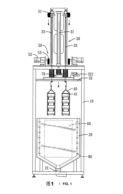
2 Fig. 1 is an operational front view of an ultrasonic oscillator for
3 manufacturing porous collagen matrices, showing the frames being moved
into
4 the receiving groove;
Fig. 2 is an enlarged side view of a container of the ultrasonic oscillator
6 in Fig. 1;
7 Fig. 3 is an operational front view of the ultrasonic oscillator in Fig.
1,
8 showing the frames oscillating; and
9 Fig. 4 is another operational front view of the ultrasonic oscillator in
Fig. 1, showing the frames oscillating.
11 DETAILED DESCRIPTION OF THE PREFERRED EMBODIMENTS
12 With the drawings and the preferred embodiment in accordance with
13 the present invention as follow, the means to achieve the purpose of the
present
14 invention will be understood and appreciated more fully.
With reference to Fig. 1, an ultrasonic oscillator in accordance with the
16 present invention comprises a hollow body 10, a receiving groove 20, a
17 transmission component 30, multiple frames 40, multiple oscillation
devices 50,
18 an ultrasonic mechanism 60, a vacuum pump 70 and a spraying mechanism
80.
19 The receiving groove 20 is mounted securely in the body 10 and is
mounted near a bottom of the body 10. The receiving groove 20 has a
21 discharging pipe 21 mounted on a bottom of the receiving groove 20 and
22 protruding out of the body 10.
23 The transmission component 30 is mounted through a top of the body
24 10 and comprises a hydraulic cylinder 31, a cover 32 and multiple
supporting

CA 02850556 2014-03-31
4
1 rods 33. The hydraulic cylinder 31 is mounted on the top of the body 10.
The
2 cover 32 is connected to the hydraulic cylinder 31, selectively seals the
3 receiving groove 20 and has a pressure relief device 321 mounted thereon.
The
4 supporting rods 33 are mounted vibratile through the top of the body 10
and the
cover 32 and are connected to the hydraulic cylinder 31.
6 With reference to Figs. 1 and 2, the frames 40 connect to the
7 transmission component 30 and are selectively mounted in the receiving
groove
8 20. In a preferred embodiment, the frames 40 are respectively hung on the
9 supporting rods 33. Each frame 40 has multiple containers 41 inserted
therein.
Each container 41 has multiple holes 411 formed therethrough.
11 Each oscillation device 50 connects to and selectively vibrates a
12 corresponding frame 40 and comprises a spur gear 51, a motor 52 and an
13 eccentric gear 53. The spur gear 51 is mounted securely on the
corresponding
14 supporting rod 33. The motor 52 is mounted on the body 10. The eccentric
gear
53 is driven by the motor 52 and selectively engages the spur gear 51.
16 The ultrasonic mechanism 60 is mounted in the body 10.
17 The vacuum pump 70 is mounted on the cover 32 and selectively
18 extracts the air in the receiving groove 20 to create vacuum in the
receiving
19 = groove 20.
The spraying mechanism 80 is mounted in the receiving groove 20 and
21 selectively sprays water to moisten the subjects in the containers 41.
The water
22 sprayed into the receiving groove 20 is discharged out from the
discharging
23 pipe 21. The spraying mechanism 80 may comprise multiple nozzles.
24 With reference to Figs. 1 and 2, connective tissues 90 are put in
the

CA 02850556 2014-03-31
1 containers 41. The hydraulic cylinder 31 pushes the cover 32 to move
2 downward and seals the receiving groove 20 and the frames 40 are also
moved
3 into the receiving groove 20. The vacuum pump 70 may create vacuum in the
4 receiving groove 20 when the cover 32 seals the receiving groove 20.
5 With reference to Figs. 3 and 4, the eccentric gears engage the spur
6 gears 51. The motors 52 operate and the eccentric gears 53 are rotated to
drive
7 the spur gears 51 to rotate and oscillate. Therefore, the supporting rods
33
8 oscillate to vibrate the frames 40 and containers 41. The ultrasonic
mechanism
9 60 and the spraying mechanism 80 also operate. Then the connective
tissues in
the containers 41 gradually become porous collagen matrices.
11 When the manufacturing process is finished, the pressure relief device
12 321 is operated to allow the air to infuse into the receiving groove 20.
Then the
13 hydraulic cylinder 31 pulls the cover 32 and the frames 40 to move
upward and
14 leave the receiving groove 20. Then the manufacturer may take the
containers
41 out of the frames 40.
16 Even though numerous characteristics and advantages of the present
17 invention have been set forth in the foregoing description, together
with details
18 of the structure and features of the invention, the disclosure is
illustrative only.
19 Changes may be made in the details, especially in matters of shape,
size, and
arrangement of parts within the principles of the invention to the full extent
21 indicated by the broad general meaning of the terms in which the
appended
22 claims are expressed.
23

Dessin représentatif
Une figure unique qui représente un dessin illustrant l'invention.
États administratifs

Pour une meilleure compréhension de l'état de la demande ou brevet qui figure sur cette page, la rubrique Mise en garde , et les descriptions de Brevet , États administratifs , Taxes périodiques et Historique des paiements devraient être consultées.

États administratifs

Titre Date
Date de délivrance prévu 2016-06-21
(86) Date de dépôt PCT 2012-09-05
(87) Date de publication PCT 2013-03-14
(85) Entrée nationale 2014-03-31
Requête d'examen 2014-03-31
(45) Délivré 2016-06-21

Historique d'abandonnement

Il n'y a pas d'historique d'abandonnement

Taxes périodiques

Dernier paiement au montant de 125,00 $ a été reçu le 2023-06-19


 Montants des taxes pour le maintien en état à venir

Description Date Montant
Prochain paiement si taxe applicable aux petites entités 2024-09-05 125,00 $
Prochain paiement si taxe générale 2024-09-05 347,00 $

Avis : Si le paiement en totalité n'a pas été reçu au plus tard à la date indiquée, une taxe supplémentaire peut être imposée, soit une des taxes suivantes :

  • taxe de rétablissement ;
  • taxe pour paiement en souffrance ; ou
  • taxe additionnelle pour le renversement d'une péremption réputée.

Les taxes sur les brevets sont ajustées au 1er janvier de chaque année. Les montants ci-dessus sont les montants actuels s'ils sont reçus au plus tard le 31 décembre de l'année en cours.
Veuillez vous référer à la page web des taxes sur les brevets de l'OPIC pour voir tous les montants actuels des taxes.

Historique des paiements

Type de taxes Anniversaire Échéance Montant payé Date payée
Requête d'examen 400,00 $ 2014-03-31
Rétablissement des droits 200,00 $ 2014-03-31
Le dépôt d'une demande de brevet 200,00 $ 2014-03-31
Taxe de maintien en état - Demande - nouvelle loi 2 2014-09-05 50,00 $ 2014-04-02
Taxe de maintien en état - Demande - nouvelle loi 3 2015-09-08 50,00 $ 2015-08-24
Taxe finale 150,00 $ 2016-04-08
Taxe de maintien en état - brevet - nouvelle loi 4 2016-09-06 50,00 $ 2016-08-11
Taxe de maintien en état - brevet - nouvelle loi 5 2017-09-05 100,00 $ 2017-08-28
Taxe de maintien en état - brevet - nouvelle loi 6 2018-09-05 100,00 $ 2018-06-25
Taxe de maintien en état - brevet - nouvelle loi 7 2019-09-05 100,00 $ 2019-08-26
Taxe de maintien en état - brevet - nouvelle loi 8 2020-09-08 100,00 $ 2020-09-03
Taxe de maintien en état - brevet - nouvelle loi 9 2021-09-07 100,00 $ 2021-05-19
Taxe de maintien en état - brevet - nouvelle loi 10 2022-09-06 125,00 $ 2022-06-14
Taxe de maintien en état - brevet - nouvelle loi 11 2023-09-05 125,00 $ 2023-06-19
Titulaires au dossier

Les titulaires actuels et antérieures au dossier sont affichés en ordre alphabétique.

Titulaires actuels au dossier
HUANG, LYNN L. H.
Titulaires antérieures au dossier
S.O.
Les propriétaires antérieurs qui ne figurent pas dans la liste des « Propriétaires au dossier » apparaîtront dans d'autres documents au dossier.
Documents

Pour visionner les fichiers sélectionnés, entrer le code reCAPTCHA :


Pour visualiser une image, cliquer sur un lien dans la colonne description du document. Pour télécharger l'image (les images), cliquer l'une ou plusieurs cases à cocher dans la première colonne et ensuite cliquer sur le bouton "Télécharger sélection en format PDF (archive Zip)" ou le bouton "Télécharger sélection (en un fichier PDF fusionné)".

Liste des documents de brevet publiés et non publiés sur la BDBC .

Si vous avez des difficultés à accéder au contenu, veuillez communiquer avec le Centre de services à la clientèle au 1-866-997-1936, ou envoyer un courriel au Centre de service à la clientèle de l'OPIC.


Description du
Document 
Date
(yyyy-mm-dd) 
Nombre de pages   Taille de l'image (Ko) 
Paiement de taxe périodique 2020-09-03 1 33
Abrégé 2014-03-31 1 22
Revendications 2014-03-31 2 48
Dessins 2014-03-31 4 84
Description 2014-03-31 5 180
Dessins représentatifs 2014-03-31 1 19
Page couverture 2014-05-20 2 45
Description 2015-10-19 6 197
Revendications 2015-10-19 1 43
Page couverture 2016-05-03 2 46
Paiement de taxe périodique 2018-06-25 1 33
Paiement de taxe périodique 2019-08-26 1 33
PCT 2014-03-31 14 461
Cession 2014-03-31 9 158
Taxes 2014-04-02 1 28
Poursuite-Amendment 2015-04-30 4 254
Modification 2015-10-19 10 334
Taxe finale 2016-04-08 2 51