Note : Les descriptions sont présentées dans la langue officielle dans laquelle elles ont été soumises.
CA 02851454 2014-05-06
1
TURBOMACHINE STATOR INTERNAL SHELL WITH ABRADABLE MATERIAL
Field of the invention
[0001] The invention relates to an axial turbomachine fitted with a
compressor.
More specifically the invention relates to a compression stage for an axial
turbomachine compressor. More specifically the invention relates to the
sealing of a compression stage for an axial turbomachine compressor.
Background
[0002] An axial turbomachine compressor usually has several compression
stages, each of which is formed by the combination of a rotor blade row
and a stator blade row. In order to channel the flow axially in the
compression stage, the latter has coaxial shells. In particular, each stator
blade row is provided with an internal shell which is fixed to the inner tips
of the stator blades. Such an inner shell has an annular shape and
surrounds the rotor. Some functional play where they join is part of the
design.
[0003] In operation, leakage can occur between the rotor and the inner shell
because of this play. This leakage tends to reduce the effective
compression of each compression stage and reduces the pressure at the
compressor outlet. To enhance the output pressure axial turbomachines
compressors are fitted with seals. These devices can be fitted at each
compression stage, at the interface between the inner shell and the rotor.
[0004] They may include an annular layer of abradable material which is
advantageously fitted on the stator in order to reduce the rotating mass.
This is intended to mate abrasively with lip seals or annular slats which are
formed on the outer surface of the rotor. To save material, the layer of
abradable material can be divided into two annular layers. They are
arranged upstream and downstream of the inner shell. The latter may
have the shape of an inverted "U", the inner ends of the branches of which
support layers of abradable material. This "U" shape is a recess which
saves weight.
CA 02851454 2014-05-06
2
[0005] US Patent 7695244 B2 discloses a bladed compressor with an inner shell.
The latter is formed with a central platform and two radial extensions
terminating in return walls. The return walls each have annular bands of
abradable material that are intended to come into contact with the lip seals
formed on a radial rotor. The platform, the extensions and the return walls
define a cavity that is large in comparison with that defined between the lip
seals. This cavity configuration forms a reservoir to stem a localized and
short leak. However, it is not possible to significantly improve the seal
between the inner shell and the rotor during steady state operation.
Summary of the invention
[0006] The invention aims to solve at least one of the technical problems
presented by the prior art. In embodiments, the invention aims to increase
the outlet pressure of an axial compressor fitted with stators with internal
shells mating with the outer surface of the rotor. More specifically,
embodiments of the invention aim to reduce leaks in a compression stage
of an axial compressor. Embodiments of the invention also aim to lighten
the compressor of an axial turbomachine.
[0007] The invention relates to a compressor stage of an axial turbomachine,
comprising a rotor whose outer surface has at least two lip seals, each
forming a radial annular rib; and a stator which includes an annular array
of stator blades extending essentially radially; and an inner shell whose
radial section comprises a central part connected to the inner tips of the
blades, a lateral part extending from each side of the central part to at
least one of the two lip seals, respectively, thereby forming an annular
cavity with the rotor; wherein the shell and the rotor are designed so that
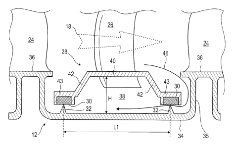
the radial section of the annular cavity has a length Li and a height H, the
length Li being greater than the height H.
[0008] The length Li of the radial section of the cavity is measured along the
axis
of rotation of the compression stage, the height H of the radial section of
the cavity is measured radially.
[0009] The annular cavity is a chamber in which a circular flow is generated
by
the outer rotor surface. The speed of the circular flow allows the pressure
CA 02851454 2014-05-06
3
to be lowered so as reduce leakage to the outside. Furthermore, the
elongated shape of the radial section of the annular cavity serves to damp
small localised leaks that may attempt to pass back beneath the inner
shell. The elongated shape of the annular cavity can increase the
efficiency of the motion of the air therein. By reducing the height of the
cavity relative to its length, the proportion of air set in motion in the
cavity
is increased as is the mean speed of this air.
[0010] According to an embodiment of the invention, the length Li of the
annular
cavity is greater than twice, preferably three times the height H of the said
cavity.
[0011] According to an embodiment of the invention, each of the lateral parts
has
an axial sub-part, the said sub-parts extending in opposite directions up to
their respective lip seals.
[0012] According to an embodiment of the invention the lateral parts diverge
from
each other from the central part towards the rotor.
[0013] According to an advantageous embodiment of the invention, the inner
shell is made of a composite material.
[0014] According to an embodiment of the invention, the height H of the
annular
cavity is constant over most of its length, preferably over 70% of its length,
more preferably over 80%.
[0015] According to an embodiment of the invention, the ends of the lateral
parts
have inner annular grooves designed to house a layer of abradable
material; preferably the annular grooves have inverted -U" or "L" sections;
preferably the stage comprises layers of abradable material fitted in the
annular grooves.
[0016] According to an embodiment of the invention, the inner tips of the
blades
extend inside the inner shell.
[0017] The lateral parts and/or the axial parts define annular chambers. These
annular chambers open onto one another and/or the cavity. Although they
are connected, the axial flow beneath the inner shell is slowed down by
circular bottlenecks demarcating these chambers and the annular cavity.
Thus, a flow that crosses them undergoes a series of pressure losses that
will hinder its progress.
CA 02851454 2014-05-06
4
[0018] The presence of the blades beneath the inner shell form aerodynamic
obstacles beneath the inner shell. In combination with the rotating flow in
the annular cavity which is drawn in by the rotor, new disturbances are
created. These increase the absolute speed of the fluid, which further
lowers the pressure.
[0019] According to an embodiment of the invention, the chords of the ends of
the
blades beneath the inner shell are inclined by more than 5 , preferably by
more than 10 , more preferably by more than 25 to the axis of rotation of
the rotor.
[0020] The inclination of the chords of the blades relative to the axis of
rotation of
the compressor force part of the flow to bypass the upstream part of the
blade beneath the inner shell. This flow also creates vortices which further
lower the pressure in the annular cavity.
[0021] According to an embodiment of the invention, the rotor has a wall with
a
profile of revolution which comprises a first part located opposite the inner
surface of the shell and a second part raised relative to the first part,
designed to provide support for fixing an annular rotor blade row, and a
joint connecting the first part to the second part, the second part at least
partially axially overlapping one of the lateral parts of the inner shell, the
wall preferably comprising a third part raised relative to the first part and
opposite the second part, the said third part axially overlapping at least
partially the other of the two lateral parts of the shell.
[0022] According to an embodiment of the invention, the third part axially
overlaps
the majority of the associated lateral part, preferably overlapping it by
more than 80%, more preferably it overlaps it by more than 95%.
[0023] According to an embodiment of the invention, the third part extends
axially
to the central part located opposite.
[0024] According to an embodiment of the invention, one of the lateral parts
extends axially up to the joint at a distance D2; preferably the joint is a
first
joint and the rotor wall profile comprises a second joint opposite the first
joint relative to the inner shell, the other of the two lateral parts of the
shell
extending axially to the second joint at a distance D2.
CA 02851454 2014-05-06
[0025] According to an embodiment of the invention, the height of the lip
seals is
less than 50%, preferably 30%, more preferably 15% of the height of the
lateral parts of the shell.
[0026] According to an embodiment of the invention, the outer surface of the
rotor
forming the annular cavity has a roughness Ra greater than 2 microns,
preferably greater than 6.4 microns, more preferably greater than 15
microns to cause air to be drawn into the said cavity. The surface
roughness Ra is the integral mean of the differences in absolute value.
[0027] According to an embodiment of the invention, the distance D3 between
the
inner tips of the stator blades and the rotor is equal to the thickness of the
layers of abradable materials measured at the lip seals; preferably the
distance D3 is substantially greater than the thickness of the layers of
abradable materials; preferably the distance D3 is between 0.50 mm and
5.00 mm.
[0028] According to an embodiment of the invention, the rotor comprises a wall
extending substantially axially between the lip seals.
[0029] The configuration of the compressor stage means the lips seals can be
shortened. When these are made of metal and the shell is made of
composite material the assembly becomes lighter.
[0030] According to an embodiment of the invention, the lateral parts are
designed to lightly graze the lip seals during the operation of the next
stage in accordance with predefined operating conditions.
[0031] According to an embodiment of the invention, the central part and the
lateral parts extend substantially in a straight line, the lateral parts being
inclined relative to the central part.
[0032] According to an embodiment of the invention, the lateral parts are
inclined
at more than 20 to the central part, preferably more than 45 , more
preferably more than 60 .
[0033] According to an embodiment of the invention, the shell is segmented.
[0034] According to an embodiment of the invention, the radial section of the
shell
is materially continuous.
CA 02851454 2014-05-06
6
[0035] According to an embodiment of the invention, the radial section of the
shell
is substantially thin; its thickness is less than 5.00 mm, preferably less
than 2.00 mm.
[0036] According to an embodiment of the invention, the outer surface of the
rotor
is substantially cylindrical or conical between the lip seals.
[0037] According to an embodiment of the invention, the distance D2 is between
1.00 mm and 10.00 mm, preferably between 2.00 mm and 5.00 mm.
[0038] According to an embodiment of the invention, the outer surfaces of the
third part of the rotor wall and the central part of the inner shell are
extensions of one another when in operation.
[0039] According to an embodiment of the invention, at rest the inner radial
ends
of the lateral parts extend axially up to the joint of the rotor wall profile,
preferably to less than 5.00 mm, more preferably to less than 2.00 mm,
more preferably to less than 0.50 mm.
[0040] According to an embodiment of the invention, the surface of the rotor
between the sets of lip seals is rough machined or sandblasted.
[0041] The invention also relates to an axial compressor having at least one
compression stage, wherein the compression stage is in accordance with
the invention.
[0042] The invention also relates to an axial turbomachine, such as a
turboprop,
comprising a compressor with at least one compression stage, wherein the
or at least one compression stage is in accordance with the invention.
[0043] According to an embodiment of the invention, the turbomachine includes
a
cylindrical housing extending axially along the length of the rotor, the rotor
comprises a one-piece drum and the housing essentially comprises two
half-shells, or the rotor and the housing both comprise axial segments
assembled axially.
[0044] The invention can reduce leakage between the inner shell and the rotor.
The shape of the annular cavity can dampen and slow down the progress
of a localised flow attempting to move upstream. Its elongated shape
increases the distance to be traversed in order to escape.
CA 02851454 2014-05-06
7
[0045] The extensions beneath the inner shell enable the circumferential flow
in
the annular cavity to be modified. Recirculation and the vortices formed
resist leakage by reducing the pressure in the cavity.
[0046] The choice of materials, combined with the architecture proposed by the
invention, is used to lighten the stage by reducing the quantity of resistive
materials that are required. The reduction in the height of the lip seals also
enables raw materials to be saved. Manufacturing costs can also be
reduced because axial access to the platforms is simplified in order, for
example, to undertake machining there.
Short description of the diagrams
[0047] Figure 1 shows an axial turbomachine in accordance with the invention.
[0048] Figure 2 shows a diagram of a turbomachine compressor according to the
invention.
[0049] Figure 3 illustrates a compression stage of a compressor according to a
first embodiment of the invention.
[0050] Figure 4 illustrates a compression stage of a compressor according to a
second embodiment of the invention.
[0051] Figure 5 is a sectional view of the stage, sectioned along axis 5-5
shown in
Figure 4.
[0052] Figure 6 is a view from the inside of an inner shell in accordance with
the
second embodiment of the invention.
Description of the embodiments
[0053] In the following description, the terms inner and outer refer to a
position
relative to the axis of rotation of an axial turbomachine.
[0054] Figure 1 shows an axial turbomachine. In this case it is a dual-flow
turboprop 2; it could also be a turbojet 2. The turboprop 2 comprises a first
compression stage, a so-called low-pressure compressor 4, a second
compression stage, a so-called high pressure compressor 6, a combustion
chamber 8 and one or more turbine stages 10. In operation, the
mechanical power of the turbine 10 is transmitted through the central shaft
to the rotor 12 and drives the two compressors 4 and 6. Reduction
mechanisms may increase the speed of rotation transmitted to the
CA 02851454 2014-05-06
8
compressors. Alternatively, the different turbine stages can each be
connected to the compressor stages through concentric shafts. These
latter comprise several rotor blade rows associated with stator blade rows.
The rotation of the rotor around its axis of rotation 14 generates a flow of
air and gradually compresses it up to the inlet of the combustion chamber
10.
[0055] An inlet fan, commonly designated a fan 16, is coupled to the rotor 12
and
generates an airflow which is divided into a primary flow 18 passing
through the various above-mentioned levels of the turbomachine, and a
secondary flow 20 passing through an annular conduit (shown in part)
along the length of the machine and then rejoins the main flow at the
turbine outlet. The primary flow 18 and secondary flow 20 are annular
flows and are channelled through the housing of the turbomachine. To this
end, the housing has cylindrical walls or shells that can be internal or
external.
[0056] Figure 2 is a sectional view of a low-pressure compressor 4 of an axial
turbomachine 2 such as that of Figure 1. Part of the turbofan 16 can be
seen, as can the splitter nose 22 between the primary 18 and secondary
20 airflows. The rotor 12 comprises several rows of rotor blades 24, for
example three. The low-pressure compressor 4 comprises several stators,
for example four, each of which has a row of stator blades 26.
[0057] At the inner ends of these latter is fixed an inner shell 28. It has a
general
shape of revolution such a tube. Its outer surface helps guide the primary
flow 18. To reduce leakage between the rotor 12 and a stator, layers of
abradable material 30 are located on the inner side of the inner shells 28.
These are intended to mate abrasively with the rotor 12 during operation.
Circular paths are dug in the layers of abradable material 30 by the rotor
and labyrinth seals are formed to improve sealing. The same material can
be used to form a seal between the outer tips of the rotor blades 24 and
the inner surface of the compressor housing.
[0058] The stators are associated with the fan 16 or a row of rotor blades for
straightening the airflow so as to convert the speed of the flow into
CA 02851454 2014-05-06
9
pressure. The combination of a stator and the fan 16 or a rotor blade row
together forms a compression stage.
[0059] The rotor 12 has a cylindrical shape, or that of a hollow drum. It has
a
substantially thin wall whose thickness may be generally less than 8.00
mm, preferably less than 5.00 mm, even more preferably less than 2.00
mm. The wall is rotationally symmetrical. Following an alternative
embodiment of the invention, the rotor may include disks with blades
around its circumference.
[0060] The rotor 12 may be made of a metallic material such as titanium or
aluminium. It can also be made of composite materials. It may be sized to
cater for deformations arising from, for example, the centrifugal forces
acting directly on it or that it undergoes via the rotor blades 24 it
supports.
Its expansion may also be taken into account.
[0061] Figure 3 is an illustration of a compression stage of the turbomachine
compressor 2 according to a first embodiment of the invention. The
compressor may be a low-pressure compressor. The rotor 12 includes an
integral drum, the stator comprising a housing formed by two half-shells
which are joined when the rotor is assembled.
[0062] The rotor wall is structural and has a shape of revolution. Its profile
of
revolution has parts which extend substantially radially or axially. It
comprises a first part 34 which extends axially and which is located facing
the inner surface of the inner shell 28. The profile of the shell also
includes
a second part 36 which extends substantially axially and which serves as a
mounting mechanism for the rotor blades 24. Upstream, the second part
36 axially overlaps the first part 34. The profile also has a joint 35
extending substantially radially and which connects the first part 34 and
the second part 36. The rotor has a profile shaped like the Greek letter II.
[0063] The shape of the wall enables inner and outer annular grooves to be
formed, the depth of the outer groove being such as to house the inner
shell 28 in its thickness. In this configuration, the outer surfaces of the
inner shell 28 and the second part 36 are extensions of one another.
[0064] The stage has a stator blade 26 and a rotor blade 24 located
downstream.
Taking into account other considerations, a stage can also be formed with
CA 02851454 2014-05-06
a rotor blade located upstream. The outer surface of the rotor 12 has
annular lip seals 32. They form annular ribs extending along the
circumference of the rotor 12 along a plane perpendicular to the axis of
rotation 14. The compression stage has essentially two sets of lip seals
32, one being located on the upstream side of the inner shell 28 and the
other on the downstream side. A set of lip seals may include one or more
lip seals.
[0065] The inner shell 28 comprises a substantially thin wall, which saves
weight.
It is advantageously made of a composite material in order to maximise
this weight saving while remaining rigid. It has a radial section with a
central part 40 and a lateral part 42 on each side. The central part 40 is
connected to the inner tip of the blade 26. The lateral parts 42 extend
axially and radially from the central part 40 to the lip seals 32. They spread
out from each other towards the interior.
[0066] The lateral parts 42 comprise lateral sub-parts 43. These are located
at
their inner ends. They extend axially in opposite directions, towards the
exterior of the annular cavity. They each cover one set of lip seals.
[0067] The inner ends of the lateral parts 42 have inner annular grooves whose
openings are towards the lip seals 32. They are advantageously filled with
layers of abradable material 30. They are advantageously made on the
axial ends of the lateral sub-parts 43. Alternatively, the inner ends of the
lateral parts have substantially cylindrical surfaces each housing a layer of
abradable material.
[0068] During assembly, the lip seals 32 have a clearance from the layers of
abradable material 30, for example less than 1.00 mm, preferably more
than 3.00 mm. In standard operation, they are intended to touch the
abradable layer 30 and can dig into it to a depth of 0.02 mm, for example.
This mode of operation corresponds, for example, to a given engine
speed, with given atmospheric conditions. Centrifugal force and expansion
determine to what degree the lip seals 32 and the abradable layers 30
graze each other. The proximity of the lip seals and layers of abradable
material 30 maintains a seal despite deformations. This solution also
maintains a seal, even after certain operating irregularities.
CA 02851454 2014-05-06
11
[0069] When the turbine engine is mounted in a vehicle such as an aircraft, it
may
be subject to random variations that affect the operating behaviour of the
turbomachine 2. The aircraft can change direction by diving or turning. The
gyroscopic force is then in opposition to the change in direction, and
misaligns the rotor relative to the housing. This results in the lip seals 32
locally getting closer to the layers of abradable material 30. During the in-
flight phase, the engine fan 16 can be subject to a crosswind. This exerts
a force that tends to misalign the rotor relative to the housing. This too
results in the lip seals 32 locally getting closer to the layers of abradable
material 30. Also in operation, the turbine engine may vibrate. These
vibrations can be observed on the rotor wall. This can then be deformed
axially and/or radially. The amplitude of the vibrations can lead to marked
contact between the layers of abradable material 30 and the lip seals 32.
[0070] Between them the lip seals 32, the outer surface of the rotor 12 and
the
inner surface of the inner shell 28 define an annular cavity 38. It has a
radial section that is longer than it is high. Preferably, the length L1 of
the
radial section is greater than twice its height, preferably more than four
times. A downstream leak 46 trying to get back to the upstream side of the
stator must travel a greater distance. In the event of an occasional leak
that length forms a cushion dampening out the leak.
[0071] The ratio between the length and the height of the radial section of
the
annular cavity 38 initiates movement of the air therein. The air rotates in
the inner shell 28. Its average speed in a circumferential direction
increases. This air is in contact with the outer surface of the rotor which
gives rise to friction. To increase the effectiveness bringing this about, the
surface is advantageously left rough. It can remain unfinished after rough
machining or sandblasting.
[0072] The speed of the air in the annular cavity enables its pressure to
decrease.
This physical feature reduces the amount of leakage 46 passing upstream
of the stator. Indeed, the low pressure in the cavity can approach the
pressure upstream in the stator, and possibly even below that pressure.
[0073] Figure 4 illustrates a compression stage of a turbomachine compressor
according to a second embodiment of the invention. The compressor may
CA 02851454 2014-05-06
12
be a low-pressure compressor. Figure 4 has the same numbering scheme
as in previous figures for the same or similar elements, but the numbering
is incremented by 100. Specific numbers are used for items specific to this
embodiment.
[0074] The rotor 112 is formed of a plurality of coaxial cylindrical segments
which
are arranged axially one after the other. They can be assembled using
radial flanges 148. The rotor 112 may include coaxial disks. The stator
includes a plurality of stator sections, the outer shells are arranged axially
one after the other so as to form the outer casing of the compressor. The
stator and rotor segments are assembled in turn.
[0075] The profile of the rotor wall comprises at least one third part 137,
preferably two. The third part is an axial extension of the second part 136.
It extends axially up to the central part 140 of the inner shell 128. The
lateral part 142 extends axially to the joint 135 recessed by a distance D2
in order to permit movement or deformation during operation.
[0076] The rotor comprises two annular rows of rotor blades 124 arranged
upstream and downstream of the stator. The rotor wall also has a profile of
revolution with two second parts 136 and two joints 135 that may differ
geometrically. The second parts 136 extend axially to the central part 140
of the inner shell 128, and lateral parts142 extend axially to the remaining
joints 135 recessed by a distance D2. The distance D2 provides for safe
operation and allows for deformation of the rotor and the casing.
[0077] Thus, the layout of the inner shell 128 is divided into several annular
parts,
including the primary flow path, the annular cavity 138 and the annular
chambers including:
- an upper annular upstream chamber 150,
- a lower annular upstream chamber 152,
- a lower annular downstream chamber 154,
- an upper annular downstream chamber 156.
[0078] These upper and lower chambers are defined by circular slots that
constitute obstacles to the flow of leaks 146. The upper annular chambers
are separated from the main flow by circular slots that are also designed to
reduce leakage. The arrangement of the chambers and the orientation of
CA 02851454 2014-05-06
13
the circular slots impose sudden changes in direction or pressure losses to
the flow 146 which slows it down.
[0079] Figure 5 is a sectional view of part of a compressor stage, sectioned
along
axis 5-5 shown in Figure 4.
[0080] The inner shell has a central part 140 to which a stator blade 126 is
attached. Its inner tip extends radially inwardly, adjacent to the outer
surface of the rotor 112 from which it is separated by a distance D3.
Distance D3 is between 0.10 mm and 20.00 mm, preferably between 2.00
mm and 10.00 mm, more preferably between 3.00 and 5.00 mm. The
distance D3 is less than or equal to the thickness of the layers of
abradable material. It thus allows radial deformations of the rotor and
stator. The length of the inner tips of the blades located within the interior
surface of the inner shell is more than 40% of the height of the annular
cavity, preferably over 70%, more preferably more than 90%.
[0081] During its rotation, the rotor causes the rotating flow 158 in the
annular
cavity 138. It meets the tip of the stator blade 126 and partially bypasses it
from below, between its inner end and the rotor. The circular flow 158
passes through the slot thus formed and discharges, forming eddies 160.
They contribute to opposing a leak, such as a local leak.
[0082] The interpretation of this can be applied to the first embodiment of
the
invention.
[0083] Figure 6 is a view of an inner shell in accordance with the second
embodiment of the invention. The illustration is drawn seen from the rotor.
[0084] The inner shell 140 shows a central part to which are fixed the stator
blades 126. Their inner tips extend radially inwardly from the inner surface
of the inner shell and form obstacles within the annular cavity. The closer
these blades are to the rotor, the more they can influence the circular flow
158 within the annular cavity.
[0085] The axial length L2 of the blades is more than 20% of the length L1 of
the
annular cavity, preferably over 40%, more preferably more than 60%.
Furthermore, the tips of the stator blades 126 have a chord angle to the
rotating flow 158, which requires that a part of the flow bypasses them on
one side, for example upstream. The bypass flow 162 generated at the
CA 02851454 2014-05-06
14
two blades 164 can cause a vortex between their tips. The appearance of
the vortex 164 may resist the flow of a leak 146, for example a local leak.
This feature of the invention therefore contributes to improving the seal
between the stator and rotor.
[0086] The interpretation of this can be applied to the first embodiment of
the
invention.