Note : Les descriptions sont présentées dans la langue officielle dans laquelle elles ont été soumises.
CA 02851548 2014-04-09
English Translation of PCT/CN2012/081653
Specification
A Kind of Gas Hot Water Heating Device and System
Technology Field
This invention relates to a kind of gas water heater, especially a kind
of gas hot water heating device and system with the function of
heating, which belongs to water heater technology.
Technology Background
According to the knowledge made by the applicant, presently gas
heating hot water heater occupies great market shares. The existing
gas heating hot water heater is a kind of instantly available hot water
heating equipment, and its basic structure contains two separated
closed systems, one for heating by the user and the other for using
hot water. Its defects are shown as: because this equipment can't
store water, when the user plans to apply heating system and hot
water system at the same time, temperature control of hot water
supply system is difficult, especially when the temperature of
incoming water is low and water consumption is great, the required
hot water temperature can't be reached.
After search we found that the Chinese patent 200920126995 has
represented a technical scheme combining gas hot water system with
heating system, whose characteristics is to add a coil heat exchanger
in water tank, to transfer the heat in water tank to heating route.
Although this system structure is simple, heat exchange speed is slow
because the heat exchange process from water tank to heating
circulation is shown as water-water. For the users with high heating
demand, heat exchange area must be very large; therefore volume of
CA 02851548 2014-06-20
67363-1810
the water tank is unfit for the family users.
Invention Contents
Objective of an embodiment of this invention is to propose a kind of gas
hot water heating device and system with compact structure, rapid heat
exchange, supply of large amount of hot water and the function of
heating aiming at the existing technical problems.
Basic technical scheme of the gas hot water heating device in
an embodiment of this invention: it includes the combustion device, inlet and
outlet of hot water pipeline, inlet and outlet of heating loop and water tank,
as well
as the first, the second and the third heat exchangers; flue gas outlet
of the said combustion device is connected to the flue gas path of the
first and the second heat exchangers in series according to sequence;
the first and the second flow channels in the said first heat exchanger,
the said water tank and the first flow channel in the first heat
exchanger are connected in series between inlet and outlet of the said
hot water pipeline; the second flow channel of the said first heat
exchanger and flow channel of the third heat exchanger are
connected in series between inlet and outlet of the heating loop; heat
exchange can be realized between the said second & the third heat
exchangers and the water inside water tank.
Basic technical scheme of the gas hot water heating system in
an embodiment of this invention: it includes the combustion device, hot water
pipeline, heating loop and water tank, as well as the first, the second and
the
third heat exchangers; flue gas outlet of the said combustion device is
connected to the flue of the first and the second heat exchangers in
series according to sequence; the first and the second flow channels
in the said first heat exchanger, the said hot water pipeline and the
2
CA 02851548 2014-06-20
67363-1810
said water tank and the first flow channel of the first heat exchanger
are connected in series; the said heating loop is connected in series
to the second flow channel of the said first heat exchanger and flow
channel of the third heat exchanger; heat exchange can be realized
between the said second & the third heat exchangers and the water
inside water tank.
The above hot water heating device or system has described
an embodiment of this invention from different angles, but practically it is
to
organically combine heat exchange system of gas heating hot water heater with
water tank. During the operation, high temperature flue gas produced
by the combustion device firstly exchanges a large amount heat
through the first heat exchanger, then have heat exchange further
through the second heat exchanger. It also can absorb the potential
moisture and heat in flue gas, to greatly improve the thermal efficiency
of system; heat exchange for hot water pipeline with the second heat
exchanger is done in water tank, rapid heat exchange also can
realized by means of the first heat exchanger, to supply large amount
of hot water for users; the heat stored in water tank can be absorbed
by heating loop through the third heat exchanger, to preheat the
heating loop, then directly heat through the first heat exchanger,
making full use of the heat for heating. The first heat exchanger is
combined with water tank, and the water tank supplies hot water for
the first heat exchanger or assists for heating, therefore volume of the
water tank needn't to be too big and is suitable for household use.
The device is further perfected in an embodiment of this invention in that
heat
exchange can be done in the first heat exchanger between the water in the said
hot water pipeline and that flowing in the said heating loop.
3
CA 02851548 2014-06-20
67363-1810
The device is further perfected in an embodiment of this invention in that the
first and the second flow channels of the said first heat exchanger are
respectively the inner pipe channel and the outer pipe channel which
wraps partial inner pipe channel at least.
The device is further perfected in an embodiment of this invention in that the
said inner and outer pipe channels are reverse ones, so that their mutual heat
exchange effect will be better.
The device is further perfected in an embodiment of this invention in that
inlet of
the said hot water pipeline is water inlet of the said water tank and
connected
to water source, and outlet of the said hot water pipeline is connected
to water end. Hot water pipeline enters the water tank from water
source for preheating, then enters the first heat exchanger for heat
exchange, making water temperature to rise rapidly; because the
water tank can store some hot water, when the user needs great
water consumption, it can makeup the demand of a lot of hot water
can't be met only with the first heat exchanger.
The device is further perfected in an embodiment of this invention in that
circulation branch between inlet and outlet of the said heating loop also is
contained. The said circulation branch and the second flow channel of
the said first heat exchanger as well as flow channel of the third heat
exchanger form a circulation loop. When hot water is needed, water in
water tank will be preheated through the third heat exchanger with the
heat obtained by heating loop in the first heat exchanger, to provide
more heat for hot water supply.
The device is further perfected in an embodiment of this invention in that
ON/OFF
control valve is provided in the said circulation branch.
The device is further perfected in an embodiment of this invention in that
switching
4
81779044
device to change flow direction inside the third heat exchanger is equipped.
The third
heat exchanger absorbs heat when heating loop works, while releases heat when
hot
water loop works. Under these two statuses, due to density difference of the
water
with different temperature, water in the water tank only shares a status,
namely hot
up and cold down therefore it is advantageous for improve heat exchange
efficiency
to adjust flow direction of the medium inside the third heat exchanger.
The device is further perfected in an embodiment of this invention in that the
said
heating branch is connected to the auxiliary heating branch in parallel, and
the said
auxiliary heating branch and the said third heat exchanger form a heating
circulation
loop. Combined with other energy systems, heat of other energy is stored in
the
water tank through the third heat exchanger, so as to further reduce energy
consumption of the system.
The device is further perfected in an embodiment of this invention in that
solar
collector served as the auxiliary heating device is provided in the said
auxiliary
heating branch.
Another embodiment of this invention relates to a gas hot water heating device
comprising; a combustion device; an inlet and an outlet of a hot water
pipeline; an
inlet and an outlet of a heating loop; a water tank; a first heat exchanger; a
second
heat exchanger; a third heat exchanger; a flue gas outlet of the combustion
device is
connected to a flue gas path of the first and the second heat exchangers in
series
according to sequence; the first heat exchanger has a first flow channel and a
second
flow channel, and the water tank and the first flow channel of the first heat
exchanger
are connected in series between the inlet and the outlet of the hot water
pipeline; the
second flow channel of the first heat exchanger and a flow channel of the
third heat
exchanger are connected in series between the inlet and the outlet of the
heating
loop; wherein heat exchange can be realized between the second and the third
heat
exchangers and the water inside the water tank, wherein heat exchange is done
in
the first heat exchanger between the water flowing in the hot water pipeline
and that
flowing in the heating loop.
5
CA 2851548 2017-09-20
81779044
Another embodiment of this invention relates to a gas hot water heating system
comprising: a combustion device; a hot water pipeline; a heating loop; a water
tank; a
first heat exchanger; a second heat exchanger; a third heat exchanger; a flue
gas
outlet of the combustion device is connected to a flue gas path of the first
and the
second heat exchangers in series according to sequence; the first heat
exchanger
has a first flow channel and a second flow channel, the hot water pipeline,
the water
tank and the first flow channel of the first heat exchanger are connected in
series; the
heating loop and the second flow channel of the first heat exchanger and a
flow
channel of the third heat exchanger are connected in series; wherein heat
exchange
can be realized between the second and the third heat exchangers and the water
inside the said water tank, wherein heat exchange is done in the first heat
exchanger
between the water flowing in the hot water pipeline and that flowing in the
heating
loop.
In a word an embodiment of the invention is of the following obvious
advantages:
1) Exchange the heat in water tank and that of heating loop via the third heat
exchanger, which can absorb the heat of water tank for heating, also release
the heat
obtained from heating loop to heat the water in water tank.
2) Preheat the cold water from water source via the water tank, then warm up
it after
heat exchange with the first heat exchanger, to further quicken temperature
rise. At
the same time, a certain amount of hot water can be stored in water tank, to
satisfy
the demand of a large amount of hot water consumption of the user.
5a
CA 2851548 2017-09-20
CA 02851548 2014-04-09
English Translation of PCT/CN2012/08 1 653
3) Residual heat of the flue gas can be completely absorbed by the
second heat exchanger, which will be stored in water tank and is more
beneficial to make the best of heat energy.
Descriptions of Attached Drawings
Figure 1 shows the structural schematic of Embodiment 1 of this
invention.
Figure 2 shows the top view of the embodiment in Figure 1.
Figure 3 shows the spatial structural schematic of the embodiment in
Figure 1.
Figure 4 shows the system structural schematic of Embodiment 2 of
this invention.
Figure 5 shows the system structural schematic of Embodiment 3 of
this invention.
Figure 6 shows the system structural schematic of Embodiment 4 of
this invention.
Embodiment
Detailed descriptions are made for several embodiments of this
invention in combination with figures.
Embodiment 1
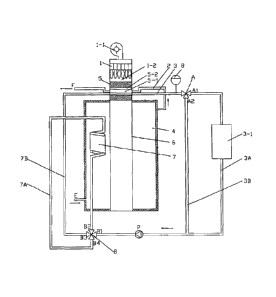
The gas hot water heating device of this embodiment is shown as
Figure 1, 2 and 3, including combustion device 1, inlet E and outlet G
of hot water pipeline 2, inlet I and outlet H of heating loop 3 as well as
water tank 4, and the first heat exchanger 5, the second heat
exchanger 6 and the third heat exchanger 7. Flue gas outlet 1-2 of
6
CA 02851548 2014-04-09
English Translation of PCT/CN2012/081653
combustion device 1 is connected in series to the flue gas path of the
first heat exchanger 5 and the second heat exchanger 6 according to
sequence. Inner pipe channel 5-1 served as the first flow channel and
outer pipe channel 5-2 wrapping the inner pipe channel served as the
second flow channel are provided in the first heat exchanger 5. Inner
and outer pipe channel are respectively connected to hot water
pipeline 2 and heating loop 3, which form the reverse channel
mutually, therefore water in hot water pipeline 2 will have heat
exchange with water flowing through heating loop 3 in the first heat
exchanger 5. Water tank 4 and the first flow channel 5-1 of the first
heat exchanger 5 are connected in series between inlet E and outlet
G of hot water pipeline 2, and the second flow channel 5-2 of the first
heat exchanger 5 and flow channel of the third heat exchanger 7 are
connected in series between inlet I and outlet H of heating loop 3.
Heat exchange can be done between the second heat exchanger 6 &
the third heat exchanger 7 and the water in water tank 4, which not
only is in water tank 4, but also is closely adjacent to it. Inlet E of hot
water pipeline 2 is water inlet of water tank 4 and it is connected to
water source. Outlet G of hot water pipeline 2 is connected to the
water end. Circulation branch 3B is provided between inlet I and outlet
H of heating loop 3, which forms a circulation loop together with the
second flow channel 5-2 of the first heat exchanger 5 and the flow
channel of the third heat exchanger 7. ON/OFF control valve Al is
equipped in the circulation branch.
It is more easily to understand the working principle and beneficial
effects in embodiment 2, then no more details will be provided. Please
refer to the related descriptions in Embodiment 2.
7
CA 02851548 2014-04-09
English Translation of PCT/CN2012/081653
Embodiment 2
The gas hot water heating system of this embodiment is shown as
Figure 4, including combustion device 1, hot water pipeline 2, heating
loop 3, water tank 4 and the first heat exchanger 5, the second heat
exchanger 6 and the third heat exchanger 7 (direct impact heat
exchanger). Fan 1-1 is equipped on the top of combustion device 1,
and flue gas outlet 1-2 of the lower combustion chamber is connected
in series to flue gas path of the first heat exchanger 5 and the second
heat exchanger 6. Water source E of hot water pipeline 2 is
connected to water inlet of water tank 4, and water outlet of water tank
4 is connected to the water end F of hot water pipeline after the first
heat exchanger 5. The heating loop 3 is connected in series with the
flow channels of the first heat exchanger 5 and the third heat
exchanger 7. The second heat exchanger 6 and the third heat
exchanger 7 are both located inside water tank 4, therefore they can
have heat exchange with the water inside water tank 4.
The first heat exchanger 5 practically is double-tube heat exchanger,
provided with inner pipe channel 5-1 and outer pipe channel 5-2
wrapping the inner pipe flow channel. Hot water pipeline 2 flows
through inner pipe channel 5-1 and heating loop 3 flows through outer
pipe channel 5-2, then heat exchange can be realized in the first heat
exchanger 5 between water in hot water pipeline 2 and that in heating
loop 3. And inner pipe channel 5-1 and outer pipe channel 5-2 are
reverse channels. In this embodiment, the first heat exchanger also
can be divided into two single-channel heat exchange tubes, and hot
water pipeline and heating loop separately pass through them. During
the practical manufacturing, it is obvious that the first heat exchanger
8
CA 02851548 2014-04-09
English Translation of PCT/CN2012/081653
can be designed as multi-channel heat exchange pipeline. Figure 8 is
expansion water tank.
In service, hot water pipeline 2 providing domestic water is an open
system, water process is shown as source of tap water-) water tank
4 the first heat exchanger (inner pipe channel) 4 user terminal
(shower head, etc). Heating loop 3 providing heating water is a closed
system, water process is shown as heating equipment at user
terminal (radiation fins, etc) 4 circulation water pump P 4 the third
heat exchanger 4 the first heat exchanger (outer pipe channel) 4
heating equipment at user terminal, expansion tank will be used as
pressure balance device in the loop; Flue gas process is shown as
combustion device 4 flue gas path of the first heat exchanger 4 flue
gas path of the second heat exchanger 4 flue gas exhaust. Hot water
pipeline exchanges heat with the second heat exchanger in water
tank, also executes rapid heat exchange via the first heat exchanger,
to supply large amount of hot water for user; heating loop absorbs the
heat saved in water tank through the third heat exchanger to preheat
the water in heating loop, then directly heat via the first heat
exchanger, making full use of the heat for heating. High temperature
flue gas produced by the combustion device firstly exchanges large
amount of heat through the first heat exchanger, then makes heat
exchange via the second heat exchanger. Also it can absorb the
potential moisture heat in flue gas, to greatly improve the thermal
efficiency of system.
Heating loop 3 includes heating branch 3A passing through heating
equipment 3-1 and heating branch 3A as well as circulation branch 3B
connecting the first heat exchanger 5 and the third heat exchanger 7,
9
= CA 02851548 2014-04-09
English Translation of PCT/CN2012/081653
which are controlled by valve. Heating branch 3A and circulation
branch 3B are connected in parallel. Heating loop 3 is of a control
valve A to switch circulation branch 3B and heating branch 3A. In
particular, two-position three-way valve A is provided at the junction of
circulation branch and heating branch in heating loop 3, to switch the
two branches by means of two switching positions Al and A2 of valve
A. Additionally, heating loop 3 also is equipped with the switching
device to change flow direction inside the third heat exchanger 7. In
terms of details, the switching device is four-way valve B with four
ports such as B1, 62, B3 and B4. Both ends of the third heat
exchanger 7 are connected to B2 and B4 respectively, while those of
the heating loop are connected to B1 and B3 respectively, therefore
top-in-bottom-out or bottom-in-top-out of the third heat exchanger 7
can be realized through status connection of 131-64 and B2-B3 or
B1-62 and B3-B4 of control valve. It is evident that this switching
device also can be applied in Embodiment 1.
When the heating loop works during service, Al position of valve A
opens, A2 position closes, B1-62 and B3-64 of valve B are connected,
and cold water from the heating equipment of user terminal enters the
third heat exchanger for heat absorption from bottom to top via 51-B2,
then enters the first heat exchanger for heat exchange via B3-64,
finally enters the heating equipment at users terminal for heating
through Al position of valve A. Because the first heat exchanger is
able to absorb the heat releasing from the second heat exchanger to
water tank, to avoid heat accumulation, too high water temperature
and pressure inside the water tank when heating is applied only, so as
to eliminate the potential safety hazards. When the heating branch
CA 02851548 2014-04-09
English Translation of PCT/CN2012/081653
stops and circulation branch is working, Al position of the valve
closes, while A2 position opens, and Bl-B4 and B2-B3 of valve B is
connected. Under the circumstances, high temperature heating hot
water from the first heat exchanger enters circulation branch 3B
through A2 position of valve A, then enters the third heat exchanger
from top to bottom via Bl-B4 to release heat for the cold water in
water tank. Finally enters the first heat exchanger again for heat
exchange via B2-63. Too high water temperature of the heating loop
in the first heat exchanger can be effectively avoided by means of
transferring the heat absorbed by heating loop in the first heat
exchanger to water tank via the third heat exchanger. At the same
time, heating speed can be rapidly improved by preheating the cold
water inside water tank, which is very beneficial to the users with large
capacity of domestic water.
Embodiment 3
The gas hot water heating system in this embodiment is shown as
Figure 5, its basic structure is the same as that of Embodiment 1, with
a difference in the simplified pipeline on both sides of the third heat
exchanger, therefore it can't switch the flow direction of the third heat
exchanger, with poor heat exchange efficiency.
Embodiment 4
The gas hot water heating system in this embodiment is shown as
Figure 6, its basic structure is the same as that of Embodiment 1, with
a difference in that heating branch is connected to auxiliary heating
branch in parallel. This auxiliary heating branch forms a heating
circulation loop together with the said third heat exchanger. For this
embodiment, the auxiliary heating branch is equipped with solar
11
CA 02851548 2014-04-09
English Translation of P C T/CN2 0 1 2/0 8 1 65 3
collector served as auxiliary heating device (also the auxiliary heating
device of other energy can be set as required). Therefore the heat of
solar collector can be transferred to the water tank via the third heat
exchanger in combination with the green energy system, so as to
reduce energy consumption of the system further.
Besides the above embodiments, other manners can be executed for
this invention. The technical schemes formed on the basis of
equivalent replacement or transformation will be within the protection
scope required by this invention.
12