Sélection de la langue

Search

Sommaire du brevet 2857577 

Énoncé de désistement de responsabilité concernant l'information provenant de tiers

Une partie des informations de ce site Web a été fournie par des sources externes. Le gouvernement du Canada n'assume aucune responsabilité concernant la précision, l'actualité ou la fiabilité des informations fournies par les sources externes. Les utilisateurs qui désirent employer cette information devraient consulter directement la source des informations. Le contenu fourni par les sources externes n'est pas assujetti aux exigences sur les langues officielles, la protection des renseignements personnels et l'accessibilité.

Disponibilité de l'Abrégé et des Revendications

L'apparition de différences dans le texte et l'image des Revendications et de l'Abrégé dépend du moment auquel le document est publié. Les textes des Revendications et de l'Abrégé sont affichés :

  • lorsque la demande peut être examinée par le public;
  • lorsque le brevet est émis (délivrance).
(12) Brevet: (11) CA 2857577
(54) Titre français: MAT DE PURGE DE COMPARTIMENT D'UN AERONEF SOUMIS A UNE PRESSION NEGATIVE
(54) Titre anglais: DRAINAGE MAST OF THE COMPARTMENT OF AN AIRCRAFT SUBJECTED TO A NEGATIVE PRESSURE
Statut: Octroyé
Données bibliographiques
(51) Classification internationale des brevets (CIB):
  • B64D 33/00 (2006.01)
  • B64C 1/00 (2006.01)
  • B64C 7/00 (2006.01)
  • B64D 1/16 (2006.01)
  • F04F 5/00 (2006.01)
(72) Inventeurs :
  • CASADO MONTERO, CARLOS (Espagne)
  • HERNANZ MANRIQUE, JOSE ANGEL (Espagne)
  • GRANA OTERO, JOSE (Espagne)
  • PARRA FABIAN, IGNACIO ESTEBAN (Espagne)
  • GALLEGO LORENZO, MIGUEL ANGEL (Espagne)
(73) Titulaires :
  • AIRBUS OPERATIONS S.L. (Espagne)
(71) Demandeurs :
  • AIRBUS OPERATIONS S.L. (Espagne)
(74) Agent: BERESKIN & PARR LLP/S.E.N.C.R.L.,S.R.L.
(74) Co-agent:
(45) Délivré: 2021-08-03
(22) Date de dépôt: 2014-07-21
(41) Mise à la disponibilité du public: 2015-01-22
Requête d'examen: 2019-07-15
Licence disponible: S.O.
(25) Langue des documents déposés: Anglais

Traité de coopération en matière de brevets (PCT): Non

(30) Données de priorité de la demande:
Numéro de la demande Pays / territoire Date
13382293.2 Office Européen des Brevets (OEB) 2013-07-22

Abrégés

Abrégé français

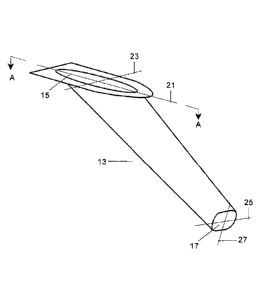
Un mât de drainage (13) configuré avec une section transversale ayant une zone diminuant à partir de sa section dentrée (15) qui doit être fixée dans la zone inférieure du compartiment (11) à sa section de sortie est décrit. La section dentrée et la section de sortie ont chacune deux axes de symétrie perpendiculaires (21, 23, 25, 27) de différentes longueurs. La section de sortie (17) est disposée dans un plan formant un angle (.beta.) entre 60 degrés et 120 degrés avec le plan de la section dentrée, améliorant lamorçage du mât de drainage, car lécoulement dair y contribue positivement en ayant la section de sortie dans cette position. Le mât est caractérisé en ce que le rapport entre laxe le plus court (27) et laxe le plus long (25) de la section de sortie se situe entre 0,2 et 0,6, laxe le plus long de la section de sortie étant parallèle au plan de la section dentrée et sa projection sur ledit plan étant perpendicualire à laxe plus long (21) de la section dentrée pour amorcer le mât de drainage fonctionnellement.


Abrégé anglais


A drainage mast (13) configured with a cross section having a decreasing area
from its entry
section (15) to be attached in the bottom zone of the compartment (11) to its
outlet section. The
entry section and outlet section each has two perpendicular axes of symmetry
(21, 23, 25, 27)
of different length.
The outlet section (17) is disposed in a plane forming an angle (.beta.)
between 60° and 120° with
the plane of the entry section, improving the drainage mast priming because
the airflow
contributes positively to it having the outlet section in that position.
The mast is characterized in that the ratio between the shorter axis (27) and
the longer axis (25)
of the outlet section is between 0.2 and 0.6, the longer axis of the outlet
section being parallel to
the plane of the entry section and its projection onto said plane being
perpendicular to the
longer axis (21) of the entry section to have the draining mast operatively
primed.

Revendications

Note : Les revendications sont présentées dans la langue officielle dans laquelle elles ont été soumises.


7
Claims
1. A drainage mast (13) to drain fluids from a compartment (11) of an
aircraft into
the atmosphere by gravity even when the pressure in the compartment (11) is
below
atmospheric pressure, the drainage mast (13) being configured with a cross
section
having a decreasing area from its entry section (15) arranged to be attached
in the
bottom zone of the compartment (11) to its outlet section (17), the
longitudinal axis of
the drainage mast (13) being disposed at an acute angle a with respect to the
plane
of the entry section (15) in the airflow direction, wherein:
the entry section (15) and outlet section (17) each have two perpendicular
axes
of symmetry (21, 23, 25, 27) of different length;
the entry section (15) is configured to be arranged with its longer axis of
symmetry (21) substantially parallel to the airflow direction;
the drainage mast (13) is configured to be arranged such that it has a
symmetrical configuration with respect to a plane substantially perpendicular
to the
fuselage envelope, passing through the longer axis of symmetry (21) of the
entry
section (15); and
the outlet section (17) is disposed in a plane forming an angle p between 600
and 120 with the plane of the entry section (15), characterized in that the
ratio
between the shorter axis (27) and the longer axis (25) of the outlet section
(17) is
between 0.2 and 0.6, the longer axis (25) of the outlet section (17) being
parallel to
the plane of the entry section (15) and its projection onto said plane being
perpendicular to the longer axis (21) of the entry section (15).
2. The drainage mast (13) of claim 1, wherein the angle p is between 70-85
.
3. The drainage mast (13) of claim 1 or 2, wherein the entry section
(15) has an
elliptical shape and the outlet section (17) has an elliptical, oval or dome-
ended
rectangular shape.
4282473
Date Recue/Date Received 2021-01-05

8
4.
An aircraft comprising a compartment (11) and the drainage mast (13) of any
one of claims 1-3.
4282473
Date Recue/Date Received 2021-01-05

Description

Note : Les descriptions sont présentées dans la langue officielle dans laquelle elles ont été soumises.


CA 02857577 2014-07-21
1
DRAINAGE MAST OF THE COMPARTMENT OF AN AIRCRAFT
SUBJECTED TO A NEGATIVE PRESSURE
FIELD OF THE INVENTION
The present invention relates to drainage masts of aircraft compartments
subjected to a negative pressure such as the compartment of the Auxiliary
Power
Unit or an engine nacelle.
BACKGROUND OF THE INVENTION
Known drainage systems of the Auxiliary Power Unit (APU) of an aircraft
comprise a mast for evacuating any liquid accumulated in the APU compartment
to the atmosphere by gravity.
One of the effects of the ventilation of the APU compartment typically
induced by a jet pump mechanism generated by the APU itself is a depression
(less pressure in the APU compartment than outside) generated in the APU
compartment.
Some of the drawbacks of a pressure impact in the drainage system are
mainly related to the difficulties in priming the drainage mast. That is, the
draining
capacity of the mast is sufficient once it is working fully filled with
liquid, but if the
ingestion of air into the APU compartment starts before the mast is filled
with
liquid, because there is a lower pressure in the APU compartment than outside,

the stresses induced by the air flow impede the flow of liquid, and it may
well
happen that the mast never gets filled or primed. Rather, typically, air
entering
the APU compartment almost completely prevents any outflow of liquid until the

liquid height inside the APU compartment is enough to balance the suction in
the
APU compartment, rendering the mast ineffective. Once this height is reached,
only a reduced cross section of the mast will be useful for draining and, in
addition, the liquid height in the APU compartment will be as large as what
would
be reached without a drainage mast.
US 5,996,938 proposes a drainage system comprising a drain tube which
is in fluid communication at its upper end with a liquid collecting floor and
at its

CA 02857577 2014-07-21
2
lower end to a check valve selectively open and placed as closely as possible
to
the aircraft overboard drain port. Liquids collected by the collecting floor
are
gravitationally directed into the drain tube upper end. The check valve is
configured to be open to fluid drainage from the tube out of the drain port
when
the pressure head of fluid upstream of the check valve exceeds fluid pressure
at
the drain port due to aircraft operating conditions. This drainage system is
therefore dependent of the said check-valve.
SUMMARY OF THE INVENTION
An object of the present invention is to provide a drainage mast able to
drain effectively the liquid contained in the compartment of an aircraft when
the
pressure within the compartment is lesser than the outside pressure and also
when the opposite happens without using any pressure control active device and
without causing any significant perturbation to the aerodynamic behavior of
the
aircraft.
To fulfill this object, the drainage mast of the invention has the following
features:
- Is configured with a cross section area decreasing from its entry section
to the compartment to its outlet section and is disposed at an acute angle a
relative to the compartment in the airflow direction. This favors priming the
mast
when the pressure inside the compartment is below atmospheric pressure.
- Their entry and outlet sections have two perpendicular symmetry axes of
different length, the entry section is arranged with its longer axis of
symmetry
substantially parallel to the airflow direction and the drainage mast has a
symmetrical configuration with respect to a plane substantially perpendicular
to
the fuselage envelope passing through the longer axis of symmetry of the entry

section. This configuration minimizes the drag of the drainage mast.
- The ratio between the shorter axis and the longer axis of the outlet
section is between 0.2 and 0.6. This feature is essential to have the draining
mast operatively primed.

CA 02857577 2014-07-21
3
In an embodiment, the outlet section is arranged in a plane forming an
angle p between 60-120 (preferably 70-85 ) with the plane of the entry
section,
being its longer axis parallel to the plane of the entry section and
perpendicular
to its longer axis in a projection over said plane. This feature improves the
drainage mast priming because the airflow contributes positively to it having
the
outlet section in that position.
Another important feature of the invention is that provides a ratio between
the areas of the outlet section and the entry section which optimizes the
fluid
drainage. That ratio is the one in which the value of the flow rate Qreq
required to
evacuate a predetermined volume of liquid in the compartment and the value of
flow rate Qprim evacuated by the drainage mast, when is fully primed, match
Other desirable features and advantages of the invention will become
apparent from the subsequent detailed description of the invention and the
appended claims, in relation with the enclosed drawings.
BRIEF DESCRIPTION OF THE DRAWINGS
Figure 1 is a schematic side view of a known drainage system of an APU
compartment of an aircraft.
Figure 2 is a schematic perspective view of the drainage mast of the
invention.
Figure 3 is a cross sectional view along the plane of symmetry of the
drainage mast of Figure 2.
Figure 4 is a diagram showing the variation of the flow rates Qprim and Qreq
as a function of the ratio R between the outlet and entry sections of the
drainage
mast.
DETAILED DESCRIPTION OF THE INVENTION
Figure 1 illustrates a drainage mast 13 of a compartment 11 of an aircraft
where liquids are accumulated with an entry section 15 connected to a bottom

CA 02857577 2014-07-21
4
zone of the compartment 11 and with an outlet section 17 for discharging said
liquids to the atmosphere.
As shown in Figure 1, the drainage mast 13 is usually arranged at an
acute angle a with respect to the compartment 11 in the airflow direction
(arrow
F).
The length L of the drainage mast 13 and the inclination angle a with
respect to the plane of the entry section 15 controls the effective height
Heft of the
liquid in the compartment 11 according to the equation:
Pout-Pin
pg Heff = pg (Ho + Lsin(a))=
where:
p: liquid density at ambient conditions;
g: gravity acceleration;
Heff: liquid height in the compartment 11 measured from the outlet section
17 of the drainage mast 13;
Pout: pressure outside of the compartment 11 (atmospheric pressure);
Pio: pressure inside of the compartment 11.
On the other hand, Ho is the liquid height in the compartment 11
measured from the entry section 15 of the drainage mast 13.
As already stated in the background of the invention if Pin< Pout may occur
the situation shown in Fig.1 in which the mast 13 is not completely primed
because Ho is not enough to compensate for the pressure difference between
Pin and Pot.
To achieve effective drainage of the compartment 11 when the pressure
inside Pin is lesser than the pressure outside Pout, the present invention
proposes
to configure the drainage mast with sections of a decreasing area from the
entry
section 15 toward the outlet section 17, the configuration complying with
certain
geometric conditions.
The progressive decrease in the area of the cross section of the drainage
mast 13 favors its priming because the flow rate supported upstream of a
particular intermediate section is larger than it can accommodate favoring the
accumulation of fluid upstream of said intermediate section and therefore its
priming. Thus air is prevented from entering the compartment 11 and the

CA 02857577 2014-07-21
problem posed by liquid splashing inside the compartment 11 is solved.
Complete priming of drainage mast 13 occurs when Heff is large enough to
compensate for the pressure difference between Pin and Pout.
In the embodiment shown in Figures 2 and 3 the entry section 15 has an
5 elliptical
shape with axes of symmetry 21, 23 (being axe 21 longer than axe 23),
the outlet section 17 has a dome-ended rectangular shape with symmetry axes
25, 27 (being axe 25 longer than axe 27) and the intermediate sections between

them which are configured so that the outer surface of drainage mast 13 is as
smooth as possible.
The ratio between the shorter symmetry axis 27 and the longer symmetry
axis 25 of the outlet section 17 is between 0.2 and 0.6. The inventor has
found
that a drainage mast 13 having an outlet section 17 configured within this
range
provides good priming results. Said ratio is applicable to any geometrical
shape
of the outlet section 17 and particularly to elliptical, oval and dome-ended
rectangular shapes. Drainage mast 13 is symmetrical about a plane A-A
substantially perpendicular to the fuselage envelope passing through the
longer
symmetry axis 21 of the entry section 15 and the outlet section 17 is disposed
in
a plane forming an angle ri between 60-120 (preferably between 70-85 ) with
the plane of the entry section 15.
An important aspect of the present invention is the ratio R between the
area of the outlet section 17 and the area of entry section 15.
The flow rate Qreq that is necessary to evacuate a given volume of liquid
by the outlet section 17 of the drainage mast 13 is given by the following
formula:
2
= __________________ ' AF)
1 + CLO;S
4 .)
where AP = (Pi a ¨ Picatt)I(+ (H0 + H1 being H1= Lsena
At area of outlet section 17
Con` coefficient of effective area of outlet section 17
CLOSS coefficient of losses in the drainage mast 13
Thus the flow rate Qreq does not depend from ratio R.
On the other hand, the discharge time is obtained in an iterative
calculation applying the formula T = Volume / Qreq and using 0.1 second

CA 02857577 2014-07-21
6
intervals. It is started with the volume of fluid accumulated in the
compartment 11
when the drainage mast 13 is primed. Qreq is a function of Ho + HI, therefore
to
find the new value of [10 for each iteration the liquid evacuated in the
previous
0.1 second interval is subtracted to the previous Volume. The iterative
process is
continued until Ho + fr1 = 0 and the total iteration time Ttot is the time
required for
the complete evacuation of the liquid.
The optimum value Ropt of ratio R is the one in which the value Qreq
matches the value of the function Qprim (see Figure 4) which sets the flow
rate
discharged through the outlet section 17 when the drainage mast 13 is primed
which is given by the following formula:
= r * g *
Qprrn + R2
where Pr is the primed coefficient of the oscillation of the liquid in the
drainage mast 13.
For ratios R smaller than Ropt, Ho and Ttot are greater that their optimum
values and the same happen for ratios R greater than Roo because the drainage
mast 13 is not primed.
The above calculations have been made assuming that the volume to
evacuate is known. If the drainage mast were subjected to different discharge
volumes, the ratio R would be established for that volume that would provide
the
best results for all of them.
Although the present invention has been described in connection with
various embodiments, it will be appreciated from the specification that
various
combinations of elements, variations or improvements therein may be made, and
are within the scope of the invention.

Dessin représentatif
Une figure unique qui représente un dessin illustrant l'invention.
États administratifs

Pour une meilleure compréhension de l'état de la demande ou brevet qui figure sur cette page, la rubrique Mise en garde , et les descriptions de Brevet , États administratifs , Taxes périodiques et Historique des paiements devraient être consultées.

États administratifs

Titre Date
Date de délivrance prévu 2021-08-03
(22) Dépôt 2014-07-21
(41) Mise à la disponibilité du public 2015-01-22
Requête d'examen 2019-07-15
(45) Délivré 2021-08-03

Historique d'abandonnement

Il n'y a pas d'historique d'abandonnement

Taxes périodiques

Dernier paiement au montant de 210,51 $ a été reçu le 2023-07-10


 Montants des taxes pour le maintien en état à venir

Description Date Montant
Prochain paiement si taxe générale 2024-07-22 347,00 $
Prochain paiement si taxe applicable aux petites entités 2024-07-22 125,00 $

Avis : Si le paiement en totalité n'a pas été reçu au plus tard à la date indiquée, une taxe supplémentaire peut être imposée, soit une des taxes suivantes :

  • taxe de rétablissement ;
  • taxe pour paiement en souffrance ; ou
  • taxe additionnelle pour le renversement d'une péremption réputée.

Les taxes sur les brevets sont ajustées au 1er janvier de chaque année. Les montants ci-dessus sont les montants actuels s'ils sont reçus au plus tard le 31 décembre de l'année en cours.
Veuillez vous référer à la page web des taxes sur les brevets de l'OPIC pour voir tous les montants actuels des taxes.

Historique des paiements

Type de taxes Anniversaire Échéance Montant payé Date payée
Le dépôt d'une demande de brevet 400,00 $ 2014-07-21
Taxe de maintien en état - Demande - nouvelle loi 2 2016-07-21 100,00 $ 2016-06-21
Enregistrement de documents 100,00 $ 2016-08-26
Taxe de maintien en état - Demande - nouvelle loi 3 2017-07-21 100,00 $ 2017-06-20
Taxe de maintien en état - Demande - nouvelle loi 4 2018-07-23 100,00 $ 2018-06-20
Taxe de maintien en état - Demande - nouvelle loi 5 2019-07-22 200,00 $ 2019-06-19
Requête d'examen 800,00 $ 2019-07-15
Taxe de maintien en état - Demande - nouvelle loi 6 2020-07-21 200,00 $ 2020-07-13
Taxe finale 2021-09-03 306,00 $ 2021-06-17
Taxe de maintien en état - Demande - nouvelle loi 7 2021-07-21 204,00 $ 2021-07-13
Taxe de maintien en état - brevet - nouvelle loi 8 2022-07-21 203,59 $ 2022-07-11
Taxe de maintien en état - brevet - nouvelle loi 9 2023-07-21 210,51 $ 2023-07-10
Titulaires au dossier

Les titulaires actuels et antérieures au dossier sont affichés en ordre alphabétique.

Titulaires actuels au dossier
AIRBUS OPERATIONS S.L.
Titulaires antérieures au dossier
S.O.
Les propriétaires antérieurs qui ne figurent pas dans la liste des « Propriétaires au dossier » apparaîtront dans d'autres documents au dossier.
Documents

Pour visionner les fichiers sélectionnés, entrer le code reCAPTCHA :


Pour visualiser une image, cliquer sur un lien dans la colonne description du document. Pour télécharger l'image (les images), cliquer l'une ou plusieurs cases à cocher dans la première colonne et ensuite cliquer sur le bouton "Télécharger sélection en format PDF (archive Zip)" ou le bouton "Télécharger sélection (en un fichier PDF fusionné)".

Liste des documents de brevet publiés et non publiés sur la BDBC .

Si vous avez des difficultés à accéder au contenu, veuillez communiquer avec le Centre de services à la clientèle au 1-866-997-1936, ou envoyer un courriel au Centre de service à la clientèle de l'OPIC.


Description du
Document 
Date
(yyyy-mm-dd) 
Nombre de pages   Taille de l'image (Ko) 
Demande d'examen 2020-09-11 4 195
Modification 2021-01-05 10 321
Abrégé 2021-01-05 1 18
Revendications 2021-01-05 2 48
Abrégé 2021-04-20 1 20
Taxe finale 2021-06-17 5 141
Dessins représentatifs 2021-07-12 1 5
Page couverture 2021-07-12 1 43
Certificat électronique d'octroi 2021-08-03 1 2 527
Abrégé 2014-07-21 1 22
Description 2014-07-21 6 240
Revendications 2014-07-21 2 49
Dessins 2014-07-21 2 19
Dessins représentatifs 2014-12-11 1 6
Page couverture 2014-12-30 2 47
Requête d'examen 2019-07-15 1 52
Cession 2014-07-21 5 126