Note : Les descriptions sont présentées dans la langue officielle dans laquelle elles ont été soumises.
CA 02858620 2014-08-06
SUPERCRITICAL TOTAL AIR TEMPERATURE SENSORS
BACKGROUND OF THE INVENTION
1. Field of the Invention
The present disclosure relates to temperature sensors, and more particularly
to total air
temperature sensors, such as used in aerospace applications.
2. Description of Related Art
Modern jet powered aircraft require very accurate measurement of outside air
temperature for inputs to the air data computer, engine thrust management
computer, and other
airborne systems. For these aircraft types, their associated flight
conditions, and the use of total
air temperature probes in general, air temperature is better defined by the
following four
temperatures: (1) Static air temperature (SAT) or (Ts), (2) total air
temperature (TAT) or (Tt), (3)
recovery temperature (Tr), and (4) measured temperature (Tm). Static air
temperature (SAT) or
(Ts) is the temperature of the undisturbed air through which the aircraft is
about to fly. Total air
temperature (TAT) or (Tt) is the maximum air temperature that can be attained
by 100%
conversion of the kinetic energy of the flow. The measurement of TAT is
derived from the
recovery temperature (Tr), which is the adiabatic value of local air
temperature on each portion
of the aircraft surface due to incomplete recovery of the kinetic energy.
Recovery temperature
(Tr) is obtained from the measured temperature (Tm), which is the actual
temperature as
measured, and which can differ from recovery temperature because of heat
transfer effects due to
imposed environments.
Total air temperature sensors used at the inlets of gas turbine engines, for
example, can
use airfoil shaped members with slots positioned so the gas stream to be
sensed passes through
one of the slots, and the temperature sensor element is mounted in the slot.
Examples of such
1
systems are disclosed in U.S. Patent No. 3,512,414, for example. Such sensor
designs can
mitigate the effects of high velocity foreign objects being ingested by the
engine, and can include
provisions for deicing.
One ongoing challenge for total air temperature measurements is associated
with
operation at higher Mach numbers. Compressibility effects occurring at higher
Mach numbers
can alter the desired flow pattern through traditional sensors, with potential
reduction in response
time, for example if there is reduced flow bathing the actual sensor element.
Such conventional methods and systems have generally been considered
satisfactory for
their intended purpose. However, there is still a need in the art for systems
and methods that
allow for improved total air temperature sensor performance, including
improved time response
and recovery error at elevated Mach numbers. There also remains a need in the
art for such
systems and methods that are easy to make and use. The present disclosure
provides a solution
for these problems.
2
Date Recue/Date Received 2021-01-13
CA 02858620 2014-08-06
SUMMARY OF THE INVENTION
A total air temperature sensor includes a supercritical airfoil body extending
from an
airfoil base to an opposed airfoil tip along a longitudinal axis. The
supercritical airfoil body
defines an interior flow passage with an inlet for fluid communication of
fluid into the interior
flow passage and an outlet for exhausting fluid out from the interior flow
passage. A
temperature probe is mounted within the interior flow passage for measuring
temperature of flow
through the interior flow passage to determine total air temperature. The
airfoil base can include
a mounting flange for mounting the supercritical airfoil body to a support
structure. It is
contemplated that the supercritical airfoil body can define a high pressure
surface and an
opposed low pressure surface each extending longitudinally from the airfoil
base to the airfoil tip,
wherein each of the high and low pressure surfaces extends downstream from a
leading edge to a
trailing edge of the supercritical airfoil body.
The inlet of the interior flow passage can be defined in the high pressure
surface, and the
outlet of the interior flow passage can be defined in the low pressure
surface. The inlet and
outlet of the interior flow passage can each define an elongate aperture
extending axially along a
respective exterior longitudinal surface of the supercritical airfoil body. It
is also contemplated
that the inlet of the interior flow passage can be defined axially in the
airfoil tip, and the outlet of
the interior flow passage can define a pair of elongate apertures each
extending axially along a
respective one of two opposing exterior longitudinal surfaces of the
supercritical airfoil body, for
example.
In certain embodiments, the supercritical airfoil body defines a supercritical
airfoil with a
characteristic normal shock location downstream of the inlet and outlet of the
interior flow
passage. The supercritical airfoil can extend from a leading edge to a
trailing edge that extends
3
CA 02858620 2014-08-06
downstream of the characteristic normal shock location. It is also
contemplated that the
supercritical airfoil can extend from a leading edge to a truncated trailing
edge that terminates
upstream of the characteristic normal shock location.
These and other features of the systems and methods of the subject disclosure
will
become more readily apparent to those skilled in the art from the following
detailed description
of the preferred embodiments taken in conjunction with the drawings.
4
CA 02858620 2014-08-06
BRIEF DESCRIPTION OF THE DRAWINGS
So that those skilled in the art to which the subject disclosure appertains
will readily
understand how to make and use the devices and methods of the subject
disclosure without
undue experimentation, preferred embodiments thereof will be described in
detail herein below
with reference to certain figures, wherein:
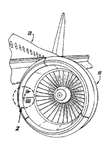
Fig. 1 is a perspective view of an exemplary embodiment of a total air
temperature sensor
constructed in accordance with the present disclosure, showing the sensor
mounted to the inlet of
a gas turbine engine;
Fig. 2 is a perspective view of the sensor of Fig. 1, showing the
supercritical airfoil with
inlet and outlet apertures of the interior flow passage defined in the high
and low pressure
surfaces, respectively;
Fig. 3 is a cross-sectional end elevation view of the sensor of Fig. 1,
schematically
showing flow into and out of the interior flow passage for total air
temperature measurements;
Fig. 4 is a perspective view of another exemplary embodiment of a total air
temperature
sensor constructed in accordance with the present disclosure, showing a
truncated trailing edge
that terminates upstream of the characteristic normal shock location;
Fig. 5 is a cross-sectional end elevation view of the sensor of Fig. 4,
schematically
showing flow into and out of the interior flow passage for total air
temperature measurements;
Fig. 6 is a perspective view of another exemplary embodiment of a total air
temperature
sensor constructed in accordance with the present disclosure, schematically
showing flow
entering the interior flow passage through an axially defined inlet in the
airfoil tip, and exiting
through a pair of elongate apertures;
5
CA 02858620 2014-08-06
Fig. 7 is a cross-sectional end elevation view of the sensor of Fig. 6,
schematically
showing flow into and out of the interior flow passage for total air
temperature measurements;
and
Fig. 8 is a perspective view of another exemplary embodiment of a total air
temperature
sensor constructed in accordance with the present disclosure, showing a
truncated supercritical
airfoil with an axially defined opening in the tip thereof.
6
CA 02858620 2014-08-06
DETAILED DESCRIPTION OF THE PREFERRED EMBODIMENTS
Reference will now be made to the drawings wherein like reference numerals
identify
similar structural features or aspects of the subject disclosure. For purposes
of explanation and
illustration, and not limitation, a partial view of an exemplary embodiment of
a total air
temperature sensor in accordance with the disclosure is shown in Fig. 1 and is
designated
generally by reference character 100. Other embodiments of total air
temperature probes or
sensors in accordance with the disclosure, or aspects thereof, are provided in
Figs. 2-8, as will be
described. The systems and methods described herein can be used to improve
total air
temperature sensor performance, for example at high Mach numbers.
As shown in Fig. 1, total air temperature sensor 100 can be mounted in the
inlet of a gas
turbine engine 10 on an aircraft 20, for example. Those skilled in the art
will readily appreciate
that this application is exemplary only, and that sensors in accordance with
this disclosure can be
used in any other suitable position on an aircraft or in any other suitable
application without
departing from the scope of this disclosure.
With reference now to Fig. 2, sensor 100 includes a supercritical airfoil body
102
extending from an airfoil base 104 to an opposed airfoil tip 106 along a
longitudinal axis A.
Airfoil base 104 includes a mounting flange for mounting airfoil body 102 to a
support structure
such as the engine inlet depicted in Fig. 1. As shown in Fig. 3, airfoil body
102 defines an
interior flow passage 108 with an inlet 110 for fluid communication of fluid
into interior flow
passage 108 and an outlet 112 for exhausting fluid out from interior flow
passage 108. A
temperature probe 114 is mounted within interior flow passage 108 for
measuring temperature of
flow through interior flow passage 108 to determine total air temperature in
the flow outside
sensor 100. Compressive effects on flow though interior flow passage 108 make
it possible for
7
CA 02858620 2014-08-06
temperature measurements by temperature probe 114 to be indicative of total
air temperature of
the airflow external to sensor 100.
With continued reference to Fig. 3, supercritical airfoil body 102 defines a
high pressure
surface 116 and an opposed low pressure surface 118 each extending
longitudinally from airfoil
base 104 to airfoil tip 106, which are shown in Fig. 2. Each of the high and
low pressure
surfaces 116 and 118 extends downstream from a leading edge 120 to a trailing
edge 122 of
airfoil body 102. Inlet 110 is defined in high pressure surface 116, and
outlet 112 is defined in
low pressure surface 118, to provide driving potential for the flow through
interior passage 108.
As shown in Fig. 2, inlet 110 and outlet 112 each define an elongate aperture
extending
axially along a respective exterior longitudinal surface of airfoil body 102,
i.e., high pressure
surface 116 and low pressure surface 118, respectively. Since airfoil body 102
forms a
supercritical airfoil, it delays formation of a shock, meaning it defines a
characteristic normal
shock location proximate trailing edge 122, as indicated schematically by the
shock lines in Fig.
3. Since this characteristic normal shock location is downstream of inlet 110
and outlet 112 flow
through interior flow passage 108 is not disrupted by external flows at Mach
numbers high
enough to form a normal shock. This structure allows sensor 100 to have
greater flow bathing
temperature probe 114 than in traditional configurations where a shock is
formed. Therefore, the
time response and recovery error of sensor 100 remains substantially
unaffected by the formation
of a normal shock as the external flow approaches higher Mach numbers, e.g.,
compared to
traditional sensors.
In Fig. 3, the supercritical airfoil extends from leading edge 120 to a
trailing edge 122
that extends downstream of the characteristic normal shock location. With
reference now to Fig.
4, total air temperature sensor 200 is similar to sensor 100 described above,
however the
8
CA 02858620 2014-08-06
supercritical airfoil of airfoil body 202 extends from a leading edge 220 to a
truncated trailing
edge 222. As shown in Fig. 5, trailing edge 222 terminates upstream of the
characteristic normal
shock location, which is indicated schematically by the shock line in Fig. 5,
to provide improved
time response and recovery error even at high Mach numbers, as described above
for sensor 100.
Aside from trailing edge 222 being truncated upstream of the normal shock
location, the airfoil
upstream of sensor 200 is identical to that in sensor 100, and the flow
through interior flow
passage 208 is similar to that described above for sensor 100, as indicated
schematically by the
flow arrows in Fig. 5. Those skilled in the art will readily appreciate that
truncated trailing edge
222 of sensor 200 allows for a wider element passage for a given chord length
and causes airfoil
body 202 to be lower in weight than airfoil body 102.
Referring now to Fig. 6, another exemplary embodiment is shown, namely total
air
temperature sensor 300. Sensor 300 is similar to sensor 100 described above,
however, the inlet
310 of the interior flow passage in sensor 300 is defined axially in the
airfoil tip of airfoil body
302. The outlet of the interior flow passage in sensor 300 is a pair of
elongate apertures 312 each
extending axially along a respective one of two opposing exterior longitudinal
surfaces of the
airfoil body 302. The large arrows in Fig. 6 schematically indicate the flow
into and out of the
interior flow passage. As indicated schematically by the flow arrows and shock
line in Fig. 7,
inlet 310 and outlet apertures 312 are all located upstream of the
characteristic normal shock
location of the supercritical airfoil, to provide the time response and
recovery error even at high
Mach numbers described above with respect to sensor 100. Fig. 8 shows another
exemplary
embodiment of a supercritical total air temperature sensor 400 that is similar
to sensor 300,
including the inlet and outlet configuration, but has a truncated trailing
edge 422 like sensor 200
described above. The normal shock location is not shown for sensor 400, but
see, e.g., the
9
CA 02858620 2014-08-06
normal shock location shown in Fig. 5. The configuration of sensor 400
provides improved time
response and recovery error at high Mach numbers relative to traditional
sensors, as described
above with respect to sensors 100, 200, and 300.
While sensors 100, 200, 300 and 400 are shown and described without a deicing
device,
those skilled in the art will readily appreciate that, a deicing device, such
as an electrical heater
or mechanical (e.g. pneumatic) device, could be added on or near the leading
edges to prevent
ice buildup.
In addition to providing improved time response and recovery error at high
Mach
numbers relative to traditional sensors, the systems and methods disclosed
herein can allow for
improved performance during icing conditions, are low drag, cause minimal wake
disturbance,
produce less aerodynamic induced noise, and provide a simple low cost design
relative to
traditional sensors. Those skilled in the art will readily appreciate that
with proper airfoil
selection, improved total air temperature sensor performance, including
improved time response
and recovery error can be obtained for angles of attack up to 10 . Those
skilled in the art will
also readily appreciate that the angle of incidence of the airfoil can be
adjusted as needed to
obtain the desired performance.
While shown and described in the exemplary context of air flow, those skilled
in the art
will readily appreciate that total air temperature measurements are exemplary
only. Similar
measurements can be made for any other suitable fluid using the techniques
described herein
without departing from the scope of this disclosure.
The methods and systems of the present disclosure, as described above and
shown in the
drawings, provide for total air temperature sensors with superior properties
including improved
time response at high Mach numbers relative to traditional sensors. While the
apparatus and
CA 02858620 2014-08-06
methods of the subject disclosure have been shown and described with reference
to preferred
embodiments, those skilled in the art will readily appreciate that changes
and/or modifications
may be made thereto without departing from the spirit and scope of the subject
disclosure.
11