Note : Les descriptions sont présentées dans la langue officielle dans laquelle elles ont été soumises.
CA 02860904 2014-07-10
WO 2013/104769 PCT/EP2013/050508
1
SEAL ASSEMBLY FOR NESTED DUAL DRILL PIPE
TECHNICAL FIELD
[0001] The disclosure relates generally to the field of drill pipe used in
drilling
wellbores through subsurface formations. More particularly, the disclosure
relates to
"dual" drill pipe, in which two separate fluid conduits are provided within a
single pipe
extending from a drilling unit into a wellbore, and to seals for maintaining
fluid tight
connections between inner fluid conduits within such dual drill pipe.
BACKGROUND
[0002] Dual drill pipe is disclosed, for example, in U.S. Patent No. 3,208,539
issued to
Henderson ("the Henderson '539 patent"). Generally, dual drill pipe includes
conventional, threadedly connected drill pipe, such as conforms to standards
set by the
American Petroleum Institute, Washington, D.C. An inner conduit or tube may be
disposed in the interior of the conventional drill pipe to provide an
additional fluid
conduit. As explained in the Henderson '539 patent, the additional fluid
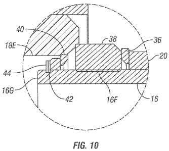
conduit may
be used to transport drill cuttings from a drill bit back to the surface
during drilling
operations. A possible advantage of using the additional conduit for such
purpose is
that the conduit has a smaller cross-sectional area than an annular space
between the
exterior of the conventional drill pipe and the wall of the wellbore. Such
smaller cross-
sectional area enables higher drilling fluid velocity, thus requiring less
drilling fluid
flow to entrain the drill cuttings and return them to the surface. Another
possible
advantage of using the additional conduit for cuttings return is in drilling
highly
inclined wellbores. In such wellbores, cuttings tend to settle on the bottom
of the
wellbore, sometimes leading to "packing", and haying the drill pipe become
stuck in the
wellbore as a result.
[0003] Dual drill pipe structures known in the art may require extended seal
engagement features for the inner tube to be sealingly engaged between
segments of
the dual drill pipe, and such seal engagement features may not accommodate
extensive
axial misalignment of the segments of drill pipe during assembly or
disassembly. There
exists a need for improved sealing devices for the inner pipe of a nested dual
drill pipe.
CA 02860904 2016-01-19
2
SUMMARY
[0003.1] According to a first aspect of the present invention, there is
provided a seal
assembly for a nested dual drill pipe, comprising:
a female seal assembly at one longitudinal end of a tube and a male seal
assembly at the other longitudinal end of the tube, the tube being nested
in a drill pipe segment having a tapered thread assembly guide at each
longitudinal end thereof;
wherein the female seal assembly includes a larger internal diameter portion
at
an open end thereof, a taper adjacent to the larger internal diameter
portion, and a smaller internal diameter portion adjacent to the taper;
wherein the male seal assembly includes a smaller external diameter portion
(16G) at an open end thereof, a seal area adjacent to the smaller external
diameter portion, and a larger external diameter portion adjacent to the
seal area, the seal area including a seal ring; and
wherein the larger internal diameter portion and the smaller external diameter
portion have diameters selected to prevent contact with each other during
assembly of two adjacent drill pipe segments at a maximum axial
misalignment allowed upon initial engagement of the tapered threads on
the assembly guides on adjacent drill pipe segments prior to the tapered
threads becoming fully engaged, and wherein the larger and smaller
internal diameter portions and the larger and smaller external diameter
portions have diameters selected to enable free longitudinal movement of
the male seal assembly into the female seal assembly while maintaining
the seal ring in the seal area fully energized.
[0003.2] According to another aspect of the present invention, there is
provided a seal
assembly for a single drill pipe, comprising:
CA 02860904 2016-01-19
2a
a female seal assembly at one longitudinal end ola drill pipe segment and a
male seal assembly at the other longitudinal end of the drill pipe segment,
each of the longitudinal ends of the drill pipe segment having a tapered
thread assembly guide;
wherein the female seal assembly includes a larger internal diameter portion
at
an open end thereof, a taper adjacent to the larger internal diameter
portion, and a smaller internal diameter portion adjacent to the taper;
wherein the male seal assembly includes a smaller external diameter portion at
an open end thereof, a seal area adjacent to the smaller external diameter
portion, and a larger external diameter portion adjacent to the seal area,
the seal area including a seal ring; and
wherein the larger internal diameter portion and the smaller external diameter
portion have diameters selected to prevent contact with each other during
assembly of two adjacent drill pipe segments at a maximum axial
misalignment allowed upon initial engagement of the tapered threads on
the assembly guides on adjacent drill pipe segments prior to the tapered
threads becoming fully engaged, and wherein the larger and smaller
internal diameter portions and the larger and smaller external diameter
portions have diameters selected to enable free longitudinal movement of
the male seal assembly into the female seal assembly while maintaining
the seal ring in the seal area fully energized.
[0004] The present disclosure describes a seal assembly for a nested dual
drill pipe, or a
single drill pipe, including a female seal assembly at one longitudinal end of
a chill pipe
and a male seal assembly at the other longitudinal end of the drill pipe. The
female seal
assembly includes a larger internal diameter portion at an open end thereof, a
taper
adjacent to the larger internal diameter portion, and a smaller internal
diameter
portion adjacent to the taper. The male seal assembly includes a smaller
external
CA 02860904 2016-01-19
2b
diameter portion at an open end thereof, a seal area adjacent to the smaller
external =
diameter portion, and a larger external diameter portion adjacent to the seal
area. The
larger internal diameter portion and the smaller external diameter portion
have
diameters selected to prevent contact with each other during assembly of two
adjacent
drill pipe segments at maximum axial displacement thereof. The larger and
smaller
internal diameter portions and the larger and smaller external diameter
portions have
diameters selected to enable free longitudinal movement of the male seal
assembly into
the female seal assembly while maintaining a seal ring in the seal area fully
energized.
[0005] In at least one embodiment, the seal area further includes an anti-
extrusion ring
on one side of the seal ring, the anti-extrusion seal ring having a diameter
selected to fit
within the smaller internal diameter portion.
[0006] In at least one embodiment, the seal area further includes an anti-
extrusion ring
on one side of the seal ring, the anti-extrusion seal ring having a diameter
selected to fit
within the larger internal diameter portion.
[0007] In at least one embodiment, the taper has an internal diameter equal to
the
internal diameter of the smaller internal diameter portion at a longitudinal
end
adjacent thereto and an internal diameter equal to the internal diameter of
the larger
internal diameter portion at a longitudinal end adjacent thereto.
[0008] In at least one embodiment, the female seal assembly has a minimum
internal
diameter portion longitudinally inwardly from and proximate the smaller
internal
diameter portion, the minimum internal diameter portion having an internal
diameter
smaller than an outside diameter of the smaller external diameter portion of
the male
seal assembly.
CA 02860904 2014-07-10
WO 2013/104769 PCT/EP2013/050508
3
[0009] In one aspect, the drill pipe member is an inner tube that can be
nested in a
drill pipe segment having a tapered assembly guide at each longitudinal end
thereof.
[0010] In at least one embodiment, the tapered assembly guide at each
longitudinal
end of the drill pipe segment includes a corresponding tapered threaded joint.
[0011] In another aspect, the drill pipe member is a drill pipe segment having
a
tapered assembly guide at each longitudinal end thereof.
[0012] In at least one embodiment, the tapered assembly guide on each
longitudinal
end of the drill pipe segment includes tapered threads.
[0013] In at least one embodiment, the drill pipe segment forms an outer pipe
of a
nested dual drill pipe segment.
[0014] In at least one embodiment, an inner tube nested in the drill pipe
segment that
forms the outer pipe of a nested dual drill pipe segment includes another
female seal
assembly at one longitudinal end thereof and another male seal assembly at the
other
longitudinal end thereof.
[0015] Other aspects and advantages will be apparent from the description and
claims
which follow.
BRIEF DESCRIPTION OF THE DRAWINGS
[0016] FIG. 1 shows an example of an assembled dual drill pipe segment
according to
the invention.
[0017] FIGS. 2A and 2B show, respectively, an end section and a side section
of an
example male (pin) end of conventional drill pipe modified to retain an inner
tube.
[0018] FIGS. 3A and 3B show, respectively, an end section and a side section
of an
example female (box) end of conventional drill pipe modified to retain an
inner tube.
[0019] FIGS. 4A and 4B, show, respectively, an end view and a side section of
a tube
retainer/sealing device disposed in the modified pin end (FIGS. 2A and 2B) of
the
conventional drill pipe.
[0020] FIG. 5 shows an example of a female end of an inner pipe seal assembly.
[0021] FIG. 6 shows a side view of a retaining ring disposed on the end of the
inner
tube engaged with the modified box end shown in FIGS. 3A and 3B.
CA 02860904 2014-07-10
WO 2013/104769 PCT/EP2013/050508
4
[0022] FIG. 7 shows an example female seal seat assembly disposed on the end
of the
inner tube.
[0023] FIG. 8 shows an example of a male end of an inner tube seal assembly.
[0024] FIG. 9 shows the inner seal assembly male and female sections partially
engaged.
[0025] FIG. 10 shows a detailed view of the seal portion of the sections shown
in FIG.
9.
[0026] FIGS. 11 and 12 show similar views as FIGS. 9 and 10, with the seal
portions
more closely engaged.
[0027] FIGS. 13 and 14 show views similar to FIGS. 11 and 12, respectively,
wherein
a seal assembly is used on a drill pipe.
DETAILED DESCRIPTION
[0028] An example of a dual drill pipe according to the various aspects of the
invention is shown in cut away view in FIG. 1. The dual drill pipe 11 may
include a
segment ("joint") 10 of "conventional" drill pipe, for example as made to
industry
standards set by the American Petroleum Institute, Washington, D.C. ("API")
Conventional drill pipe may be threadedly connected end to end using API
standard
threaded couplings called "tool joints" disposed at each longitudinal end of
the drill pipe
joint 10. The couplings are typically referred to as a "box" or female
threaded end,
shown at 12 in FIG. 1, which threadedly engages and makes a sealed connection
to a
"pin" or male threaded end in an adjacent pipe joint. The pin end is shown at
14 in
FIG. 1. The threads on the box end and the pin end may be tapered, and the
significance of such thread taper will be further explained below. It is also
within the
scope of the present disclosure that adjacent segments of drill pipe have pin
end and
box end tool joints that couple together other than using external threads on
the pin
end and internal threads on the box end. In such examples, a seal assembly as
explained herein may be used with any combination of tool joints on the outer
(drill)
pipe that are guided together using corresponding tapered features on the
respective
tool joints. For purposes of defining the scope of the present disclosure, the
foregoing
features, including tapered threads, may be referred to as "tapered guides."
For
CA 02860904 2014-07-10
WO 2013/104769 PCT/EP2013/050508
purposes of explaining the various examples herein, the term "axial
displacement" may
be used to describe the amount of offset between the longitudinal axis of each
of the two
segments of drill pipe being assembled.
[0029] An inner conduit or tube 16 may be disposed in the interior bore of the
pipe
joint 10. A tube retainer 18 may be affixed to one end of the inner tube 16.
The tube
retainer 18 may have an internal bore (explained further below) configured to
sealingly
engage the opposite end of the inner tube 16 wherein suitable sealing devices
may be
used to provide a pressure tight seal between adjacent segments of the inner
tube 16,
wherein such adjacent segment is included in an adjacent joint of the dual
drill pipe 11.
The opposite end of the inner tube 16 may include a device 20 to retain the
inner tube
16 longitudinally fixed in the interior of the pipe joint 10. The device 20
may include
passages 24 to enable fluid to be moved in an annular space 13 between the
outer wall
of the inner tube 16 and the inner wall of the pipe joint 10. A plurality of
standoffs 30
may be affixed to the exterior wall of the inner tube 16 at longitudinally
spaced apart
positions and at various circumferential orientations.
[0030] The inner tube 16 may be made from a material that has at least the
same
yield point as the material from which the pipe joint 10 is made.
[0031] An example structure for the pin end tool joint 14 is shown in end view
in FIG.
2A and in side cut away view in FIG. 2B. In FIG. 2B, the interior of the end
of the male
threaded coupling may include a retaining feature such as a generally
cylindrically
shaped receiving bore 15 ("pin end receiving bore") having a larger diameter
than the
nominal internal diameter of the pin end 14. The receiving bore 15 may extend
longitudinally for a selected length to terminate in an internal shoulder 17,
wherein the
pin end 14 may be maintained at its nominal internal diameter. The shoulder 17
provides a positive stop for the tube retainer (18 in FIG. 1) when the inner
tube (16 in
FIG. 1) is inserted into the pipe joint (10 in FIG. 1).
[0032] An example structure for the box end tool joint 12 is shown in end view
in FIG.
3A and in cut away side view in FIG. 3B. In FIG. 3B, the longitudinally
innermost
portion of the threaded coupling may include a retaining feature such as a
generally
cylindrically shaped receiving bore 19 ("box end receiving bore") having a
diameter
larger than the nominal internal diameter of the tool joint 12 and that
extends
CA 02860904 2014-07-10
WO 2013/104769 PCT/EP2013/050508
6
longitudinally into the tool joint for a selected length. The box end
receiving bore 19,
similar to the pin end receiving bore, terminates in a shoulder 21 where the
nominal
internal diameter of the tool joint 12 resumes. The shoulder 21 provides a
positive stop
for the retaining device (20 in FIG. 1).
[0033] FIGS. 4A and 4B show, respectively, an end view and a cut away side
view of
the pin end tube retainer 18 (also referred to herein as the "pin end inner
tube seal
assembly" later in the present description). FIG. 4B shows that the pin end
tube
retainer 18 may include a generally cylindrically shaped main body 18C with a
plurality of circumferentially spaced apart protrusions 18B. The protrusions
18B
subtend a diameter that may be approximately the same as the pin end receiving
bore
(15 in FIG. 2B). The protrusions 18B provide the pin end tube retainer 18 with
the
capability of being longitudinally stopped by the shoulder (17 in FIG. 2B)
while
enabling fluid flow through the annular space (13 in FIG. 1). The pin end tube
retainer
18 may be affixed to the inner tube 16 such as by welding. The pin end tube
retainer 18
may include a generally cylindrical inner bore 18A having a diameter selected
to
engage a seal assembly (FIG. 6) disposed on the opposed end of an adjacent
segment of
the inner tube. The pin end tube retainer 18 inner bore 18A may have a taper
in its
internal diameter for engaging anti-extrusion rings (FIG. 6) that hold a seal
in the seal
assembly, as will be further explained with reference to FIG. 5.
[0034] FIG. 5 shows a sectional view of the dual drill pipe joint 11, in
particular the
box end inner tube retaining device 20. In the present example the box end
inner tube
retainer (referred to later herein as the "male seal assembly") 20 may be
threadedly
coupled to a corresponding thread formed at a selected distance from the
longitudinal
end of the inner tube 16. The box end inner tube retainer 20 may thus be
threadedly
affixed to the inner tube 16. A snap ring or spiral locking ring 32 may be
used to hold
the box end retainer 20 in place on the inner tube 16.
[0035] Assembling the joint of dual drill pipe 11 may include the following
steps. The
inner tube 16 may have the pin end tube retainer 18 affixed to one
longitudinal end
thereof, such as, for example, by welding. The assembled inner tube 16, and
pin end
tube retainer 18 may be inserted into the pipe joint (10 in FIG. 1) through
the pin end
tool joint (12 in FIG. 1) until the pin end retaining device 18 stops on the
pin end
CA 02860904 2016-01-19
7
shoulder (17 in FIG. 2B). The length of the inner tube 16 in the present
example may
be selected so that when no longitudinal stress is applied to the inner tube
16 the
threads 33A for the box end retainer 20 would be at a longitudinal position
inside the
tool joint beyond the box end shoulder (21 in FIG. 3B). Longitudinal tension
may be
applied to the inner pipe 16 so that the threads 33A for the box end retainer
20 become
accessible. The box end retainer 20 may then be threaded 33B onto the exterior
of the
inner tube 16, and the locking ring 32 affixed to the inner tube 16. The
longitudinal end
of the box end retainer 20 may include an internal bevel, groove or recess 32A
on its
internal diameter that covers the locking ring 32 by unthreading the box end
retainer
20 from the inner tube 16 until unthreading is stopped by the locking ring 32.
Such
configuration may provide increased reliability by preventing the locking ring
32 from
disengaging from the inner tube 16. Tension may then be released from the
inner tube
16 so that the box end retainer 20 rests on the box end shoulder (21 in FIG
3B). Thus,
the inner tube 16 may be retained in the pipe joint 10 so that the
longitudinal ends of
the inner pipe 16 are in substantially fixed relation with the longitudinal
ends of the
pipe joint 10. The height and configuration of one or more standoffs (30 in
FIG. 1)
cooperate with the tension retained in the inner tube 16 to provide stable
bending of the
inner tube 16 as the pipe joint 10 is bent during ordinary drilling operations
and
substantially prevents buckling of the inner tube 16. Tension may be retained
in the
inner tube 16 after the foregoing assembly procedure by suitable selection of
the
unstressed length of the inner tube 16.
[0036] After completion of the foregoing assembly procedure, and referring
to
FIG. 6, a first example of a seal assembly may be affixed to the end of the
inner pipe 16
extending longitudinally outward (with reference to the box end) beyond the
box end
retainer 20. The seal assembly may include a connector spacer 34 placed in
contact
with the box end retainer 20 by sliding longitudinally along the inner tube
16. Next a
first anti-extrusion ring 36 may be applied to the end of the inner tube 16. A
seal 38,
which may be made from elastomer and shaped substantially as an annular ring,
may
be disposed on the inner tube 16 end. The seal 38 may be followed by a second
anti-
extrusion ring 40. The second anti-extrusion ring 40 may have a smaller
diameter than
the first anti-extrusion ring 36 to cooperatively engage with the tapered
inner surface
(18A in FIG. 4B) of the pin end retainer (18 in FIG. 4B), as will be further
described
CA 02860904 2014-07-10
WO 2013/104769 PCT/EP2013/050508
8
with reference to FIG. 8. The second anti-extrusion ring 40 may be followed by
a spacer
shim 42 as needed and a spiral or other type of locking ring 44 to hold the
entire seal
assembly as described longitudinally on the end of the inner tube 16.
[0037] When a joint of dual drill pipe configured and assembled as explained
above is
threadedly coupled to an adjacent joint of the dual drill pipe, the seal
assembly shown
in FIG. 6 sealingly engages the interior surface of the pin end retainer 18 in
the
adjacent dual drill pipe joint. The box and pin end threads may be designed
for metal
to metal seal, or a separate sealing device may be used to cause the pipe
joints 10 to
sealingly engage each other when threaded together. As previously explained
herein,
the threads on the respective tool joints (12, 14 in FIG. 1) may be tapered.
The shape,
taper and respective internal diameters of the inner surface of the pin end
retainer (see
FIG. 4B) may enable assembly of one pipe joint to the next using conventional
drill pipe
assembly techniques, in which the threads on the mating tool joints provide
for a
selected amount of axial misalignment during initial threading of the pin end
to the box
end.
[0038] It will be appreciated by those skilled in the art that the example
arrangement
of a dual drill pipe, in which the inner tube is ordinarily in tension may be
reconfigured
so that the inner tube 16 is ordinarily in longitudinal compression. For
example, the
shoulder in either the pin end tool joint (14 in FIG. 1) or the box end tool
joint (12 in
FIG. 1) may be machined to stop the corresponding retainer from exiting the
respective
tool joint longitudinally, rather than stopping the corresponding retainer
from entering
the respective tool joint further. The opposed tool joint may have a suitable
groove
machined therein for a retaining ring such as a spiral locking ring or snap
ring so that
when the inner tube 16 is inserted into the pipe joint 10, after the
respective retaining
device stops on the corresponding shoulder, the inner pipe is compressed to
enable
insertion of the retaining ring. The uncompressed length of the inner pipe 16
may be
selected so that when uncompressed, the snap ring groove is not accessible to
retain the
respective retaining device in the pipe joint 10.
[0039] Example inner tube seal assembly components will now be explained in
more
detail with reference to FIGS. 7-12.
CA 02860904 2016-01-19
9
[0040] FIG. 7 shows an example of a pin end inner tube retainer 18, which as
stated
above may also perform the function of the pin end inner tube seal assembly.
The pin
end inner tube retainer 18 (hereinafter referred to as the female inner tube
seal
assembly) may include a shoulder 18B that cooperatively engages the shoulder
(15 in
FIG. 2B) formed in the pin end tool joint connection (14 in FIG. 2B). An
internal
opening on one end of the female inner tube seal assembly 18, shown at 18C,
may have
an internal diameter selected to receive one end of the inner tube (16 in FIG.
1). The
female inner tube seal assembly 18 may be welded to the end of the inner tube
(16 in
FIG. 1) or may be affixed, for example, using a retaining ring 18D1 and
internal seal
18D. An internal bore at the open end of the female inner tube seal assembly
18, for
receiving the opposed end of an adjacent segment of the inner tube (16 in FIG.
1), may
include a larger diameter segment 18E having an internal diameter selected to
engage
a seal ring (explained with reference to FIG. 8). The larger diameter segment
18E may
be adjacent, through a suitable taper or beveled portion 18E1 to a smaller
diameter
portion 18F. The smaller diameter portion 18F may engage a corresponding
portion of
the box end of the inner tube seal assembly (explained with reference to FIG.
8). The
smaller diameter portion 18F may be further tapered at its opposite
longitudinal end,
at 18F1, to a minimum internal diameter portion 18G, which may form a positive
stop
for longitudinal motion of the box end (FIG. 8) inner tube seal assembly into
the pin end
of the inner tube seal assembly 18.
[0041] A box end of the inner tube seal assembly is shown at 16A in FIG. 8.
The
present example of the box end inner tube seal assembly 16A, referred to
hereinafter as
the "male seal assembly"), may be formed directly into the longitudinal end of
the inner
tube extending beyond the inner tube retainer 20. The inner tube retainer 20
may be
threadedly engaged with an outer surface of the inner tube 16. The opposite
longitudinal end of the male inner tube seal assembly 16A may include a larger
outer
diameter portion 16E adjacent to a seal area or groove 16F in which may
include an
elastomer or similar seal ring 38. A smaller outer diameter portion of the
opposite
longitudinal end, shown at 16G, may be adjacent to the other end of the seal
groove
16E. The seal groove 16F may include, as explained with reference to FIG. 6, a
lock
CA 02860904 2014-07-10
WO 2013/104769 PCT/EP2013/050508
ring 44, spacer shim 42, front anti-extrusion ring 40, the seal 38, and a rear
anti-
extrusion ring 36 as explained with reference to FIG. 6.
[0042] Because the inner tube (16 in FIG. 1) is held in fixed longitudinal
relationship
with the drill pipe segment (11 in FIG. 1), as the pin end and box end thereof
are
threadedly engaged as explained above, the female inner tube seal assembly 16A
will
be drawn into engagement longitudinally with the male inner tube seal assembly
(18 in
FIG. 7). Referring to FIG. 9, the two components of the inner tube seal
assembly are
shown being drawn together. The drill pipe box end and pin end are omitted
from FIG.
9 for clarity of the illustration. The relevant portions of the male and
female inner tube
seal assemblies 16A, 18 are shown in detail in FIG. 10. The smaller diameter
portion
16G of the male inner tube seal assembly may be longitudinally disposed within
the
larger diameter portion 18E of the female seal assembly 18 during engagement.
The
relative diameters of the foregoing components may be selected to enable a
selected
amount of axial misalignment (e.g., lateral displacement of the axes of the
adjacent drill
pipe segments during threaded engagement) without causing contact between the
respective tube seal assembly components at the maximum axial displacement
possible
using tapered threads on the respective tool joints (12, 14 in FIG. 1). FIGS.
9 and 10
show the seal assemblies when the two segments of drill pipe are at their
maximum
displacement transverse to the respective longitudinal axis of each drill pipe
segment.
[0043] In FIG. 11, the male inner tube seal assembly 16A and the female 18
thereof
are shown wherein the two drill pipe segments are fully threadedly engaged.
Detail of
the same components shown in FIG. 10 are shown in FIG. 12 as fully engaged
longitudinally. The smaller diameter portion 16G of the male seal assembly can
be
observed in close proximity to the smaller diameter portion 18F of the female
seal
assembly. The respective smaller diameter portions 16G, 18F may have external
and
internal diameters selected, respectively, to enable free longitudinal
movement of the
smaller diameter portions 16G, 18F past each other, while causing the seal
ring 38 to
remain fully energized.
[0044] A nested dual drill pipe having an internal tube seal assembly
according to the
present example may have one or more of the following advantages. The dual
drill pipe
may be assembled substantially identically to conventional drill pipe. The
inner tube
CA 02860904 2016-01-19
11
does not require extended length or specially configured seal surfaces because
the ends
of the inner tube may be in longitudinally fixed relationship with respect to
the
longitudinal ends of the pipe joint. The inner tube may be less susceptible to
buckling
or damage because of the helical shaped imposed thereon by the standoff
configuration
and a seal element may be less susceptible to extrusion while providing for
simple
assembly and providing for axial misalignment of adjacent drill pipe segments
during
threaded assembly and disassembly.
[0045] In another example, the seal assembly used on an inner pipe of a nested
dual drill pipe
may be used on the outer pipe, or on a conventional single drill pipe. FIG. 13
shows a pin end
tool joint 114 of one segment of a drill pipe (similar to that shown in FIG.
1) coupled to a box
end tool joint 112 of an adjacent segment of drill pipe. The tool joints 112,
114 may be coupled
by respective tapered threads 112A, 114A. The threads 112A, 114-A may be any
type known in
the art used for drill pipe. In the example shown in FIG. 13, the threads
112A, 114A may be
stopped from further engagement by corresponding thread shoulders 112B, 11443.
A seal
assembly, including a male seal assembly 116 and a female seal assembly 118
may be disposed
at the respective ends of the threads 114A, 112A. The female seal assembly 118
and male seal
assembly 116 may have similar structure to that shown in and explained with
reference to
FIGS. 8 and 7, respectively. For example, the female seal assembly 118 may
have a larger
diameter portion 118E (corresponding to 18E in FIG. 7), a taper or beveled
portion 118E1
(corresponding to 18E1 in FIG. 7), and a smaller diameter portion 118F
(corresponding to 18F
in FIG. 7). Similarly, the male seal assembly 116 may have a larger outer
diameter portion 116E
(corresponding to 16E in FIG. 8) adjacent to a seal area or groove 116F
(corresponding to 16F
in FIG. 8), in which may include an elastomer ring 38 (corresponding to 38 in
FIG. 8), and a
smaller outer diameter portion 116G (corresponding to 16G in FIG. 8) may be
adjacent to the
other end of the seal area or groove 116F.
[0046] The seal assemblies are shown in FIG. 14 in detail. The male seal
assembly
(116 in FIG. 13) may include the reduced diameter portion 16G, lock ring 44,
spacer
ring 42, first anti-extrusion ring 40, seal ring 38 and second anti-extrusion
ring 36. The
female seal assembly (118 in FIG. 13) may include similar diameter features as
explained with reference to FIG. 7.
CA 02860904 2016-01-19
12
[0047] The
drill pipe segment having seal assemblies as explained with reference
to FIGS. 13 and 14 may also be used as the outer pipe in a nested dual drill
pipe
assembly, as explained with reference to FIGS. 1-12.
[0048] While the invention has been described with respect to a limited number
of
embodiments, those skilled in the art, having benefit of this disclosure, will
appreciate
that other embodiments can be devised which do not depart from the scope of
the
invention as disclosed herein. Accordingly, the scope of the invention should
be limited
only by the attached claims.