Note : Les descriptions sont présentées dans la langue officielle dans laquelle elles ont été soumises.
CA 02866192 2014-09-03
WO 2014/019086
PCT/CA2013/050589
PELVIC DIGITIZER DEVICE WITH
INERTIAL SENSOR UNIT AND METHOD
FIELD OF THE APPLICATION
[0OW] The present application relates to computer-
assisted surgery using inertial sensors, and more
specifically to the creation of a frame of reference for a
pelvis for subsequent navigation of tools using inertial
sensors.
BACKGROUND OF THE ART
[0002] During orthopedic implant procedures, e.g. total
hip replacement (THR), the orientation of the surgical
implants has a direct impact on the postoperative function
and long term operability of the implant. The conventional
surgical techniques use simple "eyeballing" methods or
mechanical tools to position the implant. The "eyeballing"
method is found being insufficient to provide an accurate
alignment of the implant components with the bones where the
implant is attached. The studies have proved that sub-
optimally positioned orthopedic implants correlate to
improper loading, increased implant wear, and even implant
failure.
KOM The current commercially available Computer-
Assisted Surgery systems use optical or magnetic tracking
systems. These systems are able to track patient coordinate
system accurately and reliably. However, the factors, such
as high costs, the limited operating range, maintaining a
line of sight contact, and magnetic interferences, are main
issues associated with these technologies.
KOM The proposed system and method uses self-contained
inertial sensors, which do not rely on signal transmission
and immune to electromagnetic disturbances. Therefore, it is
particularly suitable for the applications in the OR
environment containing a large amount of equipment.
-1-
CA 02866192 2014-09-03
WO 2014/019086
PCT/CA2013/050589
SUMMARY OF THE APPLICATION
pooq It is therefore an aim of the present invention to
provide a pelvic digitizer device and method for creating a
pelvic frame of reference.
pooq Therefore, in accordance with a first embodiment
of the present application, there is provided a pelvic
digitizer device comprising: a body comprising: a shaft
having a tooling end and a handle end with a handle for
being manipulated; a visual guide oriented in a reference
plane of the digitizer device; a cup connected to the
tooling end and adapted to be received in an acetabulum of a
patient; and an inertial sensor unit connected to the body,
the inertial sensor unit having a preset orientation aligned
with the reference plane.
[0OW] Further in accordance with the first embodiment,
the visual guide is a light source adapted to produce a line
in the reference plane.
[0oos] Still further in accordance with the first
embodiment, the line and the shaft lie in the reference
plane.
[0009] Still further in accordance with the first
embodiment, the visual guide is a rod connected to the
handle.
[001O] Still further in accordance with the first
embodiment, the rod is generally transverse to the shaft,
and the rod and shaft lie in the reference plane.
[0011] Still further in accordance with the first
embodiment, a receptacle is in the body for releasably
receiving the inertial sensor unit in such a way that the
preset orientation of the inertial sensor unit is aligned
with the reference plane.
[0012] Still further in accordance with the first
embodiment, the preset orientation of the inertial sensor
unit comprises an angle between an acetabulum line and a
medio-lateral axis of the patient.
[0013] Still further in accordance with the first
embodiment, a stopper is adjacent to a rim of the cup, the
- 2 -
CA 02866192 2014-09-03
WO 2014/019086
PCT/CA2013/050589
stopper being adapted to contact a landmark of an acetabular
rim.
[0014] Still further in accordance with the first
embodiment, the preset orientation of the inertial sensor
unit has an axis normal to the reference plane.
Kolq In accordance with a first embodiment of the
present application, there is provided an assembly of a
pelvic digitizer device and pelvic tracker device comprising
the pelvic digitizer device; and the pelvic tracker device
comprising: a tracker body adapted to be fixed to a pelvis
of the patient, an inertial sensor unit with a preset
orientation, a three DOF rotational joint between in the
inertial sensor unit and the body, and a visual guide
displaceable with the inertial sensor unit for alignment
with the reference plane of the pelvic digitizer device.
Kolq Still further in accordance with the second
embodiment, a receptacle is in the tracker body for
releasably receiving the inertial sensor unit in such a way
that the preset orientation of the inertial sensor unit of
the pelvic tracker body is aligned with a plane of the
receptacle.
[0OW] In accordance with a first embodiment of the
present application, there is provided a method for creating
at least part of a pelvic coordinate system of a patient in
strict lateral decubitus, comprising: inserting a cup of a
pelvic digitizer device in a native acetabulum of the
patient; visually aligning a reference plane of the pelvic
digitizer device with a frontal plane of the patient, in a
visual alignment; and in the visual alignment, initializing
an inertial sensor unit of the pelvic digitizer device to
set an orientation of the pelvic digitizer device relative
to an anterior-posterior axis of the patient.
[0m] Still further in accordance with the third
embodiment, the cup is aligned with an acetabular rim of the
patient while maintaining said visual alignment, and an
orientation of the pelvic digitizer device is recorded with
the inertial sensor unit to set an orientation of the pelvic
- 3 -
CA 02866192 2014-09-03
WO 2014/019086
PCT/CA2013/050589
digitizer device relative to a medio-lateral axis of the
patient using an angle between the acetabular rim and the
medio-lateral axis obtained pre-operatively.
[0019] Still further in accordance with the third
embodiment, the angle used between the acetabular rim and
the medio-lateral axis comprises obtaining the angle from a
single frontal image of the patient.
[COM Still further in accordance with the third
embodiment, an orientation of the pelvic digitizer device is
obtained using a cross-product of the medio-lateral axis and
the anterior-posterior axis.
[0021] Still further in accordance with the third
embodiment, inserting a cup comprises installing a cup on a
tooling end of the pelvic digitizer device, the cup being
selected as a function of a size of the native acetabulum
obtained pre-operatively.
[0022] Still further in accordance with the third
embodiment, visually aligning the reference plane comprises
one of aligning a rod and turning on a light source with
patient landmarks for visual alignment.
[0023] Still further in accordance with the third
embodiment, the pelvic coordinate system is transferred to a
pelvic tracker device secured to the pelvis.
[0ON] Still further in accordance with the third
embodiment, transferring the pelvic coordinate system
comprises align a preset axis of the pelvic tracker device
with gravity.
[0025] Still further in accordance with the third
embodiment, transferring the pelvic coordinate system
further comprises aligning a visual guide of the pelvic
tracker device with the reference plane.
BRIEF DESCRIPTION OF THE DRAWINGS
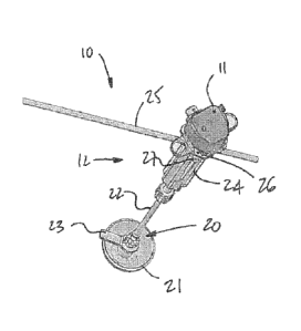
Kom Fig. 1 is a perspective view of a pelvic digitizer
device with inertial sensor unit in accordance with an
embodiment of the present disclosure;
- 4 -
CA 02866192 2014-09-03
WO 2014/019086
PCT/CA2013/050589
[0027] Fig. 2
is a series of figures showing variants of
a cup and stopper of the pelvic digitizer device of Fig. 1;
[COM Fig. 3
is a perspective view of the pelvic
digitizer device relative to a pelvis in accordance with a
method of the present disclosure;
[0029] Fig. 4
is a radiographic image of a pelvis showing
an angle between acetabulum line and medio-lateral axis; and
VON Fig. 5
is a perspective view of a tracker device
with inertial sensor unit as used with the pelvic digitizer
device of Fig. 1.
DESCRIPTION OF THE EXEMPLARY EMBODIMENTS
[0031]
Referring to the drawings and more particularly to
Fig. 1, there is a pelvic digitizer device in accordance
with the present disclosure at 10. The device 10 is of the
type used with an inertial sensor unit 11 mounted on a tool
body 12. The
inertial sensor unit 11 may be known as a
sourceless sensor, a micro-electromechanical sensor unit
(MEMS unit), and has any appropriate set of inertial sensors
(e.g., accelerometers, gyroscope) to produce tracking data
in at least three degrees of rotation (i.e., the orientation
about a set of three axes is tracked). The sensor unit 11
may be self enclosed in a pod that is connectable in an
accurate and predetermined manner to the tool body 12 of the
device 10.
[0032] The tool
body 12 has a tool end 20 in the shape of
a cup 21. The cup
21 is shaped to match the shape of an
acetabulum (e.g., a hemisphere or quasi-hemisphere), and the
size of the cup 21 may be selected as a function of pre-
operative imaging of the acetabulum, as will be described
hereinafter. For this purpose, the cup 21 may be releasably
connected to a shaft 22 of the tool body 12, such that a cup
21 of appropriate dimension may be selected. A stopper 23
is integral with the cup 21, and may have different
configurations as is shown in Fig. 2, including a pointy
edge. Moreover, the stopper 23 may rotate relative to the
- 5 -
CA 02866192 2014-09-03
WO 2014/019086
PCT/CA2013/050589
shaft 22, to be turned to a desired orientation to contact
bone landmarks.
[0033] A handle
24 is located at an opposite end of the
cup 21 on the shaft 22. The
handle 24 is ergonomically
configured to be handled by a user. A visual guide 25 is a
rod that projects transversally from the handle 24. The
visual guide 25 is used to visually guide the user in
aligning the device 10 with the body of the patient. In an
alternative embodiment, the visual guide 25 is a laser or
LED light source that emits a visual line for guidance.
VON A
receptacle 26 is located at the end of the
handle 24, and is configured to receive the sensor unit 11
in the accurate and predetermined manner.
Alternatively,
the sensor unit 11 may be built-in to the tool body 12.
However, in both cases, an orientation of the sensor unit 11
is preset relative to the tool body 12, such that tracking
about at least one axis (one rotational degree of freedom)
is known when the sensor unit 11 is initialized. According
to an embodiment, the shaft 22 and the visual guide 25 lie
in a plane of the device 10, and the preset orientation of
the sensor unit 11 has its axis normal to the plane of the
device 10. In other
words, when the sensor unit 11 is
initialized, for instance by pressing on the button 27, an
axis of the sensor unit 11 will be normal to the plane of
the device 10 in which the shaft 22 and the visual guide 25
(or light line produced thereby) lie.
[0035] Although
not shown, the sensor unit 11 may be
equipped with visual interfaces to provide data to a user
(e.g., LEDs of different colors, such as green and red), or
may be connected to a computer-assisted surgery system to
transmit the orientation data thereto. The transmission of
data may be wireless, in any appropriate protocol (e.g.,
Bluetooth, ZigBee, etc).
[0036] Now that
the device 10 has been described, a
method of using the device 10 to create a pelvic frame of
reference (a.k.a., pelvic coordinate system) is set forth.
- 6 -
CA 02866192 2014-09-03
WO 2014/019086
PCT/CA2013/050589
[0037]
According to a pre-operative step, the frontal
plane of the pelvis of the patient is imaged using any
appropriate type of imaging (e.g., X-ray), to obtain an
image as in Fig. 4. From this image, angle (I may be
obtained (shown as 40 degrees), as the acetabulum line,
i.e., the line crossing portions of the rim of the
acetabulum, relative to the medio-lateral axis (hereinafter
ML axis). The ML
axis may be the line that connects 2
antero-superior iliac spine (ASIS) points or connects the
bottom of two teardrops of the pelvis, as shown in Fig. 4.
Also, from the image, the cup size that fits the patient's
native acetabulum may be evaluated.
VON The next
steps are performed intra-operatively,
with the device 10 being equipped with a sensor unit 11 with
preset orientation and the cup 21 dimensioned to match the
pre-operative evaluated size. Referring to Fig. 3, with the
patient in a strict lateral decubitus (e.g., with the
frontal plane being aligned with gravity) with the frontal
plane being perpendicular to the substantially horizontal
surface of the operating table, for instance as eyeballed
using pelvic landmarks, and with the femur being dislocated
from the acetabulum, the cup 21 of the device 10 is inserted
in the native acetabulum before it is reamed. The stopper 23
is abutted against the rim of the acetabulum to ensure that
the cup 21 is properly inserted in the acetabulum. For
example, the device 10 may be waggled back-and-forth in the
patient's acetabulum, while keeping the instrument moving in
the patient frontal plane. The waggle motion will be stopped
by the stopper 23 on the modular cup 21. In the embodiment
of the device 10, the stopper 23 points towards the
patient's head, but may be configured and rotated to point
toward the patient's feet, etc, as a matter of preference of
the surgeon, considering the environing soft tissue. The
stopper 23 can be adjustable as to where it is located, so
that it adapts to the user's preferences. However, there are
few bone landmarks, e.g. acetabulum notch, and it is
preferred that the stopper 23 cooperates with these
- 7 -
CA 02866192 2014-09-03
WO 2014/019086
PCT/CA2013/050589
landmarks, whereby the orientation of the stopper 23 may be
adjusted relative to the shaft 22 to align the stopper 23
with the bone landmarks.
[0039] When the
stopper 23 contacts the rim of the
acetabulum, the visual guide 25 may be visually aligned with
the patient's frontal plane. For example, the visual guide
25 (whether a rod or a linear light beam) is pointed towards
the patient's head and parallel to the longitudinal axis of
the patient. This direction may be arranged to be parallel
to the long side of the operating table. The visual guide
25 gives a visual indication to keep the device 10 moving in
a plane that is parallel to the patient's frontal plane.
[0040] With the
visual guide 25 held in such a way that
it is generally parallel to the frontal plane of the
patient, the sensor unit 11 may be turned on. In the
illustrated embodiment, the "on" button 27 is conveniently
located on the handle 24. The sensor unit 11 is preset with
an orientation, in such a way that orientation about a first
rotational degree of freedom is known when the sensor unit
11 is initialized. More specifically, when the sensor unit
11 is turned on, an axis of the sensor unit 11 is normal to
the plane of the device 10. As the plane of the device 10
is parallel to the frontal plane of the patient as a result
of the steps set forth above on patient positioning and
maneuvering of the device 10, the sensor unit 11 has a
preset axis aligned with the anterior-posterior (AP) axis of
the patient.
[0041] The ML axis is then set. As the
stopper 23 is
stuck on the rim of the acetabulum and the device 10 is
maintained parallel to the patient frontal plane, the rim of
the modular cup 21 is aligned with the acetabulum line
(Fig. 4), the shaft of the acetabulum is perpendicular to
rim of the modular cup. At this time, the inertial sensor
unit 11 will be able to compute the ML axis based on the
preoperatively obtained a angle and the known geometrical
relation between the inertial sensor unit 11 and the tool
body 12 from the preset instrumental parameters. The
- 8 -
CA 02866192 2014-09-03
WO 2014/019086
PCT/CA2013/050589
computation may be done by rotating the shaft 22 of the
device 10, which is known to the inertial sensor unit 12, by
90-alpha degrees. A
command must be given to the sensor
unit 11 that the ML axis will be set. These rotations will
allow the sensor unit 11 to set the ML axis.
[0042] Finally,
the cranial-caudal (CC) axis is the
cross-product of the AP axis and the ML axis. With the
three axes set in the manner described above, the device 10
is calibrated as a frame of reference about three rotational
axes is created between the device 10 and the pelvis.
[0043] As
alterations will be made to the acetabulum, the
coordinate system must be transferred from the sensor unit
11 on the device 10 to a sensor unit of a tracking device
30, as shown in Fig. 5. The
tracking device 30 is secured
to the pelvis for instance in the receptacle 30A shown, and
has a sensor unit 31 of similar nature and configuration as
the sensor unit 11 of the device 10. The
inertial sensor
unit 31 has a preset orientation for instance with an axis
being aligned with a surface of the receptacle 30A, such
that the axis is parallel to gravity when the surface of the
receptacle 30A is horizontal. According to an embodiment,
the tracking device 30 is pinned to the iliac crest. The
tracking device 30 is then aligned with the horizon, using
the readings from the sensor unit 31. The sensor unit 31 is
the equivalent of "bubble" levels being orthogonal to each
other. In an embodiment, the sensor unit 31 is connected to
a body of the tracking device 30 by a ball joint 32 (or like
three rotational DOF joint), to allow such horizontal
leveling (and hence for an axis to be parallel to gravity).
The various DOFs of the joint 32 may be locked.
[0044] With it
being level, the sensor unit 31 is rotated
around its normal axis to align a visual guide 33 thereof,
such as a rod, with the patient's frontal plane, with these
rotations being recorded by the sensor unit 31.
Accordingly, the tracking device 30 is aligned with the
frontal plane, whereby the AP axis is now common to both the
devices 10 and 30. In this
orientation of the tracking
- 9 -
CA 02866192 2014-09-03
WO 2014/019086
PCT/CA2013/050589
device 30, the pelvic coordinate system may be transferred
from the sensor unit 11 of the device 10 to the sensor unit
31 of the tracking device 30. The
transfer is performed
using the common vectors measured by both sensor units 11
and 31, respectively of the device 10 and the device 30, to
build an equation. The common vectors are the AP-axis and
gravity. The equation is solved, and the relation between
the tracking device 30 and the patient coordinate system of
the sensor unit 11 can be found, to complete the pelvis
registration.
[0045]
According to another embodiment, the operating
table is rotatable about its transverse axis, i.e., about an
axis that is generally normal to the frontal plane of the
patient in the strict lateral decubitus. The
rotation of
the table is used to transfer the pelvic coordinate system
from the device 10 to the tracking device 30. To
perform
such transfer, the device 10 is removed from engagement in
the patient's acetabulum. The
table is rotated while
ensuring that the patient remains generally immovable
relative to the table surface. In an
embodiment, the OR
table is rotated about 0 , remains stable for 15 secs, and
then rotated back. While
rotating the table, with the
tracking device 30 secured to the pelvis of the patient, the
readings of the sensor unit 31 are recorded. A
tracking
device on a table locator, detects the rotation angle (0)
and the rotation axis (r-axis). The expected readings of the
device 10 can be mathematically calculated: rotation of
tracking device x, y, z axes of the device 10 respectively
{around r-axis, with 0 } as if the device 10 was
mechanically attached to the pelvis and followed the
rotation of the OR table. The patient coordinate system may
be transferred from the device 10 to the tracking device 30.
The readings of both sensor units 11 and 31 in a first
position and second position are used, with the first
position being after the calibration of the device 10, and
the second position being with the OR table inclined by 0
(using in this case the expected reading for the device 10).
-10-
CA 02866192 2014-09-03
WO 2014/019086
PCT/CA2013/050589
[0046] Once the
frame of reference of the pelvis is
transferred to the pelvic tracking device 30, the pelvis may
be tracked in orientation about three rotational degrees of
freedom, and this tracking may be used and transferred to
tools for instance to determine the anteversion and
abduction/adduction angles of these tools. The
tools may
include reamers, impactors, etc.
[0047] The
proposed method using the device 10 requires
only the patient frontal plane to be aligned with gravity
(i.e. the roll angle of the pelvis is required to be zero;
however, tilt angle can be arbitrary).
Moreover, the
proposed method uses only one radiograph, i.e. the frontal
plane X-ray. Moreover, the proposed method is a calibration
of the devices 10 and 30 performed intra-operatively.
-11 -