Sélection de la langue

Search

Sommaire du brevet 2866236 

Énoncé de désistement de responsabilité concernant l'information provenant de tiers

Une partie des informations de ce site Web a été fournie par des sources externes. Le gouvernement du Canada n'assume aucune responsabilité concernant la précision, l'actualité ou la fiabilité des informations fournies par les sources externes. Les utilisateurs qui désirent employer cette information devraient consulter directement la source des informations. Le contenu fourni par les sources externes n'est pas assujetti aux exigences sur les langues officielles, la protection des renseignements personnels et l'accessibilité.

Disponibilité de l'Abrégé et des Revendications

L'apparition de différences dans le texte et l'image des Revendications et de l'Abrégé dépend du moment auquel le document est publié. Les textes des Revendications et de l'Abrégé sont affichés :

  • lorsque la demande peut être examinée par le public;
  • lorsque le brevet est émis (délivrance).
(12) Brevet: (11) CA 2866236
(54) Titre français: RACCORD DE RAVITAILLEMENT EN CARBURANT
(54) Titre anglais: REFUELLING COUPLING
Statut: Octroyé
Données bibliographiques
(51) Classification internationale des brevets (CIB):
  • B60K 15/04 (2006.01)
  • B60K 15/03 (2006.01)
  • B60K 15/035 (2006.01)
  • F16L 37/30 (2006.01)
(72) Inventeurs :
  • REMFRY, LEIGH MAXWELL (Royaume-Uni)
(73) Titulaires :
  • REMFRY, LEIGH MAXWELL (Royaume-Uni)
(71) Demandeurs :
  • REMFRY, LEIGH MAXWELL (Royaume-Uni)
(74) Agent: BRION RAFFOUL
(74) Co-agent:
(45) Délivré: 2020-01-21
(86) Date de dépôt PCT: 2013-04-12
(87) Mise à la disponibilité du public: 2013-09-12
Requête d'examen: 2018-04-12
Licence disponible: S.O.
(25) Langue des documents déposés: Anglais

Traité de coopération en matière de brevets (PCT): Oui
(86) Numéro de la demande PCT: PCT/GB2013/000168
(87) Numéro de publication internationale PCT: WO2013/132215
(85) Entrée nationale: 2014-09-03

(30) Données de priorité de la demande:
Numéro de la demande Pays / territoire Date
1204243.8 Royaume-Uni 2012-03-09
1207053.8 Royaume-Uni 2012-04-20

Abrégés

Abrégé français

L'invention concerne un raccord de ravitaillement en carburant qui possède un raccord annulaire (1) présentant un alésage (2), des tenons de baïonnette (3) et des fentes (4) le rendant adapté à être raccordé à une buse de remplissage sous pression (50). Un élément de raccord rapide (5) est prévu à l'intérieur du raccord annulaire, assurant normalement l'étanchéité sur celui-ci avec l'aide d'un joint d'étanchéité torique (6). Lorsque la buse de remplissage sous pression est installée, l'élément de raccord rapide est enfoncé permettant au carburant de s'écouler. L'élément de raccord rapide présente une ouverture centrale (11), normalement fermée par un volet de côté qui pivote (12). Le pivot (14) se fait sur un axe (15) porté par les tenons (16) sur la face inférieure d'un disque central (17) présentant l'ouverture (11). Le volet possède un doigt (17) se projetant entre les tenons et possédant l'axe le traversant. Un ressort (18) est solidaire de l'axe et sollicite normalement le volet dans sa position fermée parallèle au disque. Un joint torique (19) est monté sur le volet, grâce à quoi il ne fuit pas, dans le cas où des forces inhabituelles auraient pour effet de déplacer le carburant contre le volet. Pour l'avitaillement en carburant par gravité par buse, une buse d'avitaillement en carburant par gravité (52) est placée contre le volet et poussée contre son ressort. Le ravitaillement en carburant peut maintenant se produire.


Abrégé anglais


A refuelling coupling has an annular fitting (1) having a bore (2), bayonet
lugs (3) and slots (4) suiting it for
connection to a pressure filling nozzle (50). A dry-break member (5) is
provided within the annular fitting, normally sealing to it with the
aid of an O-ring seal (6). When the pressure filling nozzle is fitted, the dry-
break member is depressed allowing fuel to flow. The
dry-break member has a central aperture (11), normally closed by a side
pivoted flap (12). The pivot (14) is at a pin (15) carried in
lugs (16) on the underside of a central disc (17) having the aperture (11).
The flap has a finger (17) projecting between the lugs and
having the pin passing through it. A spring (18) is carried on the pin and
normally biases the flap into its closed position parallel
with the disc. An O-ring (19) is carried on the flap whereby should unusual
forces displace fuel against the flap it does not leak. For
gravity nozzle fuelling, a gravity fuelling nozzle (52) is placed against the
flap and pushed in against its spring. Refuelling can now
occur.

Revendications

Note : Les revendications sont présentées dans la langue officielle dans laquelle elles ont été soumises.


8

What is claimed is:

1. A refuelling coupling having:
.cndot. an annular member,
.cndot. a fitting on the annular member complementary to a pressure
refuelling nozzle and
.cndot. a displaceable dry-break member in the coupling for normally sealing
the coupling via a
seal between the annular member and the dry-break member, the dry-break member
being
displaceable from its sealing position on connection of a pressure refuelling
nozzle, the dry-break
member including:
.cndot. an aperture in the displaceable dry-break member and
.cndot. a subsidiary displaceable member carried by the dry-break member,
this member
normally closing the aperture and being displaceable by introduction of a
gravity refuelling
nozzle into the aperture.
2. The refuelling coupling as claimed in claim 1, wherein the subsidiary
displaceable
member is translationally displaceable with respect to the displaceable dry-
break member against
a subsidiary return spring.
3. The refuelling coupling as claimed in claim 1, wherein the subsidiary
displaceable
member is pivotally displaceable with respect to the displaceable dry-break
member against a
subsidiary return spring.
4. The refuelling coupling as claimed in claim 3, wherein the subsidiary
return
spring is a torsion spring arranged to act about a pivot about which the
subsidiary displaceable
member is pivotally displaceable.
5. The refuelling coupling as claimed in any one of claims 1 to 4,
including a second
seal for sealing of the subsidiary member to the dry-break member, whereby
full dry-break
operation is available when pressure refuelling.


9

6. The refuelling coupling as claimed in any one of claims 1 to 5, wherein
the
displaceable dry-break member is translationally displaceable in the coupling
against at least one
main return spring.
7. The refuelling coupling as claimed in claim 6, including a plurality of
rods
secured in the coupling and on which the dry-break member is displaceably
carried, the main
return springs being mounted on the rods and acting against abutments at the
ends of the rods
remote from the dry-break member.
8. The refuelling coupling as claimed in claim 7, wherein the abutments are

provided by an abutment member in the form of a spider or a ring
interconnecting the remote
ends of the rods.
9. The refuelling coupling as claimed in any one of claims 7 and 8,
including:
.cndot. an annular rim or lip on or sealingly connectable to the annular
member,
.cndot. a second annular rim or lip member connectable to a wall of a fuel
tank and
.cndot. a sleeve or hose securable to the annular rim for extension around
the rods and to the
second annular rim or lip member.
10. The refuelling coupling as claimed in claim 7, including a sleeve
integrally or
fixedly extending back from the annular member, the abutments being provided
on the sleeve
remote from the annular member.
11. The refuelling coupling as claimed in any one of claims 1 to 10,
including:
.cndot. an air vent having a float arranged to close as a tank fills for
causing back- pressure in the
nozzle when the tank is full and
.cndot. an airflow restricter in a duct of the air vent, the restricter
being adapted to open to a
limited extent to accommodate gravity refuelling air escape and to a greater
extent to allow an
increased air flow in the case of pressure refuelling.
12. The refuelling coupling as claimed in claim 11, wherein the
restricter has:


10

.cndot. an apertured sleeve mounted in the duct for movement axially
thereof,
.cndot. a first spring mounted on the sleeve for urging it against the
direction airflow in the duct
on refuelling;
.cndot. a first disc carried by the sleeve and a seat in the duct, the
spring normally urging the disc
into contact with the seat to close the duct;
- an inner member mounted in the sleeve for movement axially thereof;
.cndot. a secondary spring mounted on the inner member a spring mounted on
the sleeve for
urging it against the direction airflow in the duct on refuelling;
.cndot. a secondary disc smaller than the first disc, carried by the inner
member, and a secondary
seat on the first disc around an aperture therein, the secondary spring
normally urging the
secondary disc into contact with the secondary seat to close the first disc,
the restricter being arranged such that on low air flow in the duct, as in
gravity refuelling,
the secondary disc moves from the secondary seat against the secondary spring
and on high air
flow in the duct, as in pressure refuelling, the first disc moves from the
seat in the duct against
the first duct.
13. An adapter for a refuelling coupling as defined in any one of claims
1 to 12, the
adapter being generally tubular and having:
.cndot. a first fitting at one end complementary to a pressure refuelling
nozzle,
.cndot. a second fitting at an other end complementary to that on annular
member and
.cndot. a shuttle extending between the ends of the adapter, the shuttle
being adapted and
arranged to be displaced by a displacement member of the pressure refuelling
nozzle and to
displace the displaceable dry-break member.
14. The adapter as claimed in claim 13, wherein the shuttle has a spring
urging it
towards the first fitting.
15. The adapter as claimed in claim 14, wherein the shuttle has:
.cndot. a first dry-break piston at the one end adapted to be urged by the
spring against a seat in
the adapter in sealing engagement with the one end of the adapter and


11

.cndot. a second dry-break piston at the other end adapted to slidingly
seal with the other end of
the adapter when the first dry-break piston is against said seat,
the shuttle being arranged such that for refuelling with the shuttle
displaced, the first dry-break
piston is moved off said seat and the second dry-break piston is moved out of
sealing with the
other end of the adapter.

Description

Note : Les descriptions sont présentées dans la langue officielle dans laquelle elles ont été soumises.


CA 02866236 2014-09-03
WO 2013/132215
PCT/GB2013/000168
REFUELLING COUPLING
The present invention relates to a refuelling coupling.
Road vehicles are usually refuelled with a so-called "gravity" refuelling
nozzle
to which fuel is pumped under pressure, but from which the fuel flows under
gravity
into a vehicle's filler neck or refuelling coupling.
Many air-borne and some other vehicles are refuelled with a pressure
Jo refuelling nozzle, which is fluid-tightly connected to the vehicle's
refuelling coupling.
Some vehicles do indeed include both types of refuelling coupling. This is
expensive, bulky and introduces a weight penalty on an aircraft.
As used herein, the term coupling is used to mean the vehicle side connector;
whereas the term nozzle is used to mean the refuelling vessel and refuelling
side
connector. We are aware that this terminology is not universal and that in
other
regions the term coupler is used to mean the hose side connector.
= Also as used herein, the term dry-break is used to mean that the coupling
and
nozzle are adapted to be both sealed when not connected to each other.
The object of the present invention is to provide a combined pressure and =
gravity refuelling coupling.
According to a first aspect of the invention there is provided a refuelling
coupling having:
= an annular member,
= a fitting on the annular member complementary to a pressure refuelling
nozzle
and
= a displaceable dry-break member in the coupling for normally sealing the
coupling via a seal between the annular member and the dry-break member,

CA 02866236 2014-09-03
WO 2013/132215
PCT/GB2013/000168
2
the dry-break member being displaceable from its sealing position on
connection of a pressure refuelling nozzle, the dry-break member including:
= an aperture in the displaceable dry-break member and
= a subsidiary displaceable member carried by the dry-break member, this
member normally closing the aperture and being displaceable by
introduction of a gravity refuelling nozzle into the aperture.
Normally the main displaceable dry-break member will be translationally
displaceable against a return spring. Such an arrangement is possible for the
subsidiary displaceable member. However in the interests of allowing the
"gravity"
nozzle to penetrate past the subsidiary displaceable member, the latter is
preferably
pivotally connected to the main dry-break member. Conveniently, the pivot is
provided with a spring for returning the subsidiary member to its normally
closed
position. Preferably the main and subsidiary members are adapted for sealing
of the
subsidiary member to the main member, whereby full dry-break operation is
available
when pressure refuelling.
Insofar as the coupling may be provided separate from a fuel tank, that is in
a
vehicle skin, and/or the tank may be flexible, the main dry-break member is
preferably mounted on rods extending from fitting and having springs for
returning
the dry-break member back the to the fitting and a hose is provided around the
rods
for connection to both the fitting and the tank. The inner ends of the rods
can be
carried on the annular member or at least a sleeve being an integral extension
of the
annular member or on an abutment member in the form of a spider or a ring.
Preferably the coupling is provided with an air vent having a float arranged
to
close as the tank fills for causing back-pressure in the connector when the
tank is full.
Additionally an airflow restricter is preferably provided in an air vent duct.
The
restricter is preferably adapted to open to a limited extent to accommodate
gravity
.. refuelling air escape and to a greater extent to allow an increased air
flow in the case
of pressure refuelling, with its great fuel flow.

CA 02866236 2014-09-03
WO 2013/132215
PCT/GB2013/000168
3
According to a second aspect of the invention, there is provided an adapter
for
a refuelling coupling as claimed in any preceding claim, the adapter being
generally
tubular and having:
= a fitting at one end complementary to a pressure refuelling nozzle,
= a fitting at the other end complementary to that on annular member and
= a shuttle extending between the ends of the adapter, the shuttle being
adapted
and arranged to be displaced by a displacement member of the pressure
refuelling nozzle and to displace the displaceable dry-break member.
To help understanding of the invention, a specific embodiment thereof will
now be described by way of example and with reference to the accompanying
drawings, in which:
Figure 1 is a cross-sectional side view of a refuelling coupling of the
invention installed in the skin of a vehicle (not shown) and connected to a
fuel tank;
Figure 2 is a perspective view of the coupling as such;
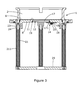
Figure 3 is a side view of the coupling of Figure 2;
Figure 4 is a view similar to Figure 1 in preparation for refuelling with a
gravity nozzle;
Figure 5 is a similar view during gravity nozzle refuelling;
Figure 6 is another such view in preparation for pressure nozzle refuelling;
Figure 7 is a similar view during pressure nozzle refuelling;
Figure 8 is a view similar to Figure 1 of a varied refuelling coupling;
Figure 9 is a similar view during gravity nozzle refuelling;
Figure 10 is a similar view during pressure nozzle refuelling;
Figure 11 is another view showing the finish of pressure nozzle refuelling;
Figure 12 is a partially sectioned, perspective view of another refuelling
coupling of the invention;
Figure 13 is a partially sectioned vie w of an adapter for a refuelling
coupling
of the invention
Figure 14 , Figure 15 and Figure 16 are cross-sectional side views in the
attachment and refuelling use of a pressure refuelling nozzle to the
refuelling coupling
of Figure 12 via the adapter of Figure 13 and
Figure 17 is a variant of the coupling of Figure 2..

CA 02866236 2014-09-03
WO 2013/132215
PCT/GB2013/000168
4
Referring to the drawings, the refuelling coupling there shown has an annular
fitting 1 having a bore 2, bayonet lugs 3 and slots 4 suiting it for
connection to a
pressure filling nozzle 50. A dry-break member 5 is provided within the
annular
fitting, normally sealing to it with the aid of an 0-ring seal 6. When the
pressure
filling nozzle is fitted, the dry-break member is depressed allowing fuel to
flow. In
this respect, the refuelling coupling is conventional.
In accordance with the invention, the dry-break member has a central aperture
11, normally closed by a side pivoted flap 12. The pivot 14 is at a pin 15
carried in
lugs 16 on the underside of a central disc 17 having the aperture 11. The flap
has a
finger 17 projecting between the lugs and having the pin passing through it. A
spring
18 is carried on the pin and normally biases the flap into its closed position
parallel
with the disc. An 0-ring 19 is carried on the flap whereby should unusual
forces
displace fuel against the flap it does not leak.
For gravity nozzle fuelling, as shown in Figure 4 & 5, a gravity fuelling
nozzle
52 is placed against the flap and pushed in against its spring. Refuelling can
now
occur.
The fitting 1 has three rods 21 secured to the underside of a fixture rim 22.
The dry-break member has three projections 23 with bores 24 through which the
rods
project. Lower ends of the rods are fast in a spider 25. The rods carry
springs 211
which normally bias the dry-break member into sealing contact with the fitting
1.
For pressure refuelling, the pressure refuelling nozzle 50 is latched on and
operated to cause its dry-break member 501 to physically displace the member 5
for
flow of fuel around it. Should de-fuelling be required through a pressure
refuel
nozzle, in the case of the vehicle having the refuelling coupling, it should
be noted
that the flap12/disc17 does not inhibit this because scavenged fuel can flow
around
the dry break member 5 which is displaced from its seat in the annular fitting
1.
In the embodiment of Figures I to 7, the fitting is fast in the skin 53 of a
vehicle, with the skin being sandwiched between the rim 22 and a ring 26. The
ring

CA 02866236 2014-09-03
WO 2013/132215
PCT/GB2013/000168
has a rim 27. A similar rim 28 is provided on a closure plate 29 of a fuel
tank 54.
Extending between the lips 27 & 28 is a flexible hose 30, held to the rims by
screwed
bands 31. Thus fuel flow is directed into the tank which is allowed some
deflection
within the skin 53 or vice versa. A strainer 32 is shown extending from the
spider 25
5 into the tank.
Also mounted in the tank plate 29 is an air vent 33 in the form of a duct 34
secured via a rim 35. Tube carries an apertured ball retainer 36 which retains
a
buoyant ball 37 and a dense ball 38. The latter is for forcing the buoyant
ball to seal
in a vehicle inversion. The buoyant ball seals during refuelling by floating
against a
seat 39 above the cage. Above the seat, an airflow limiting disc 40 is urged
against
the seat by a spring 41. The disc is open centrally 43 and carried on an
apertured
sleeve 42 carrying the spring 41. The sleeve is secured by a cross pin 44,
against
which the spring reacts. Internally of the sleeve a second spring 45 urges a
inner
sealing disc 46 into the central opening 43 of the disc 40. Features 42, 45 &
46 are
shown in Figure 8.
During gravity nozzle filling air pressure lifts the inner disc 46 against the

light spring 45 and flows through the disc and up through the apertures 42 in
the
sleeve. Thus a pressure marginally above ambient is maintained in the tank,
for quick
closure of the nozzle's trigger when the tank is filled to the extent that the
buoyant
ball 37 seals against the seat 39.
When pressure nozzle filling, the air flow is too great for the apertured
sleeve
and the air pressure in the tank lifts the disc 40. The latter with the action
of its spring
41 keeps the pressure just above ambient, for again causing the fuel flow to
be shut
off by detection of pressure rise when the buoyant float seals.
To vent tank air to atmosphere, a hose 47 extends up from the vent 33 via a
deflector 48. This and the fitting 1 are housed in a depression 55 in the
skin. A
hinged closure 56 is provided for closing the depression, whereby the external
lines of
the vehicle are little disturbed by the single refuelling fitting of the
invention.

CA 02866236 2014-09-03
WO 2013/132215
PCT/GB2013/000168
6
Alternatively to the above use of hoses, the fitting can be fast with a tank
via
its rim 22.
The invention is not intended to be restricted to the details of the above
described embodiment. For instance, as shown in Figures 8 to 11, the rim 22 of
the
fitting 1 can be more extensive as a plate 122 having the air vent 133
attached directly
to it. Also in this arrangement, the skin 53 of the vehicle has an in-turned
lip 155 to
which a collar 161 is attached. The collar has a radially inwards extending
flange
162. This is secured to the plate 122 and to the fuel tank 154. A detail shown
in these
figures is a cap 163 for closing the fitting once the refuelling nozzle is
removed. This
is in addition to the hinged closure 146, which closes over the cap when fined
to the
fitting.
Further, as shown in Figure 12, the ring or at least lugs 226 carrying the end
of
the rods, the hose and the lip can be integral part of the fitting 201 adapted
for
connection to a pressure filling nozzle, or at least these features can be
provided as
two parts, namely the fitting 201 and a main sleeve 202 housing the rods 221
and
springs 211. In this variant, the main sleeve is threaded 203 for connection
to fuel
tank.
Figures 13 to 16 show an adapter for adapting the refuelling coupling to a
pressure refuelling nozzle of a different size. Essentially the adapter 301 is
generally
tubular with a male fitting 302 at one end complementary to a pressure
refuelling
nozzle 303 and a female fitting 303 at the other end, which is complementary
to the
coupling fitting 301. Within the adapter is a shuttle 304, biased by a spring
305 for a
male end piston 306 to seal the male tubular end and a female end piston 307
to seal
the female tubular end. The shuttle is displaced on refuelling to release the
seals and
allow fuel to flow.
The male-end piston 306 is flat for dry-break co-operation with a displacement
member 308 of the pressure refuelling nozzle 309. It carries a peripheral
sealing 0-
ring 310 on its periphery 311, which is tapered for abutting with a seat 312
in the
adapter. This abutment determines the position of the piston 306 under the
action of
the spring 305. Towards the other end of the adapter, it has a spider 313 with
a

CA 02866236 2014-09-03
WO 2013/132215
PCT/GB2013/000168
7
central aperture for a rod 314 inter-connecting the piston 306,307. The spring
acts
between the spider and the inner side of the piston 306.
The piston 307 is similar in having an 0-ring 315 carried in its parallel
periphery 316. The adapter has a parallel bore 317 at this end, with which the
piston
307 seals when in its normal position. On refuelling use, the female-end
piston 307
moves out of the bore 317, and co-operates in a dry-break manner with the
member
310 of the refuelling coupling.
The invention is not intended to be restricted to the details of the above
described embodiments. For instance as shown in Figure 17, the spider 25 of
the
coupling of Figure 2, holding the bottom ends of the rods 21 and against which
the
springs 211, can be replaced with a ring 425, equally holding rods 421 and
providing
abutment for the springs 4211. The advantage of the ring is that it enables
fuel to be
scavenged from a disabled vehicle by another vehicle fitted with a long pipe
(not
shown) at the end of a scavenge hose and pump system, the long pipe being able
to be
passed through the coupling's pivoted disc or flap 417 and through that the
ring 425
towards the bottom of the tank of the vehicle having the coupling 425 and from
which
fuel is being scavenged.

Dessin représentatif
Une figure unique qui représente un dessin illustrant l'invention.
États administratifs

Pour une meilleure compréhension de l'état de la demande ou brevet qui figure sur cette page, la rubrique Mise en garde , et les descriptions de Brevet , États administratifs , Taxes périodiques et Historique des paiements devraient être consultées.

États administratifs

Titre Date
Date de délivrance prévu 2020-01-21
(86) Date de dépôt PCT 2013-04-12
(87) Date de publication PCT 2013-09-12
(85) Entrée nationale 2014-09-03
Requête d'examen 2018-04-12
(45) Délivré 2020-01-21

Historique d'abandonnement

Il n'y a pas d'historique d'abandonnement

Taxes périodiques

Dernier paiement au montant de 347,00 $ a été reçu le 2024-04-08


 Montants des taxes pour le maintien en état à venir

Description Date Montant
Prochain paiement si taxe générale 2025-04-14 347,00 $
Prochain paiement si taxe applicable aux petites entités 2025-04-14 125,00 $

Avis : Si le paiement en totalité n'a pas été reçu au plus tard à la date indiquée, une taxe supplémentaire peut être imposée, soit une des taxes suivantes :

  • taxe de rétablissement ;
  • taxe pour paiement en souffrance ; ou
  • taxe additionnelle pour le renversement d'une péremption réputée.

Les taxes sur les brevets sont ajustées au 1er janvier de chaque année. Les montants ci-dessus sont les montants actuels s'ils sont reçus au plus tard le 31 décembre de l'année en cours.
Veuillez vous référer à la page web des taxes sur les brevets de l'OPIC pour voir tous les montants actuels des taxes.

Historique des paiements

Type de taxes Anniversaire Échéance Montant payé Date payée
Le dépôt d'une demande de brevet 400,00 $ 2014-09-03
Taxe de maintien en état - Demande - nouvelle loi 2 2015-04-13 100,00 $ 2014-09-03
Taxe de maintien en état - Demande - nouvelle loi 3 2016-04-12 100,00 $ 2016-03-24
Taxe de maintien en état - Demande - nouvelle loi 4 2017-04-12 100,00 $ 2017-03-23
Requête d'examen 800,00 $ 2018-04-12
Taxe de maintien en état - Demande - nouvelle loi 5 2018-04-12 200,00 $ 2018-04-12
Taxe de maintien en état - Demande - nouvelle loi 6 2019-04-12 200,00 $ 2019-03-14
Taxe finale 2019-11-29 300,00 $ 2019-11-21
Taxe de maintien en état - brevet - nouvelle loi 7 2020-04-14 200,00 $ 2020-03-05
Taxe de maintien en état - brevet - nouvelle loi 8 2021-04-12 204,00 $ 2021-04-05
Taxe de maintien en état - brevet - nouvelle loi 9 2022-04-12 203,59 $ 2022-04-06
Enregistrement de documents 100,00 $ 2023-02-03
Taxe de maintien en état - brevet - nouvelle loi 10 2023-04-12 263,14 $ 2023-04-05
Taxe de maintien en état - brevet - nouvelle loi 11 2024-04-12 347,00 $ 2024-04-08
Titulaires au dossier

Les titulaires actuels et antérieures au dossier sont affichés en ordre alphabétique.

Titulaires actuels au dossier
REMFRY, LEIGH MAXWELL
Titulaires antérieures au dossier
S.O.
Les propriétaires antérieurs qui ne figurent pas dans la liste des « Propriétaires au dossier » apparaîtront dans d'autres documents au dossier.
Documents

Pour visionner les fichiers sélectionnés, entrer le code reCAPTCHA :


Pour visualiser une image, cliquer sur un lien dans la colonne description du document. Pour télécharger l'image (les images), cliquer l'une ou plusieurs cases à cocher dans la première colonne et ensuite cliquer sur le bouton "Télécharger sélection en format PDF (archive Zip)" ou le bouton "Télécharger sélection (en un fichier PDF fusionné)".

Liste des documents de brevet publiés et non publiés sur la BDBC .

Si vous avez des difficultés à accéder au contenu, veuillez communiquer avec le Centre de services à la clientèle au 1-866-997-1936, ou envoyer un courriel au Centre de service à la clientèle de l'OPIC.


Description du
Document 
Date
(yyyy-mm-dd) 
Nombre de pages   Taille de l'image (Ko) 
Taxe finale 2019-11-21 2 40
Page couverture 2020-01-14 1 47
Abrégé 2014-09-03 1 75
Revendications 2014-09-03 3 130
Dessins 2014-09-03 17 385
Description 2014-09-03 7 307
Dessins représentatifs 2014-10-14 1 10
Page couverture 2014-11-27 1 48
Requête d'examen 2018-04-12 1 42
Demande d'examen 2018-12-06 5 184
Modification 2019-02-20 10 255
Revendications 2019-02-20 4 120
PCT 2014-09-03 3 71
Cession 2014-09-03 8 149