Note : Les descriptions sont présentées dans la langue officielle dans laquelle elles ont été soumises.
CA 02872152 2014-10-30
WO 2013/166359 PCT/US2013/039417
SEAL STEM
BACKGROUND OF THE INVENTION
Field of the Invention
[0001] Embodiments of the present invention generally relate to a
downhole seal
arrangement. More particularly, embodiments of the present invention relate to
seal
stem arrangment for reconnecting with a tubular.
Description of the Related Art
[0002] During the life of a well, an operator may decide to reconnect to
a liner.
One method is to insert a tie back string having a seal stem at a lower end
for
establishing pressure integrity with a liner. Figure 1 shows a seal stem
disposed
inside a polish bore receptacle 3 ("PBR") of the liner. The seal stem includes
a
mandrel 10 and three assemblies 11, 12, 13 of Chevron-type seal rings disposed
on a
reduced diameter portion of the mandrel 10. Each assembly 11, 12, 13 includes
upper and lower travel stops 14, 16 attached to the mandrel 10. Two stacks of
oppositely facing Chevron-type seal rings 21, 23 are disposed between the
travel
stops 14, 16. As shown, a stack of upwardly oriented seal rings 21 and a stack
of
downwardly oriented seal rings 22 are disposed on each side of an o-ring 23.
Each
stack may include as many as twenty seal rings 21, 22 to provide adequate
sealing
with the PBR. The Chevron seal rings 21, 22 are oriented in opposite
directions to
seal against differential pressures in either direction.
[0003] One of the drawbacks of this design is a reduced diameter portion
8 is
created to accommodate the seal assemblies 11, 12, 13. The reduced diameter
portion 8 decreases the burst and collapse integrity of the mandrel 10.
Another
drawback is one or more of the seals may roll off the seal stem during
insertion,
removal, or circulation.
[0004] There is a need, therefore, for a seal arrangement that does not
require a
compromise of the integrity of the seal stem. There is also a need for a seal
stem for
reconnecting with a tubular without concerns of the seal rolling off the seal
stem.
CA 02872152 2014-10-30
WO 2013/166359
PCT/US2013/039417
SUMMARY OF THE INVENTION
[0005] In one embodiment, the sealing apparatus includes a mandrel
having at
least two portions; a first portion having a seal ring disposed on an exterior
surface
and a second portion without a seal ring disposed on an exterior surface. In
one
embodiment, the burst and collapse integrity of the first portion is
substantially the
same as the second portion. In another embodiment, the seal ring is disposed
around the first portion.
[0006] In one embodiment, a sealing apparatus for sealing against a
tubular in the
wellbore includes a mandrel having a gland; a seal ring disposed in the gland
for
engaging the tubular; and one or more seal bands disposed in the seal ring. In
another embodiment, the tubular comprises a PBR. In yet another embodiment,
the
gland comprises a groove formed in an outer surface of the mandrel.
[0007] In another embodiment, a method of connecting to a tubular in a
wellbore
includes providing a sealing apparatus having a mandrel having at least two
portions,
wherein the first portion includes a seal ring disposed on an exterior surface
and the
second portion without a seal ring disposed on an exterior surface, and
wherein a
burst integrity of the first portion is substantially the same as the second
portion. In
one embodiment, the method includes engaging the seal ring to an interior of
the
tubular and redistributing a portion of the seal ring along a gap between the
mandrel
and the tubular.
[0008] In another embodiment, a method of connecting to a tubular in a
wellbore
includes providing a sealing apparatus having a mandrel having a gland; a seal
ring
disposed in the gland for engaging the tubular; and one or more seal bands
disposed
in the seal ring. The method also includes engaging the seal ring to an
interior of the
tubular, and redistributing a portion of the seal ring along a gap between the
mandrel
and the tubular, thereby forming a seal with the tubular.
BRIEF DESCRIPTION OF THE DRAWINGS
[0009] So that the manner in which the above recited features of the
present
invention can be understood in detail, a more particular description of the
invention,
briefly summarized above, may be had by reference to embodiments, some of
which
2
CA 02872152 2014-10-30
WO 2013/166359
PCT/US2013/039417
are illustrated in the appended drawings. It is to be noted, however, that the
appended drawings illustrate only typical embodiments of this invention and
are
therefore not to be considered limiting of its scope, for the invention may
admit to
other equally effective embodiments.
[0olo] Figure 1 illustrates a seal stem in the prior art.
[0011] Figure 2 illustrates an embodiment of a seal stem.
[0012] Figure 3 illustrates an enlarged partial view of the seal stem of
Figure 2.
[0013] Figure 4 illustrates an enlarged view of the seal stem after
engagement with
a tubular.
[0014] Figure 5 illustrates an embodiment of a seal stem.
[0015] Figure 6 illustrates an enlarged partial view of the seal stem of
Figure 5.
[0016] Figure 7 illustrates an embodiment of a seal stem.
[0017] Figure 8 illustrates an enlarged partial view of the seal stem of
Figure 7.
DETAILED DESCRIPTION
[0018] The present invention generally relates to a seal assembly for a
downhole
tool. The seal assembly will be described herein in relation to a seal stem
for
reconnecting to a tubular such as a liner. It is to be understood, however,
that the
seal assembly may also be used with other downhole tools. Further, the seal
assembly may be used in a downhole tool that is disposed within a cased
wellbore or
within an open-hole wellbore.
[0019] In one embodiment, a seal assembly includes a mandrel having one
or
more grooves formed on an outer surface. An extrusion resistant seal ring is
disposed in each of the grooves. The seal ring may be used to form a seal with
a
tubular in the wellbore.
[0020] Figure 2 illustrates an embodiment of a seal stem 100. The seal stem
100
may be a tubular connected to a tubular string (not shown) such as a tubing
string. In
another embodiment, the seal stem 100 may be integral with the tubular string.
The
3
CA 02872152 2014-10-30
WO 2013/166359
PCT/US2013/039417
seal stem 100 includes a mandrel 110 and one or more seal assemblies. The seal
stem 100 may be adapted to form a seal with a tubular in the wellbore. For
example,
the seal stem 100 may engage a precise bore tubular such as a polish bore
receptacle ("PBR"). In one embodiment, the precise bore tubular may include a
tubular having a bore machined to a smooth finish, to a predetermined
diameter, or
both. Although embodiments described below make reference to a PBR, it is
contemplated that the seal stem 100 may engage other tubulars in the wellbore.
[0021] The seal stem 100 may include any suitable number of seal
assemblies
120 to create a seal between mandrel 110 and the PBR. Figure 3 is an enlarged
view
of an exemplary seal assembly 120. The seal assembly 120 includes a seal ring
125
disposed in a gland 130. In one embodiment, the gland 130 may be a
circumferential
groove formed in the outer surface of the mandrel 110. Because the wall
thickness of
the mandrel 110 on each side of the seal ring 125 is retained, as indicated by
reference number 108, the burst and/or collapse properties of the mandrel 110
remain
substantially the same. In one embodiment, the seal assemblies 120 may be
molded
and bonded to the gland 120. A bonding material, such as glue, fastener, or
other
attachment means, may optionally be used to attach the seal ring 125 to the
gland
130. Bonding the seal ring 125 in the gland 130 is useful to prevent the seal
ring 125
from becoming unstable and swab off during movement of the seal stem 100. The
seal ring 125 may include an elastomeric material such as poly ether ketone
("PEEK"), polytetrafluoroethylene ("PTFE"), and combinations thereof.
Additionally, a
volume gap (not shown) may be created between the seal ring 125 and a side of
the
gland 130. The volume gap is configured to substantially prevent distortion of
the
seal ring 125 as the seal stem 100 is being inserted into the PBR 162.
[0022] The seal ring 125 includes one or more anti-extrusion bands, such as
a first
seal band 141 (first anti-extrusion band) and a second seal band 142 (second
anti-
extrusion band). As shown, the seal bands 141, 142 are embedded in the seal
ring
125 in an upper corner of each side of the seal ring 125. In one embodiment,
the seal
bands 141, 142 are disposed on an outer circumference of the seal ring 125. In
another embodiment, the seal bands may be a non-elastomeric anti-extrusion
band
for supporting high pressure. In yet another embodiment, the seal bands 141,
142
are springs, such as toroidal coil springs. The seal bands 141, 142 may be
used to
limit the extrusion of the seal ring 125 during expansion of the seal assembly
120.
4
CA 02872152 2014-10-30
WO 2013/166359
PCT/US2013/039417
The seal bands 141, 142 may also be used to limit the extrusion of applied
differential
pressure after expansion of the seal assembly 120.
[0023] Figure 4 shows the seal stem 100 engaged with the PBR 162. When
the
seal ring 125 initially engages the PBR 162, the seal ring 125 changes its
configuration and occupies a portion of the gap 145 between the mandrel 110
and the
PBR 162. As shown in Figure 3, the seal ring 125 includes a protrusion for
contact
with the PBR 162. The protrusion may be any suitable shape such as an arcuate
shape, a contour, or double protrusion. In one embodiment, the protrusion has
a
height above the mandrel 110 that is more than the distance of the gap 145.
Engagement with the PBR 162 causes the elastomeric material of the seal ring
125 to
redistribute along the gap 145 between mandrel 110 and the PBR 162. In
addition, at
least a portion of the anti-extrusion bands 141, 142 is forced outwardly
toward the gap
145 due to the redistribution of the seal ring material. In this position, the
seal bands
141, 142 act as barriers to substantially prevent the extrusion of the seal
ring 125 into
the gap 145 beyond the seal bands 141, 142. In one embodiment, the seal bands
141, 142 are springs, such as toroidal coil springs, which expand radially
outward into
the gap 145 due to the redistribution of the elastomeric material. As the
springs
expand radially outward, the coils of spring act as a barrier to the flow of
the
elastomeric material of the seal ring 125. In this manner, the seal bands 141,
142 in
the seal ring 125 act as an anti-extrusion barriers.
[0024] Embodiments of the seal assemblies 120 described herein provide
several
advantages over the prior art. For example, by preventing extrusion of the
seal ring
125, the seal bands 141, 142 retain the seal ring 125 in an energized state to
create a
high-pressure seal between the seal assembly 120 and the PBR 162. In one
embodiment, the seal assembly 120 may create a high-pressure seal in the range
of
12,000 to 14,000 psi. Another potential benefit is the seal assembly 120 does
not
require the mandrel 110 to include a reduced diameter portion to accommodate
the
seal assembly. As a result, the mandrel 110 has a higher burst and collapse
property.
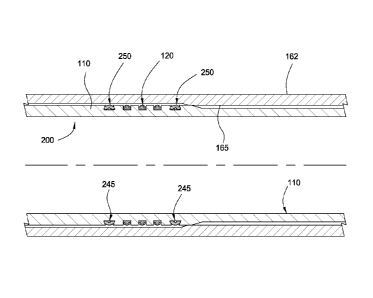
[0025] Figure 5 illustrates an embodiment of a seal stem 200. For
convenience,
the components in the seal stem 200 that are similar to the components in the
seal
stem 100 will be labeled with the same reference number. The seal stem 200
includes the mandrel 110 and the seal assemblies 120. Each seal assembly 120
may
5
CA 02872152 2014-10-30
WO 2013/166359
PCT/US2013/039417
include the first seal band 141 (first anti-extrusion band) and the second
seal band
142 (second anti-extrusion band) as described herein.
[0026] As shown in Figure 5, the seal stem 200 includes a wiper ring 250
disposed
adjacent each end of the seal assemblies 120. The wiper ring 250 is configured
to
wipe (or clean) an inner surface 165 of the PBR 162 as the wiper ring 250
contacts
and slides along the inner surface 165 when the seal stem 200 is inserted into
the
PBR 162. As a result, a clean surface is provided for the seal assemblies 120
when
the seal stem 100 is engaged with the PBR 162. An optional o-ring 245 may be
placed under the wiper ring 250. The o-ring 245 is configured to act as a
stiffener
under the wiper ring 250. In other words, the o-ring 245 stiffens the wiper
ring 250 by
supporting a portion of the wiper ring 250. As shown in Figure 6, the wiper
ring 250 is
disposed in a gland 220. In one embodiment, the gland 250 may be a
circumferential
groove formed in the outer surface of the mandrel 110. The gland 250 is shaped
so
as to provide support to the wiper ring 250 as the wiper ring 250 cleans the
inner
surface 165 of the PBR 162.
[0027] As shown in Figure 6, a volume gap 220 is created between the
seal ring
125 and a side of the gland 130. Generally, the volume gap 220 is used to
substantially prevent distortion of the seal ring 125 as the seal stem 200 is
being
inserted into the PBR 162. The volume gap 220 is a free-space (empty space,
clearance or void) between a portion of the seal ring 125 and a portion of the
gland
130 prior to the insertion of the seal stem 200 into the PBR 162. In other
words,
during the fabrication process of the seal stem 200, the volume gap 220 is
created by
positioning the seal ring 125 within the gland 130 such that the seal ring 125
is
spaced apart from at least one side of the gland 130. Even though the volume
gap
220 in Figure 6 is created by having a side of the gland 130 arranged parallel
to the a
side of the seal ring 125, the volume gap 220 may be created in any
configuration,
such as positioned at an angle, without departing from principles of the
present
invention. Additionally, the size of the volume gap 220 may vary depending on
the
configuration of the gland 130. In one embodiment, the gland 130 has 3-5% more
volume due to the volume gap 220 than a standard gland without a volume gap.
[0028] During the insertion of the seal stem 200 into the PBR 162, the
seal ring
125 moves into contact with the inner surface 165 of the PBR 162 to create a
seal
between the seal stem 200 and the PBR 162. As the seal ring 125 contacts the
inner
6
CA 02872152 2014-10-30
WO 2013/166359
PCT/US2013/039417
surface 165 of the PBR 162, the seal ring 125 changes configuration and
occupies a
portion of the volume gap 220. In one embodiment, the volume gap 220 is
located on
the side of the seal assembly 120 which is the first portion to be in contact
with the
inner surface 165 of the PBR 162. The location of the volume gap 220 in the
seal
assembly 120 allows the seal ring 125 to change position (or reconfigure)
within the
gland 130 during the insertion operation. Additionally, the volume of the
volume gap
220 may change during the insertion operation.
[0029] Figure 7 illustrates an embodiment of a seal stem 300. For
convenience,
the components in the seal stem 300 that are similar to the components in the
seal
stems 100, 200 will be labeled with the same reference number. As shown, the
seal
stem 300 includes multiple sets of seal assemblies 120 on the mandrel 110.
Each set
includes two seal assemblies 120. It should be understood, however, that each
set
may include any number of seal assemblies, without departing from principles
of the
present invention.
[0030] Figure 8 illustrates an enlarged partial view of the seal stem 300
of
Figure 7. As shown, the seal ring 125 includes one or more anti-extrusion
bands,
such as the first seal band 141 (first anti-extrusion band) and the second
seal band
142 (second anti-extrusion band). The seal bands 141, 142 are embedded in the
seal
ring 125 in an upper corner of each side of the seal ring 125. The seal ring
125 is
disposed in the gland 130. Additionally, the volume gap 220 may be created
between
the seal ring 125 and the side of the gland 130. The volume gap is configured
to
substantially prevent distortion of the seal ring 125 as the seal stem 300 is
being
inserted into the PBR (not shown).
[0031] The mandrel 110 has a first outer diameter 325 between each set
of seal
assemblies 120 and a second outer diameter 310 at the seal assemblies 120. The
first outer diameter 325 is smaller than the second outer diameter 310. In
other
words, the mandrel 110 has a greater wall thickness (see reference number 310)
at
the seal assemblies 120 as compared to the wall thickness (see reference
number
325) between each set of seal assemblies 120. The increased wall thickness at
the
seal assemblies 120 provides support to the seal assemblies 120 as the seal
stem
300 is being inserted into the PBR (not shown). Further, the increased wall
thickness
at the seal assemblies 120 minimizes the gap (reference number 145 on Figure
4)
between the mandrel 110 and the PBR. As a result, the smaller gap may be used
to
7
CA 02872152 2014-10-30
WO 2013/166359
PCT/US2013/039417
limit the extrusion of the seal ring 125 as the seal stem 300 is being
inserted into the
PBR. The smaller gap may also be used to limit the extrusion of the seal ring
125
when the seal assemblies 120 are subjected to high differential pressure after
the
seal stem 300 has been inserted into the PBR. In other words, the seal
assemblies
120 will be able to withstand a higher differential pressure above and/or
below the
seal assemblies 120 with the smaller gap, as described herein, as compared to
seal
assemblies that do not have the smaller gap. Moreover, the smaller diameter
325
between each set of seal assemblies 120 increases the clearance between the
seal
stem 300 and the PBR along a substantial portion of the seal stem 300. The
increased clearance between the seal stem 300 and the PBR minimizes the risk
of
the seal stem 300 of becoming stuck (or jammed) when the seal stem 300 is
being
inserted into the PBR.
[0032]
In one embodiment, the sealing apparatus includes a mandrel having at
least two portions, a first portion having a seal ring disposed on an exterior
surface
and a second portion without a seal ring disposed on an exterior surface. In
one
embodiment, the seal ring is disposed around the first portion.
In another
embodiment, the burst and collapse integrity of the first portion is
substantially the
same as the second portion.
[0033]
In one embodiment, a sealing apparatus for sealing against a tubular in the
wellbore includes a mandrel having a gland; a seal ring disposed in the gland
for
engaging the tubular, wherein a wall thickness of the mandrel on each side of
the
gland is substantially the same; and one or more seal band disposed in the
seal ring.
In another embodiment, the tubular comprises a PBR. In yet another embodiment,
the gland comprises a groove formed in an outer surface of the mandrel. In yet
another embodiment, wherein the mandrel includes two glands, and a wall
thickness
of the mandrel at one of the glands is less than a wall thickness between the
two
glands.
[0034]
While the foregoing is directed to embodiments of the present invention,
other and further embodiments of the invention may be devised without
departing
from the basic scope thereof, and the scope thereof is determined by the
claims that
follow.
8