Note : Les descriptions sont présentées dans la langue officielle dans laquelle elles ont été soumises.
CA 02875785 2014-12-04
WO 2013/188204 1 PCT/US2013/044459
SERPENTINE INSERT FOR OPEN WEB GRID
BACKGROUND OF THE INVENTION
The invention relates to suspended ceiling grid
construction.
PRIOR ART
Suspended ceilings typically include a rectangular metal
grid on which are supported ceiling tiles or drywall panels.
The commercial construction industry is highly competitive
and, accordingly, the cost of building materials in this
sector is important. Raw material consumption, particularly
material without a large recycled content, is likewise a
concern for preservation of the environment. Accordingly,
there is a need for suspended grid products that consume less
material and can be economically produced.
SUMMARY OF THE INVENTION
The invention is embodied in a suspended ceiling grid
runner having a material saving open web construction. The
inventive grid runner is an elongated assembly of main parts
comprising a lower face flange, an upper reinforcing bulb and
an open web extending vertically between the flange and bulb.
The web has a novel serpentine configuration extending
alternately from the flange to the bulb and from the bulb to
the flange. The web is fixed to the flange and bulb at each
juncture. By virtue of its serpentine configuration, the web
is characterized by open spaces along the length of the runner
that represent significant material savings. In the preferred
runner construction, the flange and bulb are roll formed sheet
metal strips while the web is a flat, stamped strip. These
components are assembled together in a press that clinches the
parts together at locally overlapping points.
CA 02875785 2014-12-04
WO 2013/188204 2 PCT/US2013/044459
The web strip is sheared from sheet stock, preferably
supplied from a coil. The shear has specially shaped cutting
edges corresponding to the serpentine form of the web. By way
of example and not limitation, the web sheet stock is fed to a
shear in 3/4 in. increments while producing a web 1-3/8 in.
high without scrap. The inventive runner is advantageously
assembled in a press operation that also performs the
traditional cross tee slot and hanger hole punching.
BRIEF DESCRIPTION OF THE DRAWINGS
FIG. 1 is a fragmentary side elevational view of a grid
runner constructed in accordance with the invention;
FIG. 2 is an end view of the grid runner of FIG. 1;
FIG. 3 is a cross sectional view of the grid runner taken
in the plane 3-3 indicated in FIG. 1;
FIG. 4 is a diagrammatic representation of a shearing
process used to make a serpentine web of the inventive grid
runner;
FIG. 5 is a diagrammatic representation of the assembly
of three web inserts used in the construction of the main
runner embodying the invention; and
FIG. 6 is a cross sectional view of a typical clinch
joint between the web and the bulb or the flange of the grid
runner.
DESCRIPTION OF THE PREFERRED EMBODIMENT
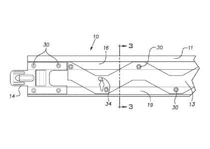
A grid runner 10, illustrated in FIGS. 1 - 3, is used in
a conventional manner to construct a rectangular grid for a
suspended ceiling. The illustrated grid runner 10 has the
shape of an inverted tee in the orientation it is used. The
grid runner 10, which typically can have a height in the order
of 1-9/16 in. can be provided as a main runner and have a
nominal length of 12 ft. The runner 10 is an assembly of
three main elongated parts comprising an upper hollow
CA 02875785 2014-12-04
WO 2013/188204 3
PCT/US2013/044459
reinforcing bulb 11, a lower face flange 12, and a vertical
web 13 extending between the bulb 11 and flange 12. Identical
end connectors 14 are provided on each end of the runner 10
(only one end is shown in FIG. 1). The connectors 14 may, for
example, be of the type illustrated in U.S. Patent 6,729,100.
Preferably, the bulb 11 and flange 12 are each made by
roll forming a single sheet metal strip, usually steel, with
conventional techniques well known in the industry. The
flange 12 can be pre-painted prior to roll forming on a side
visible when installed. The bulb is hollow with a circular
cross section. The bulb 11 can be formed with various other
cross sectional shapes such as an oval, rectangle, triangle or
other polygon. The bulb 11 is preferably formed with the
hollow space essentially closed. The bulb 11 includes a
depending rib 16 that lies in a vertical plane bisecting the
hollow part, the latter comprising the bulb proper.
The illustrated flange 12 has the shape of an inverted
short tee. In use, the flange commonly becomes the visible
face of the grid runner 10 where the grid runner is used with
ceiling tiles. A horizontal part 18 of the flange 12 extends
widthwise, i.e. transversely to the longitudinal direction of
the runner and symmetrically about a vertical upstanding stem
or rib 19. One side 21 of the horizontal flange part 18 is a
double wall or two ply construction while an opposite side 22
is a single wall with a folded back hem 23 at an edge distal
from the rib 19. In ordinary use of the runner 10 in a
suspended ceiling, edges of rectangular ceiling panels or
tiles rest on upper surfaces of the flange horizontal part 18.
The web 13 is a flat sheet metal stamping that serves to
hold the bulb 11 and flange 12 in spaced relation in the
manner of a parallel chord truss. Referring to FIG. 4, the
web 13 is formed by shearing a strip from a sheet of steel or
other metal 25, typically from coil stock. The web strip is
sheared along a serpentine line symmetrical with a line that
CA 02875785 2014-12-04
WO 2013/188204 4 PCT/US2013/044459
is perpendicular to the feed direction of the sheet stock
indicated by the arrows 26 from the supply coil.
Alternatively, the serpentine strip or web can be sheared from
a flat non-coiled sheet stock although this will involve
greater scrap due to cuts at the end of the sheet stock. The
serpentine cut profile of the web 13 is cut such that its top
and bottom edges have the same geometry. This results from
the sheared edge remaining on the stock supply becoming one of
the edges of the next sheared web piece.
In profile, the web 13 can be described as having crests
31 and valleys 32 that, in the illustrated case, are flat at
their respective top and bottom edges. The serpentine pattern
of the web 13 allows the web to span, from the outside edges
of the valleys 32 to the outside edges of the crests 31 a
distance of 1-3/8 in., for example, while the stock need only
be fed 3/4 in., for example, to produce this span. When
assembled, the web crest flats and valley flats can abut the
bottom of the bulb 11 and top of the single ply flange side
22, respectively.
The grid runner 10 is assembled in a press of a length
adequate to span the length of the grid runner. The disclosed
grid runner construction is ideally suited for main runners
which are nominally 12 ft. long or industry metric equivalent.
When the runner 10 is this long, it is practical to use 2 or 3
web sections 33 arranged end to end. Making the full length
web 13 from the sub-parts or sections 33 enables the use of
light gauge coil stock of a conventional width. Preferably,
the web sections 33 are slightly overlapped at their adjacent
ends when assembled into a grid runner 10. FIG. 5 illustrates
three web sections 33 with their adjacent ends aligned to be
overlapped and joined in a single main runner 10.
With reference to FIG. 1, the web 13 is fixed to the bulb
11 and flange 12 in a press. The web crests 31 are fixed to
the bulb rib 16 and the valleys 32 are fixed to the flange rib
CA 02875785 2014-12-04
WO 2013/188204 5
PCT/US2013/044459
19. FIG. 6 illustrates a typical permanent clinch joint 30
made by a known technique such as that marketed under the
trademark TOM (a registered trademark of Pressotechnik GmbH &
Co. KG). The technique involves lapping these members and
driving a part of the web into respective parts of the bulb
and flange ribs 16, 19. The same clinch location can be used
to join the overlapped ends of the web sections 33 to a bulb
rib or a flange rib. Cross tee slots 34 are preferably
punched from the side of the runners from which the web 13 is
assembled to simplify this punching operation. Hanger holes,
not shown, can be punched in the bulb rib 16 and any overlying
portion of the web 13 during the press operation. The end
connectors 14 are metal plates assembled on the ends of the
bulb 11 and flange 12, preferably with the clinch shown in
FIG. 6. The end connectors 14 can be of the general type
shown, for example, in U.S. Patent 6,729,100.
It is envisioned that a material savings up to about 30%
can be obtained with the serpentine web 13 as compared to
constructions having a conventional web with no large open
areas. While the foregoing disclosure involves a main runner
or main tee, the serpentine open web construction can be used
to construct cross runners. The flange can have different
cross sectional configurations other than the illustrated
simple tee. Such configurations can include a downwardly open
channel, sometimes referred to as a screw slot runner.
It should be evident that this disclosure is by way of
example and that various changes may be made by adding,
modifying or eliminating details without departing from the
fair scope of the teaching contained in this disclosure. The
invention is therefore not limited to particular details of
this disclosure except to the extent that the following claims
are necessarily so limited.