Sélection de la langue

Search

Sommaire du brevet 2876687 

Énoncé de désistement de responsabilité concernant l'information provenant de tiers

Une partie des informations de ce site Web a été fournie par des sources externes. Le gouvernement du Canada n'assume aucune responsabilité concernant la précision, l'actualité ou la fiabilité des informations fournies par les sources externes. Les utilisateurs qui désirent employer cette information devraient consulter directement la source des informations. Le contenu fourni par les sources externes n'est pas assujetti aux exigences sur les langues officielles, la protection des renseignements personnels et l'accessibilité.

Disponibilité de l'Abrégé et des Revendications

L'apparition de différences dans le texte et l'image des Revendications et de l'Abrégé dépend du moment auquel le document est publié. Les textes des Revendications et de l'Abrégé sont affichés :

  • lorsque la demande peut être examinée par le public;
  • lorsque le brevet est émis (délivrance).
(12) Brevet: (11) CA 2876687
(54) Titre français: MECANISME DE SERRAGE DE TUBE SPIRALE
(54) Titre anglais: CONTINUOUS OIL PIPE CLAMP MECHANISM
Statut: Octroyé
Données bibliographiques
(51) Classification internationale des brevets (CIB):
  • E21B 19/22 (2006.01)
(72) Inventeurs :
  • LIU, DONG (Chine)
  • YU, QINGFENG (Chine)
  • FANG, JILEI (Chine)
(73) Titulaires :
  • YANTAI JEREH OILFIELD SERVICES GROUP CO., LTD. (Chine)
  • YANTAI JEREH PETROLEUM EQUIPMENT & TECHNOLOGIES CO., LTD. (Chine)
(71) Demandeurs :
  • YANTAI JEREH OILFIELD SERVICES GROUP CO., LTD. (Chine)
  • YANTAI JEREH PETROLEUM EQUIPMENT & TECHNOLOGIES CO., LTD. (Chine)
(74) Agent: BERESKIN & PARR LLP/S.E.N.C.R.L.,S.R.L.
(74) Co-agent:
(45) Délivré: 2019-04-23
(86) Date de dépôt PCT: 2012-11-29
(87) Mise à la disponibilité du public: 2014-05-30
Requête d'examen: 2017-08-24
Licence disponible: S.O.
(25) Langue des documents déposés: Anglais

Traité de coopération en matière de brevets (PCT): Oui
(86) Numéro de la demande PCT: PCT/CN2012/085504
(87) Numéro de publication internationale PCT: WO2014/079085
(85) Entrée nationale: 2014-12-15

(30) Données de priorité de la demande:
Numéro de la demande Pays / territoire Date
201220621879.8 Chine 2012-11-21

Abrégés

Abrégé français

La présente invention concerne un mécanisme de serrage d'un tube spiralé comprenant un bloc de serrage en forme de selle (1) et un siège de bloc de serrage (4). Le bloc de serrage en forme de selle (1) est bouclé sur le siège de bloc de serrage (4). Le bloc de serrage en forme de selle (1) comprend une partie serrage en forme de selle et une partie inférieure. La partie inférieure est munie d'une rainure de serrage (103), et des plates-formes de languette (102) sont disposées aux deux extrémités de la rainure de serrage. Le siège de bloc de serrage (4) comprend une partie montage pour le montage du bloc de serrage en forme de selle. La partie montage est munie d'une rainure enfoncée (407) correspondant à la rainure de serrage, et est munie de paires de bossages (404). Une rainure (405) correspondant à la plate-forme de languette est formée entre chaque paire de bossages. La rainure de serrage (103) est bouclée dans la rainure enfoncée (407). Les plates-formes de languette (102) sont disposées dans la rainure (405) et limitées à l'aide de goupilles d'arrêt (2). La structure permet de démonter et de remplacer le bloc de serrage, et une tête d'injection avec le dispositif de serrage a l'avantage d'être stable dans une tâche continue et commode à entretenir.


Abrégé anglais


The continuous oil pipe clamp mechanism comprises a saddle-shaped
clamp block (1) and a clamp block seat (4), wherein, the saddle-shaped clamp
block (1) is buckled on the clamp block seat (4); the saddle-shaped clamp
block (1) comprises a saddle-shaped clamp portion and a bottom, wherein the
bottom is provided with a clamp groove (103), and tongue platforms (102) are
arranged at two ends of the clamp groove; the clamp block seat (4) comprises a

fit portion in fit with the saddle-shaped clamp block, wherein the fit portion
is
provided with a sunk groove (407) matched with the clamp groove and pairs of
bosses (404); grooves matched with the tongue platforms are formed between
the pairs of bosses; the clamp groove (103) is buckled in the sunk groove
(407),
and the tongue platforms (102) are arranged in the grooves (405) and are
limited by stop pins (2). The structure has the advantages of facilitating
replacement of the clamp block, enabling an injection head to be stable in
continuous work and convenient to maintain, and the like.

Revendications

Note : Les revendications sont présentées dans la langue officielle dans laquelle elles ont été soumises.


Claims
1. A continuous oil pipe clamp mechanism, comprising a clamp block
seat (4) and a saddle-shaped clamp block (1) buckled on the clamp block seat
(4), wherein:
the saddle-shaped clamp block (1) comprises a saddle-shaped clamp
portion and a bottom, wherein the bottom is provided with a clamp groove
(103) in a direction perpendicular to a clamped oil pipe, and tongue platforms

(102) are arranged at two ends of the clamp groove (103);
the clamp block seat (4) comprises a fit portion in fit with the bottom of
the saddle-shaped clamp block (1), wherein the fit portion is provided with a
sunk groove (407) matched with the clamp groove (103) on two edges in the
direction perpendicular to the clamped oil pipe, shoulder platforms (408) are
formed at two sides of the sunk groove (407), the fit portion is provided with
a
pair of bosses (404) corresponding to the tongue platforms (102) at two ends
of
the clamp block, and the boss (404) is arranged with a stop pin hole (403);
grooves (405) matched with the tongue platforms (102) are formed between
the pairs of bosses (404);
the clamp groove (103) is buckled in the sunk groove (407), the tongue
platforms (102) are arranged in the grooves (405), and the saddle-shaped
clamp block (1) is limited on the clamp block seat (4) by stop pins (2)
arranged
in the stop pin holes (403).
2. The continuous oil pipe clamp mechanism according to claim 1, wherein,
the length of the sunk groove (407) is greater than that of the clamp groove
(103),
and free clearance is formed between them.
8

3. The continuous oil pipe clamp mechanism according to claim 1 or 2,
wherein, a gasket (8) is arranged between the saddle-shaped clamp block (1)
and
the clamp block seat (4).
4. The continuous oil pipe clamp mechanisrn according to claim 3, wherein,
the gasket (8) has a plurality of holes (801).
5. The continuous oil pipe clamp mechanism according to claim 3, wherein,
the clamp block seat (4) further comprises a pin shaft (7) and a rolling
element (5)
fitted over the pin shaft (7); the clamp block seat (4) is arranged with two
through-holes (402) for connecting a chain of an injection head in the
direction of
the pin shaft (7), the clamp block seat (4) is arranged with three partitions
(406)
on its upper part, and pin shaft holes (401) for receiving the pin shaft (7)
are
arranged in the partitions (406).
6. The continuous oil pipe clamp mechanism according to claim 5, wherein,
the rolling element (5) is a rolling bearing or rolling bushing.
7. The continuous oil pipe clamp mechanism according to claim 6, wherein,
the pin shaft (7) is provided with a circlip for shaft (6) on each end.
8. The continuous oil pipe clamp mechanism according to claim 1 or 2,
wherein, the saddle-shaped clamp portion of the saddle-shaped clamp block (1)
is
arranged with at least two arc grooves (101).
9

Description

Note : Les descriptions sont présentées dans la langue officielle dans laquelle elles ont été soumises.

CA 02876687 2014-12-15
Description
Continuous Oil Pipe Clamp Mechanism
Field of the Invention
The present invention relates to the field of oil extraction equipment, in
particular to a continuous oil pipe clamp mechanism.
Background of the Invention
An injection head is a key component of coiled tubing equipment, and a
clamp mechanism provides clamping force for the injection head, so as to
convey
the continuous oil pipe. At present, on commonly used injection heads, a clamp
o mechanism with a rolling element is usually used, but the connection
between a
clamp block and a clamp block seat of the clamp mechanism has the following
drawbacks: first, the clamp block and clamp block seat are inconvenient to
install
or replace, since screws are used for position limiting; second, the limit
screws
may get loose or even be fractured under the frequent shearing force incurred
by
the random load on the clamp block in the clamp mechanism, and consequently
the stability of the clamp mechanism in continuous operation is affected;
third,
the free clearance of the clamp block on the clamp block seat is small owing
to
the existing fixing method, which is disadvantageous for self-adjustment of
the
clamp block when the clamp block is used to clamp an oil pipe, and
consequently
the clamp block may produce high impact on the oil pipe and result in severe
abrasion of the oil pipe.
Summary of the Invention

CA 02876687 2014-12-15
To overcome the above-mentioned drawbacks in the prior art, the present
invention provides a continuous oil pipe clamp mechanism, which can work
stably and is easy to remove and replace.
The present invention employs the following technical scheme to solve
the above-mentioned technical problems: a continuous oil pipe clamp
mechanism, comprising a clamp block seat and a saddle-shaped clamp block
buckled on the clamp block seat, wherein:
the saddle-shaped clamp block comprises a saddle-shaped clamp portion
and a bottom, wherein the bottom is provided with a clamp groove in a
direction
o perpendicular to a clamped oil pipe, and tongue platforms are arranged at
two
ends of the clamp groove;
the clamp block seat comprises a fit portion in fit with the bottom of the
saddle-shaped clamp block, wherein the fit portion is provided with a sunk
groove matched with the clamp groove on two edges in the direction
perpendicular to the clamped oil pipe, shoulder platforms are formed at two
sides of the sunk groove, the fit portion is provided with a pair of bosses
corresponding to the tongue platforms at two ends of the clamp block, and the
boss is arranged with a stop pin hole; grooves matched with the tongue
platforms are formed between the pairs of bosses;
the clamp groove is buckled in the sunk groove, the tongue platforms are
arranged in the grooves, and the saddle-shaped clamp block is limited on the
clamp block seat by stop pins arranged in the stop pin holes.
The beneficial effects of the present invention include: the should platforms
on the clamp block seat limits the length of movement of the saddle-shaped
clamp block in the moving direction of the oil pipe; since the saddle-shaped
2

CA 02876687 2014-12-15
clamp block is pressed on the clamp block seat by stop pins, the saddle-shaped

clamp block is convenient and easy to install and replace, and is more
reliable to
use.
On the basis of the technical scheme described above, the present invention
can be further improved as follows:
Furthermore, the length of the sunk groove is greater than that of the clamp
groove, and free clearance is formed between them.
The improved scheme described above has the following beneficial effects:
with appropriate free clearance arranged between the sunk groove and the clamp
groove, the clamp mechanism can work normally, and the clamp block can utilize
the free clearance to adjust its position automatically in case the continuous
oil
pipe is deformed or abraded, so that the squeeze pressure of the clamp block
on
the oil pipe can be reduced, and thereby rapid wear of the oil pipe can be
avoided.
Furthermore, a gasket is arranged between the saddle-shaped clamp block
and the clamp block seat.
The gasket has a plurality of holes.
The improved scheme described above has the following beneficial effect:
the elastic gasket can effectively buffer the radial impact produced by the
clamp
block on the oil pipe; therefore, the wearing between the oil pipe and the
clamp
block can be alleviated, and the service life of the oil pipe and clamp
mechanism
can be prolonged.
Furthermore, the clamp block seat comprises a pin shaft and a rolling
element fitted over the pin shaft; the clamp block seat is arranged with two
through-holes in the direction of the pin shaft for connecting the chain of an

injection head; the clamp block seat has three partitions on its upper part,
and
3

CA 02876687 2014-12-15
through-holes for receiving the pin shaft are arranged in the partitions.
The rolling element is a rolling bearing or rolling bushing.
The improved scheme described above has the following beneficial effect:
with a rolling bearing or rolling bushing, the clamp mechanism can move more
smoothly.
Furthermore, a circlip for shaft is arranged on each end of the pin shaft.
The improved scheme described above has the following beneficial effect:
the rolling element can be removed and replaced quickly.
Furthermore, the saddle-shaped clamp portion of the saddle-shaped clamp
block is arranged with at least two arc grooves.
The improved scheme described above has the following beneficial effect:
with the arc grooves, the clamping force on the continuous oil pipe can be
increased, and potential damage to the oil pipe resulted from foreign matters
can
be avoided.
Brief Description of the Drawings
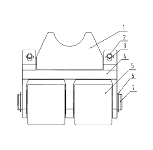
Fig.1 is a schematic structural diagram of the continuous oil pipe clamp
mechanism according to the present invention;
Fig.2 is a side view of the structure shown in Fig.1;
Fig.3 is a front view of the saddle-shaped clamp block of the continuous oil
pipe clamp mechanism according to the present invention;
Fig.4 is a side view of the structure shown in Fig.3;
Fig.5 is a side view of the clamp block seat of the continuous oil pipe clamp
mechanism (without rolling element) according to the present invention;
Fig.6 is a front view of the structure shown in Fig.5;
4

CA 02876687 2014-12-15
Fig.7 is a bottom view of the structure shown in Fig.5;
Fig.8 is a schematic structural diagram of the gasket of the continuous oil
pipe clamp mechanism according to the present invention.
Among Fig.1¨Fig.8, the components denoted by the symbols are: 1 -
saddle-shaped clamp block; 2 - stop pin; 3 - pin; 4 - clamp block seat; 5 -
rolling
element; 6 - circlip for shaft; 7 - pin shaft; 101 - arc groove; 102 - tongue
platform; 103 - clamp groove; 401 - pin shaft hole; 402 - through-hole; 403 -
stop
pin hole; 404 - boss; 405 - groove; 406 - partition; 407 - sunk groove; 408 -
shoulder platform; 8 - gasket; 801 - hole.
Detailed Description of the Embodiments
Hereunder the principle and characteristics of the present invention will be
detailed with reference to the accompanying drawings. However, it should be
noted that the embodiments are provided only to interpret the present
invention
but don't constitute any limitation to the scope of the present invention.
As shown in Fig.1¨Fig.8, the present invention provides a continuous oil
pipe clamp mechanism, comprising a saddle-shaped clamp block 1 and a
clamp block seat 4, wherein the saddle-shaped clamp block 1 is buckled on the
clamp block seat 4, the saddle-shaped clamp block 1 comprises a
saddle-shaped clamp portion and a bottom, wherein the bottom is provided
with a clamp groove 103 in a direction perpendicular to the clamped oil pipe,
and tongue platforms 102 are arranged at two ends of the clamp groove;
the clamp block seat 4 comprises a fit portion in fit with the bottom of the
saddle-shaped clamp block 1, wherein the fit portion is provided with a sunk
groove 407 matched with the clamp groove 103 on two edges in the direction
perpendicular to the clamped oil pipe, shoulder platforms 408 are formed at
5

CA 02876687 2014-12-15
two sides of the sunk groove 407, the fit portion is provided with a pair of
bosses 404 corresponding to the tongue platforms 102 at two ends of the clamp
block, and the boss 404 is arranged with a stop pin hole 403; grooves 405
matched with the tongue platforms 102 are formed between the pairs of bosses
404;
the clamp groove 103 is buckled in the sunk groove 407, the tongue
platforms 102 are arranged in the grooves 405, and the saddle-shaped clamp
block 1 is limited on the clamp block seat 4 by stop pins 2 arranged in the
stop
pin holes 403; pins 3 are arranged on two ends of the stop pin 2, to prevent
the
stop pin 2 from sliding off.
The length of the sunk groove 407 is greater than that of the clamp groove
103, and free clearance is formed between them.
A gasket 8 is arranged between the saddle-shaped clamp block 1 and the
clamp block seat 4.
The gasket 8 has a plurality of holes 801.
The clamp block seat 4 comprises a pin shaft 7 and a rolling element 5 fitted
over the pin shaft 7; the clamp block seat is arranged with two through-holes
402
in the direction of the pin shaft 7 for connecting the chain of an injection
head;
the main body of the clamp block seat has three partitions 406 on its upper
part,
and pin shaft holes 401 for receiving the pin shaft 7 are arranged in the
partitions
406.
The rolling element 5 is a rolling bearing or rolling bushing.
A circlip for shaft 6 is arranged on each end of the pin shaft 7.
The saddle-shaped clamp portion of the saddle-shaped clamp block 1 is
arranged with at least two arc grooves 101.
6

=
CA 02876687 2014-12-15
While the present invention is described above in some preferred
embodiments, the present invention is not limited to those preferred
embodiments.
Any modification, equivalent replacement, and improvement made without
departing from the spirit and principle of the present invention shall be
deemed as
falling into the protected domain of the present invention.
7

Dessin représentatif
Une figure unique qui représente un dessin illustrant l'invention.
États administratifs

Pour une meilleure compréhension de l'état de la demande ou brevet qui figure sur cette page, la rubrique Mise en garde , et les descriptions de Brevet , États administratifs , Taxes périodiques et Historique des paiements devraient être consultées.

États administratifs

Titre Date
Date de délivrance prévu 2019-04-23
(86) Date de dépôt PCT 2012-11-29
(87) Date de publication PCT 2014-05-30
(85) Entrée nationale 2014-12-15
Requête d'examen 2017-08-24
(45) Délivré 2019-04-23

Historique d'abandonnement

Il n'y a pas d'historique d'abandonnement

Taxes périodiques

Dernier paiement au montant de 263,14 $ a été reçu le 2023-11-21


 Montants des taxes pour le maintien en état à venir

Description Date Montant
Prochain paiement si taxe générale 2024-11-29 347,00 $
Prochain paiement si taxe applicable aux petites entités 2024-11-29 125,00 $

Avis : Si le paiement en totalité n'a pas été reçu au plus tard à la date indiquée, une taxe supplémentaire peut être imposée, soit une des taxes suivantes :

  • taxe de rétablissement ;
  • taxe pour paiement en souffrance ; ou
  • taxe additionnelle pour le renversement d'une péremption réputée.

Les taxes sur les brevets sont ajustées au 1er janvier de chaque année. Les montants ci-dessus sont les montants actuels s'ils sont reçus au plus tard le 31 décembre de l'année en cours.
Veuillez vous référer à la page web des taxes sur les brevets de l'OPIC pour voir tous les montants actuels des taxes.

Historique des paiements

Type de taxes Anniversaire Échéance Montant payé Date payée
Le dépôt d'une demande de brevet 400,00 $ 2014-12-15
Taxe de maintien en état - Demande - nouvelle loi 2 2014-12-01 100,00 $ 2014-12-15
Taxe de maintien en état - Demande - nouvelle loi 3 2015-11-30 100,00 $ 2015-10-05
Taxe de maintien en état - Demande - nouvelle loi 4 2016-11-29 100,00 $ 2016-08-25
Requête d'examen 800,00 $ 2017-08-24
Taxe de maintien en état - Demande - nouvelle loi 5 2017-11-29 200,00 $ 2017-10-23
Taxe de maintien en état - Demande - nouvelle loi 6 2018-11-29 200,00 $ 2018-08-27
Taxe finale 300,00 $ 2019-03-01
Taxe de maintien en état - brevet - nouvelle loi 7 2019-11-29 200,00 $ 2019-10-22
Taxe de maintien en état - brevet - nouvelle loi 8 2020-11-30 200,00 $ 2020-11-16
Taxe de maintien en état - brevet - nouvelle loi 9 2021-11-29 204,00 $ 2021-11-15
Taxe de maintien en état - brevet - nouvelle loi 10 2022-11-29 254,49 $ 2022-11-21
Taxe de maintien en état - brevet - nouvelle loi 11 2023-11-29 263,14 $ 2023-11-21
Titulaires au dossier

Les titulaires actuels et antérieures au dossier sont affichés en ordre alphabétique.

Titulaires actuels au dossier
YANTAI JEREH OILFIELD SERVICES GROUP CO., LTD.
YANTAI JEREH PETROLEUM EQUIPMENT & TECHNOLOGIES CO., LTD.
Titulaires antérieures au dossier
S.O.
Les propriétaires antérieurs qui ne figurent pas dans la liste des « Propriétaires au dossier » apparaîtront dans d'autres documents au dossier.
Documents

Pour visionner les fichiers sélectionnés, entrer le code reCAPTCHA :


Pour visualiser une image, cliquer sur un lien dans la colonne description du document. Pour télécharger l'image (les images), cliquer l'une ou plusieurs cases à cocher dans la première colonne et ensuite cliquer sur le bouton "Télécharger sélection en format PDF (archive Zip)" ou le bouton "Télécharger sélection (en un fichier PDF fusionné)".

Liste des documents de brevet publiés et non publiés sur la BDBC .

Si vous avez des difficultés à accéder au contenu, veuillez communiquer avec le Centre de services à la clientèle au 1-866-997-1936, ou envoyer un courriel au Centre de service à la clientèle de l'OPIC.


Description du
Document 
Date
(yyyy-mm-dd) 
Nombre de pages   Taille de l'image (Ko) 
Abrégé 2014-12-15 1 28
Revendications 2014-12-15 2 72
Dessins 2014-12-15 5 47
Description 2014-12-15 7 252
Dessins représentatifs 2014-12-15 1 4
Page couverture 2015-02-10 1 45
Requête d'examen 2017-08-24 1 43
Paiement de taxe périodique 2017-10-23 1 33
Demande d'examen 2018-07-18 4 200
Modification 2018-10-10 9 216
Revendications 2018-10-10 2 72
Abrégé 2018-10-10 1 28
Dessins 2018-10-10 4 43
Abrégé 2019-01-24 1 28
Taxe finale 2019-03-01 2 73
Dessins représentatifs 2019-03-27 1 5
Page couverture 2019-03-27 1 43
PCT 2014-12-15 6 230
Cession 2014-12-15 5 148