Note : Les descriptions sont présentées dans la langue officielle dans laquelle elles ont été soumises.
FLUID HOSE APPARATUS WITH INTEGRATED NOZZLE AND RELATED
SYSTEMS AND METHODS
CROSS REFERENCE TO RELATED APPLICATION
This application claims benefit of U.S. Provisional Application Serial No.
61/996,863, entitled, "A Low Profile Spray Nozzle for a Hose" filed May 16,
2014 and U.S.
Provisional Application Serial No. 61/998,041 entitled "A Low Profile Spray
Nozzle for a Hose"
filed June 17, 2014.
FIELD OF THE DISCLOSURE
The present disclosure is generally related to hose nozzles and more
particularly is related
to a fluid hose apparatus with integrated nozzle and related systems and
methods.
BACKGROUND OF THE DISCLOSURE
Firefighters use hoses to spray water, or other fluids, onto fires in order to
extinguish the
fires. The water exits these hoses from a nozzle at the end of the hoses,
which the firefighters can
direct to an appropriate location. Non-structural fires, such wildfires,
bushfires, or grassfires,
commonly have a wide front which is difficult to fight with conventional
hoses. Fire fighters on
the ground, or on fire trucks, can spray water onto only a small section of a
wide area fire at any
given moment, which may allow fires in other areas to increase. Sometimes,
fire trucks can
become surrounded and trapped by a fast moving fire.
One method of stopping a grassfire or a wildfire is to create a fire break, a
gap in
vegetation or other combustible material that acts as a barrier to slow or
stop the progress of a
bushfire or wildfire. Fire breaks often have a size in the range of 10 feet
wide and as long as
deemed necessary, usually sufficiently long to prevent the fire from moving
around the fire
CA 2891833 2018-03-16
break. Most fire breaks are created by teams of firefighters with hand tools,
which is highly labor
intensive. Where possible, tractors and plows can be used to create the fire
breaks, but many
wildfire locations are not easily accessible. Furthermore, when using fire
breaks, wildfires can
quickly become large and difficult to control. Large fires create winds that
blow burning embers
through the air over long distances. A 10 foot fire break can be easily jumped
by blowing
embers, which subverts the intended purpose of the fire break.
Within the industry, some conventional devices are available to help prevent
blowing
embers moving past a fire break. One such device, called a water curtain, uses
a conventional
hose that has many simple holes that are placed close together along the
length of the hose. As
water is pumped through the hose, it exits each hole and is directed straight
up in a vertical
column. The resulting overall spray shape is that of a thin curtain, in that,
the spraying water is
positioned along the length of the hose, but it is only a very thin wall of
water. These water
curtains are rarely used because they are too thin to significantly reduce
radiant heat from a fire,
and because the available water is better used to wet the nearby fuels to
prevent their ignition.
One technique to protect a structure, such as a building, from a wildfire is
to deploy a
defensive line of rotating sprinklers on tripods, and to supply these
sprinklers with water using
fire hoses. Setting up such a system can be very time consuming, and the
hardware required is
expensive. Another technique to protect a structure is to place permanent
sprinklers on the roofs
or walls of the structures. This technique, unfortunately, allows the fire to
get very close to the
structure before encountering a spray of water or other fire resisting fluids,
which subjects the
structure to high temperatures from the encroaching fire. The radiant heat
from a fire can be very
intense and it is best to keep the fire farther away from the structure.
Placing sprinklers on the
2
CA 2891833 2018-03-16
structure is not as effective as having a system located farther from the
structure which can spray
fluid to stop a wildfire.
Thus, a heretofore unaddressed need exists in the industry to address the
aforementioned
deficiencies and inadequacies.
SUMMARY OF THE DISCLOSURE
Embodiments of the present disclosure provide a fluid hose apparatus with
integrated
nozzle. Briefly described, in architecture, one embodiment of the apparatus,
among others, can
be implemented as follows. A hose has at least one sidewall hole formed within
a sidewall
thereof. At least one patch is affixed to the sidewall of the hose, the at
least one patch positioned
over the at least one sidewall hole. A chamber is formed between the at least
one patch and the
sidewall of the hose, wherein the chamber is in fluid communication with the
at least one
sidewall hole. At least two nozzles is formed in an exterior wall of the at
least one patch, wherein
the at least two nozzles is in fluid communication with the chamber.
The present disclosure can also be viewed as providing a supply line system
for
conveying and spraying a fluid. Briefly described, in architecture, one
embodiment of the
system, among others, can be implemented as follows. An elongated hose has a
plurality of
sidewall holes formed within a sidewall thereof and positioned at spaced
intervals along a length
of the hose. The elongated hose carries a quantity of pressurized fluid. A
plurality of patches is
affixed to the sidewall of the hose. Each of the patches is positioned over at
least one of the
plurality of sidewall holes. A chamber is formed between each of the plurality
of patches and the
sidewall of the hose, wherein each chamber is in fluid communication with at
least one of the
plurality of sidewall holes. At least two nozzles is formed in an exterior
wall of each of the
3
CA 2891833 2018-03-16
plurality of patches, wherein the at least two nozzles is in fluid
communication with the chamber
of each of the plurality of patches, wherein a portion of the quantity of
pressurized fluid is
expelled from each of the at least two nozzles.
The present disclosure can also be viewed as providing a method of protecting
an
elongated hose from a heat source. In this regard, one embodiment of such a
method, among
others, can be broadly summarized by the following steps: transporting a
quantity of pressurized
fluid through a hose; directing a portion of the quantity of pressurized fluid
through at least one
sidewall hole formed within a sidewall of the hose; dispersing a directional
path of the portion of
the quantity of pressurized fluid within a chamber, wherein the chamber is
formed between at
least one patch and the sidewall of the hose; dispersing the portion of the
quantity of pressurized
fluid through at least two nozzles formed in an exterior wall of the at least
one patch.
Other systems, methods, features, and advantages of the present disclosure
will be or
become apparent to one with skill in the art upon examination of the following
drawings and
detailed description. It is intended that all such additional systems,
methods, features, and
advantages be included within this description, be within the scope of the
present disclosure, and
be protected by the accompanying claims.
BRIEF DESCRIPTION OF THE DRAWINGS
Many aspects of the disclosure can be better understood with reference to the
following
drawings. The components in the drawings are not necessarily to scale,
emphasis instead being
placed upon clearly illustrating the principles of the present disclosure.
Moreover, in the
drawings, like reference numerals designate corresponding parts throughout the
several views.
4
CA 2891833 2018-03-16
FIG. 1 is an isometric view illustration of a fluid hose apparatus with
integrated nozzle, in
accordance with a first exemplary embodiment of the present disclosure.
FIG. 2 is an exploded, side cross-sectional view illustration of the fluid
hose apparatus
with integrated nozzle of FIG. 1, in accordance with the first exemplary
embodiment of the
present disclosure.
FIG. 3 is a side cross-sectional view illustration of fluid paths within the
fluid hose
apparatus with integrated nozzle of FIG. 1, in accordance with the first
exemplary embodiment
of the present disclosure.
FIG. 4 is a front cross-sectional view illustration of fluid paths within the
fluid hose
apparatus with integrated nozzle of FIG. 1, in accordance with the first
exemplary embodiment
of the present disclosure.
FIG. 5 is an isometric view illustration of the fluid hose apparatus with
integrated nozzle,
in accordance with the first exemplary embodiment of the present disclosure.
FIG. 6 is an isometric view illustration of a fluid hose apparatus with
integrated nozzle, in
accordance with the first exemplary embodiment of the present disclosure.
FIG. 7 is a side view illustration of the fluid hose apparatus with integrated
nozzle of
FIG. 1 having a round hose, in accordance with the first exemplary embodiment
of the present
disclosure.
FIG. 8 is a side view illustration of the fluid hose apparatus with integrated
nozzle of
FIG. 1 having a lay-flat hose without pressurized fluid, in accordance with
the first exemplary
embodiment of the present disclosure.
5
CA 2891833 2018-03-16
FIG. 9 is a side view illustration of the fluid hose apparatus with integrated
nozzle having
a lay-flat hose of FIG. 8 with pressurized fluid, in accordance with the first
exemplary
embodiment of the present disclosure.
FIGS. 10A-10C are schematic illustrations of the fluid hose apparatus with
integrated
nozzle of FIG. 1 showing various nozzle positions, in accordance with the
first exemplary
embodiment of the present disclosure.
FIG. Ibis a partially exploded side view illustration of the fluid hose
apparatus with
integrated nozzle of FIG. 1 with a binding strap, in accordance with the first
exemplary
embodiment of the present disclosure.
FIG. 12 is an isometric view illustration of the locking device of the binding
strap, in
accordance with the first exemplary embodiment of the present disclosure.
FIG. 13 is a side view illustration of the fluid hose apparatus with
integrated nozzle in use
with a binding strap and a positioning device, in accordance with the first
exemplary
embodiment of the present disclosure.
FIG. 14 is a flowchart illustrating a method of protecting an elongated hose
from a heat
source, in accordance with the first exemplary embodiment of the disclosure.
DETAILED DESCRIPTION
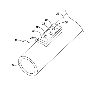
FIG. 1 is an isometric view illustration of a fluid hose apparatus with
integrated nozzle
10, in accordance with a first exemplary embodiment of the present disclosure.
FIG. 2 is an
exploded, side cross-sectional view illustration of the fluid hose apparatus
with integrated nozzle
10 of FIG. 1, in accordance with the first exemplary embodiment of the present
disclosure. FIG. 3
is a side cross-sectional view illustration of fluid paths within the fluid
hose apparatus with
6
CA 2891833 2018-03-16
integrated nozzle 10 of FIG. 1, in accordance with the first exemplary
embodiment of the present
disclosure. FIG. 4 is a front cross-sectional view illustration of fluid paths
within the fluid hose
apparatus with integrated nozzle 10 of FIG. 1, in accordance with the first
exemplary
embodiment of the present disclosure. With reference to FIGS. 1-4, the fluid
hose apparatus with
integrated nozzle 10, which may be referred to herein simply as 'apparatus
10', includes a hose
20 having at least one sidewall hole 22 formed within a sidewall 24 thereof.
At least one patch
30 is affixed to the sidewall 24 of the hose 20 and positioned over the at
least one sidewall hole
22. A chamber 40 is formed between the at least one patch 30 and the sidewall
24 of the hose 20.
The chamber 40 is in fluid communication with the at least one sidewall hole
22. At least two
nozzles 50 is formed in an exterior wall 32 of the at least one patch 30,
wherein the at least two
nozzles 50 is in fluid communication with the chamber 40.
The apparatus 10 may provide significant benefits in fluid transportation
through hoses
which are located in environments prone to damaging the hoses. As a primary
example herein,
the apparatus 10 may provide significant benefits in fighting non-structural
fires, such as
wildfires, forest fires, bushfires, grassfires, or other fires which require
hoses to be located in
settings where the radiant heat from the fire can damage the hose. The hose 20
may include a
fluid pipe or conduit which is capable of carrying fluid under pressure. The
fluid may include
water or other fire resistant fluids, such as flame retardant chemicals. The
hose 20 may have any
length or diameter, and may be constructed from a variety of materials
conventionally used
within the industry.
The hose 20 has at least one sidewall hole 22 formed within a sidewall 24
thereof.
Commonly, a plurality of sidewall holes 22 may be formed within the sidewall
24 of the hose 20
along its length, or a portion of its length. The size of the sidewall hole 22
may vary depending
7
CA 2891833 2018-03-16
on the size of the hose 20 and/or an intended design of the apparatus 10, such
as to provide for a
desired flow rate of the fluid through the apparatus 10. The sidewall hole 22
may further include
a grommet or similar structure to maintain a shape or size of the sidewall
hole 22 within the
sidewall 24, e.g., to prevent tearing, stretching, or fraying of the hose
material surrounding the
sidewall hole 22.
The at least one patch 30 may be an attachment to the hose 20 which is
substantially
integrated into the general shape of the hose 20. The patch 30 may commonly
include a plurality
of patches 30 which are overlaid on one another to create a compounded patch.
As is shown in
FIGS. 1-4, two patches 30 are used, where an interior of a lower patch
substantially forms the
chamber 40 and the at least two nozzles 50 is formed in an upper patch
overlaying the lower
patch. The patch 30 may be affixed to an exterior surface of the sidewall 24
of the hose 20 with a
variety of connections, such as with using adhesives, chemical bonds, material
welds or fusing,
mechanical fasteners, or other devices which can create a fluid-tight
connection. The patch 30 is
positioned on the hose 20 in a location overlying the at least one sidewall
hole 22.
Interior of the patch 30, the chamber 40 is in fluid communication with the
sidewall hole
22 to allow fluid within the hose 20 to exit an interior of the hose 20
through the sidewall hole 22
and enter the chamber 40. The chamber 40 may be formed between the patch 30 or
patches and
the exterior surface of the sidewall 24 of the hose 20. The chamber 40 may be
defined as an
interior cavity or space of the patch 30 which abuts the sidewall hole 22.
When two patches 30
are used, as is shown, the chamber 40 may be formed by removing a segment from
an interior
volume of a lower patch. Commonly, the chamber 40 may be formed between
interior sidewalls
34, a ceiling 36, and the exterior surface of the hose 20 (or an interfacing
material which is
8
CA 2891833 2018-03-16
affixed to an exterior surface of the hose 20). The specific dimension of the
chamber 40 may
vary, which may be dependent on the size of the patch 30.
The at least two nozzles 50 may commonly include two or more nozzles 50 within
each
patch 30. The nozzle 50 may be characterized as an opening within the patch 30
that allows the
fluid within the chamber 40 to be expelled into a surrounding environment. The
nozzles 50 may
include the use of a grommet, a spout, or a similar structure to maintain a
shape or size of the
nozzles 50 within the patch 30, or to assist with directing the flow of fluid
through the nozzles 50.
The nozzles 50 may be formed in an exterior wall 32 of the patch 30 or
patches, such that it is in
fluid communication with the chamber 40.
The presence of the chamber 40 within the fluid path through the apparatus 10
(identified
by arrows 60 in FIGS. 3-4), may be important in controlling the fluid spray
path external of the
apparatus 10 (identified by arrows 62 in FIGS. 3-4). While a single hole
within the hose 20 may
allow fluid therein to exit the hose 20, the flow of the fluid through the
single hole alone may be
largely unidirectional, bidirectional at best. In other words, the fluid
exiting the single hole
would have the shape of a narrow stream before falling to the ground outside
of the hose 20. The
use of the chamber 40 forces the fluid within the hose 20 to experience a
turbulent fluid path 60
through the apparatus 10 prior to exiting. This turbulent or disruptive fluid
path 60 may create a
complex flow of the fluid, which allows the fluid to exit the nozzles 50 with
a wide stream prior
to falling to the ground. As shown in FIGS. 3-4, the fluid path 60 within the
apparatus 10 may
include fluid exiting the sidewall hole 22 and being forced to move laterally
within the chamber
40. The fluid may repeatedly contact the interior sidewalls 34 of the chamber
40, the ceiling 36
of the chamber 40, and the abutting portion of exterior surface of the hose 20
sidewall 24 before
being expelled from the nozzles 50. These complex flow patterns will cause the
fluid spray path
9
CA 2891833 2018-03-16
62 external of the apparatus 10 to be a multidirectional, three-dimensional,
wide area spray
pattern, which can significantly aid in protecting the hose 20 from radiant
heat of an encroaching
fire. Such a spray pattern is useful for creating a fire break that can be
used to protect structures
and infrastructure from fires.
The turbulent and disruptive fluid path 60 within the apparatus 10 may be
controlled by a
variety of design specifications of the apparatus 10, including the size of
the chamber 40, the
positioning of the chamber 40 relative to the sidewall hole 22, the
positioning of the nozzle(s) 50
relative to the sidewall hole 22, or others. For example, the nozzles 50 may
be axially misaligned
with the at least one sidewall hole 22, such that a central axis of the
nozzles 50 is misaligned with
a central axis of the sidewall hole 22, thereby preventing fluid from flowing
in a unidirectional
path through both the sidewall hole 22 and nozzles 50. In another example, a
cross-sectional
footprint of the nozzles 50 may be non-overlapping a cross-sectional footprint
of the sidewall
hole 22, such that there is no cross-sectional area of either the sidewall
hole 22 or nozzle 50 that
is positioned overlapping. The sidewalls 34 of the chamber 40 may also be
positioned a spaced
distance from the nozzles 50, such that a sidewall of the nozzles 50 is not
aligned with a sidewall
34 of the chamber 40. This positioning may force the fluid path 60 to move
past the nozzles 50,
contact the sidewall 34, and move back towards a middle of the chamber 40, and
so forth, before
being expelled from the nozzles 50.
It is noted that the apparatus 10 may be sized to be a low-profile structure,
such that it
does not interfere with normal usage of the hose 20, such as when the hose 20
is spooled on a
reel or folded into a storage compartment of a fire truck. If the multiplicity
of patches 30,
chambers 40, and nozzles 50 formed along the length of the hose 20 were not
low-profile, but had
significant protrusions, the hose 20 may be hindered from smoothly deploying
from a reel or
CA 2891833 2018-03-16
a folded geometry. The significant protrusions could create snags and tangles
in the hose 20
which could prevent proper hose 20 deployment. Additionally, the hose 20 and
the patch 30 may
be constructed from flexible materials which allow reeling or folding of the
apparatus 10 easily.
In one example, the patch 30 material may be constructed from the same
material as the flexible
hose 20. The overall height of the apparatus 10 from the exterior surface of
the hose 20 may
vary, depending on the design.
FIG. 5 is an isometric view illustration of the fluid hose apparatus with
integrated nozzle
10, in accordance with the first exemplary embodiment of the present
disclosure. The structure of
the apparatus 10 as described in FIGS. 1-4 may be applied along a length of
hose 20 at spaced
intervals. The apparatus 10 includes a plurality of sidewall holes formed
within the sidewall 24
of the hose 20 and positioned at spaced intervals along the length of the hose
20. A plurality of
patches 30 are affixed to the sidewall 24 of the hose 20 at spaced intervals,
corresponding to the
spaced intervals of the sidewall holes, such that each of the plurality of
patches 30 is positioned
over at least one of the plurality of sidewall holes. Each patch 30 has the
chamber formed therein
and each of the plurality of patches 30 has the at least one nozzle formed in
the exterior wall
thereof. The patches 30 are placed at spatial intervals to produce a spray
that supplies a desired
flow pattern along the length of the hose 20.
FIG. 6 is an isometric view illustration of a fluid hose apparatus with
integrated nozzle
10, in accordance with the first exemplary embodiment of the present
disclosure. The apparatus
of FIG. 6 includes nozzles 50 that are positioned on both an upper exterior
wall 32 or ceiling of
the patch 30 and a sidewall of the patch 30 on both a side and front of the
patch 30. The use of
nozzles 50 on various sides of the patch 30 may allow for an increased fluid
spray path
surrounding the hose 20. Each of the nozzles 50 may be in fluid communication
with the
11
CA 2891833 2018-03-16
chamber 40 which is in fluid communication with the sidewall hole 22
positioned in the sidewall
24 of the hose 20. It is noted that the nozzles 50 may be positioned on the
patch 30 in a variety of
locations, including any of the sidewalls or any location within the exterior
wall 32.
FIG. 7 is a side view illustration of the fluid hose apparatus with integrated
nozzle 10 of
FIG. 1 having a round hose 20, in accordance with the first exemplary
embodiment of the present
disclosure. FIG. 8 is a side view illustration of the fluid hose apparatus
with integrated nozzle 10
of FIG. 1 having a lay-flat hose 20 without pressurized fluid, in accordance
with the first
exemplary embodiment of the present disclosure. FIG. 9 is a side view
illustration of the fluid
hose apparatus with integrated nozzle 10 having a lay-flat hose 20 of FIG. 8
with pressurized
fluid, in accordance with the first exemplary embodiment of the present
disclosure. With
reference to FIGS. 7-9, the hose 20 may include many types of hoses having a
variety of shapes.
For example, FIG. 7 illustrates the hose 20 as a round hose which always
maintains a round
cross-sectional shape. FIG. 8 illustrates a hose 20 with a lay-flat design,
where the hose 20
assumes a thin oval shape when there is no pressurized fluid inside it. The
lay-flat design allows
a greater length of hose 20 to be stored in a given volume than would be the
case for a hose 20
that always has a round shape. When a sufficient pressure is applied to fluid
in the lay-flat design
of the hose 20, the hose 20 assumes a round shape, as is shown in FIG. 9. Each
of the hoses 20 in
FIGS. 7-9 is illustrated with the patch 30 with nozzle positioned on the hose
20. The angular
orientation of the patch 30 with nozzle in FIGS. 7 and 9 may be controlled
when the hose 20 is
deployed onto the ground, as discussed further herein.
FIGS. 10A-10C are schematic illustrations of the fluid hose apparatus with
integrated
nozzle 10 of FIG. 1 showing various nozzles 50 positions, in accordance with
the first exemplary
embodiment of the present disclosure. The angle that the water sprays from the
nozzles 50 on the
12
CA 2891833 2018-03-16
hose 20 can be varied, as expressed in the horizontal distance H and the
vertical distance V in
FIGS. 10A-10C. For example, if the angle is 45 degrees from the vertical, as
shown in FIG. 10A,
then the vertical and horizontal distances of the spray will tend to be the
same. A flatter angle
with a larger horizontal distance may give more protection to the hose 20 from
the fire. FIG. 10B
shows the angle to the ground to be much less than 45 degrees. This angle
makes H much larger
than V. A more vertical angle, as shown in FIG. 10C, with a larger vertical
height, may also be
able to stop the spread of taller fires. The angle can be changed by rotating
the hose 20 relative to
a ground surface.
FIG. 11 is a partially exploded side view illustration of the fluid hose
apparatus with
integrated nozzle 10 of FIG. 1 with a binding strap 70, in accordance with the
first exemplary
embodiment of the present disclosure. The binding strap 70 may be a structure
similar to a
bundling strap or cable tie, which encircles the hose 20 and connects with the
hose 20, such that
the hose 20 can be rotated to angle the nozzle in a specific direction, as
discussed relative to
FIGS. 10A-10C. The binding strap 70 may include a locking device 74 which is
permanently
attached to one end of the strap length and allows the other end to be
received through the
locking device 74 and retained therein. As is known in the art, the locking
device may utilize a
plurality of teeth 76 with a biasable locking pin that engages the teeth 76
inside the locking
device 74. The locking pin may be controlled with a button or similar
structure positioned on the
locking device 74.
The binding strap 70 may be connected to the exterior surface 26 of the hose
20 with a
mateable surface engagement 80 positioned between an interior surface 72 of
the binding strap
70 and the exterior surface 26 of the hose 20. The mateable surface engagement
80 may include
two mateable undulating surfaces, one positioned on the exterior surface 26 of
the hose 20 and
13
CA 2891833 2018-03-16
one positioned on the interior surface 72 of the binding strap 70. Each of the
undulating surfaces
may include a plurality of peaks 82 and valleys 84, or similar shapes, which
allow the two
structures to engage whcn positioned together, such as when the binding strap
70 is tightened
around the hose 20. When engaged, the binding strap 70 may be sufficiently
connected to the
hose 20 to allow the two structures to move in a unitary fashion, such that
rotation of the binding
strap 70 will cause the hose 20 to rotate. The undulating surface on the hose
20 may be
positioned at select locations along the hose 20 or run parallel to an entire
length of the hose 20.
Similarly, the undulating surface may be positioned at select locations
radially about the hose 20
and on select locations on the interior surface 72 of the binding strap 70,
all of which are
considered within the scope of the present disclosure. It is noted that the
binding strap 70 may be
used for both round and lay-flat hoses 20.
FIG. 12 is an isometric view illustration of the locking device 74 of the
binding strap 70,
in accordance with the first exemplary embodiment of the present disclosure.
As is shown, the
locking device 74 may be permanently attached to one end 70A of the binding
strap 70 and
allows the free end 70B to be received through the locking device 74 and
retained therein. The
releasing button 78 may allow the binding strap 70 to be unlocked and loosened
or removed from
the hose. The ends of the binding strap may be placed side by side in the same
plane when they're
positioned within the locking device 74 so that the binding strap 70 can make
maximum
contact with the hose.
FIG. 13 is a side view illustration of the fluid hose apparatus with
integrated nozzle 10 in
use with a binding strap 70 and a positioning device 90, in accordance with
the first exemplary
embodiment of the present disclosure. The positioning device 90 may be
connected to the
binding strap 70 with a retaining mechanism 92, where adjustment of the
retaining mechanism
14
CA 2891833 2018-03-16
92 relative to the positioning device 90 controls a radial direction of the at
least one nozzle 50.
The positioning device 90 may include a spike 94 positionable through a ground
surface 12. The
spike 94 may have a plurality of notches 96 which the retaining mechanism 92
is adjustable
along, such that the retaining mechanism 92 can be moved along a length of the
spike 94 on the
plurality of notches 96.
The spike 94 may be positioned passing through the retaining mechanism 92,
which is
fixedly attached to the binding strap 70. The notches 96 within the spike 94
may be formed by
removing material from the spike 94 at spaced intervals along the length of
the spike 94, such
that the retaining mechanism 92 can interface with one or more of the notches
96. These notches
96 may allow for the spike 94 to be securely attached to the retaining
mechanism 92 at a variety
of positions along the spike 94, such that the retaining mechanism 92 can be
positioned at
various heights along the spike 94 when the spike 94 is positioned within the
ground surface 12.
The release button 93 on the retaining mechanism 92 may be pulled or otherwise
engaged to
disengage the retaining mechanism 92 from the notches 96 to allow the spike 94
to move up or
down inside the retaining mechanism 92. When the release button 93 is no
longer being pulled, a
spring may return the retaining mechanism 92 to an engaged or locked position,
where the spike
94 can be held in place by a portion of the release button 93 being inserted
into the notches 96.
Similar mechanical engagements may also be used.
As is shown in FIG. 13 a plurality of spikes positioning devices 90 having a
plurality of
spikes 94 and retaining mechanisms 92 may be utilized. Furthermore, while FIG.
13 illustrates
the apparatus 10 being retained with the positioning device 90 on an angled
surface, such as a hill
or a sloped ground, the positioning device 90 can be used on any ground
surface, including
flat surfaces, to retain the hose 20 in a desired position. The specific
desired position may be one
CA 2891833 2018-03-16
where the nozzle 50 formed in the patch 30 is angled to produce a desired
spray path of the fluid.
The positioning device 90 may further include an anchoring mechanism 98 which
is positioned on
the spike 94 proximate to the ground surface 12. The anchoring mechanism 98
may control
distance of insertion of the spike 94 through the ground surface 12. The
anchoring mechanism 98
may be slid over one or more spikes 94 and positioned proximate to the ground
surface in order
to prevent the weight of the water in the hose from causing the spikes 94 to
be pushed deeper into
the ground. The anchoring mechanism 98 may operate the same as the retaining
mechanisms 92,
utilizing release buttons which allow the anchoring mechanism 98 to move up
and down
along the spikes 94.
It is noted that the apparatus 10 may be used to supply fluid along the length
of the hose
where the nozzles 50 are positioned. The nozzles 50 may create a wall of spray
that is high,
wide and deep, sufficient to prevent radiant heat damage to the hose 20 and to
any structures
which the hose is positioned to protect. Such a hose 20 could be deployed from
a vehicle at a
location where a wide front grassfire or wildfire is approaching. A water
tanker truck and a pump
15 would be used to supply water or foam to the multiple spray nozzles 50
on said long hose 20.
The pump could be started by firefighters who can then leave the area for a
safer location. The
pump could also be started by remote control, which could allow firefighters
to leave the area
and to remotely start the water flow at the optimum time. The water would
spray out of the
nozzles 50 at the same time. A fire with a wide front could be stopped by the
apparatus 10 as
20 described herein.
The apparatus 10 can be used to protect a home from nearby grassfires and
wildfires.
Even if a homeowner removes nearby trees and shrubs from a home, blowing
embers from the
nearby fires can set the home on fire. The apparatus 10 can protect the house
from embers by
16
CA 2891833 2018-03-16
creating a thick wall of water which can extinguish these embers before they
reach the home. The
apparatus 10 having multiple nozzles 50 could be useful for preventing
prescribed fires from
getting out of control. Prescribed fires can get out of control if the local
winds shift direction or
become stronger than expected. A longer hose 20 could be deployed around
portions of an area
that is going to be burned by a prescribed fire. This hose 20 surrounding a
planned prescribed
fire would allow for more prescribed fires to be set, since the hose 20 can be
used to extinguish a
fire when it is going out of control. Accordingly, the apparatus 10 could make
weather condition
changes less of a problem.
FIG. 14 is a flowchart 100 illustrating a method of protecting an elongated
hose from a
heat source, in accordance with the first exemplary embodiment of the
disclosure. It should be
noted that any process descriptions or blocks in flow charts should be
understood as representing
modules, segments, portions of code, or steps that include one or more
instructions for
implementing specific logical functions in the process, and alternate
implementations are
included within the scope of the present disclosure in which functions may be
executed out of
order from that shown or discussed, including substantially concurrently or in
reverse order,
depending on the functionality involved, as would be understood by those
reasonably skilled in
the art of the present disclosure.
As is shown by block 102, a quantity of pressurized fluid is transported
through a hose. A
portion of the quantity of pressurized fluid is directed through at least one
sidewall hole formed
within a sidewall of the hose (block 104). A directional path of the portion
of the quantity of
pressurized fluid is dispersed within a chamber, wherein the chamber is formed
between at least
one patch and the sidewall of the hose (block 106). The portion of the
quantity of pressurized
17
CA 2891833 2018-03-16
fluid is dispersed through at least two nozzles formed in an exterior wall of
the at least one patch
(block 108).
A number of other methods, processes, and functions may be included with the
method
described herein, including any of the functions described relative to FIGS. 1-
13 herein. For
example, the dispersed fluid may have a spray direction of substantially 45
degrees to a ground
surface on which the hose is positioned. A radial direction of the at least
two nozzles may be
controlled using a binding strap connected to an exterior surface of the hose,
wherein a
positioning device is connected to the binding strap with a retaining
mechanism, wherein the
retaining mechanism is adjusted relative to the positioning device. The
binding strap may be
connected to the exterior surface of the hose with a mateable surface
engagement positioned
between an interior surface of the binding strap and the exterior surface of
the hose. The
positioning device may include a spike positioned through a ground surface,
the spike having a
plurality of notches, such that controlling the radial direction of the at
least two nozzles includes
adjusting the retaining mechanism along a length of the spike on the plurality
of notches.
It should be emphasized that the above-described embodiments of the present
disclosure,
particularly, any "preferred" embodiments, are merely possible examples of
implementations,
merely set forth for a clear understanding of the principles of the
disclosure. Many variations
and modifications may be made to the above-described embodiment(s) of the
disclosure without
departing substantially from the spirit and principles of the disclosure. All
such modifications
and variations are intended to be included herein within the scope of this
disclosure and the
present disclosure and protected by the following claims.
18
CA 2891833 2018-03-16