Note : Les descriptions sont présentées dans la langue officielle dans laquelle elles ont été soumises.
CA 02898940 2015-07-22
WO 2014/114215
PCT/CN2014/070900
Description
Operating control mechanism for garden tool
Technical field
The present invention relates to an operating control
mechanism for a garden tool.
Background Art
With the development in garden industry, garden tools such
as lawnmowers, grass raking machines and scarifiers are more
and more widely used. The garden tools generally comprise a
machine body and an operating control mechanism, wherein the
machine body is used for working on a garden or a landscape,
and the operating control mechanism is used for activating and
driving the machine.
The position of the operating control mechanism in the prior
art is generally fixed, which fails to satisfy different
demands of different users with different operation habits and
different heights; moreover, in long-term use, such a
stationary operating control mechanism is likely to cause
working fatigue of the user; therefore, the design is less
humanized.
Contents of the invention
An object of the present invention is to overcome the
weaknesses in the prior art by providing an improved operating
control mechanism for a garden tool, which has a more humanized
design so as to satisfy different operational demands of
different users.
In order to achieve the above-mentioned object, the present
CA 02898940 2015-07-22
WO 2014/114215 - 2 -
PCT/CN2014/070900
invention adopts a primary technical solution as follows: an
operating control mechanism for a garden tool, comprising a
control button and a pair of handles located at two sides of
the control button, and the handles of the pairs being each
provided with a trigger, characterized in that the operating
control mechanism further comprises stop components which are
movable relative to the handles, and the handles can rotate
around axes thereof upon movement of the stop components.
In addition, the present invention further provides
W secondary technical solutions as follows:
The stop components are movable upwards or downwards
relative to the handles and are each provided with a first
toothed part, the handles are each provided with a second
toothed part, and the first toothed part is engagable with the
second toothed part.
The garden tool comprises a housing, wherein the housing
is provided with positioning columns, and the stop components
are arranged between the positioning columns and the handles.
The operating control mechanism for the garden tool further
comprises elastic elements which are mounted on the
positioning columns.
The operating control mechanism for the garden tool further
comprises elastic elements which are mounted between the
handles and the stop components.
The operating control mechanism for the garden tool further
comprises casing tubes which are arranged between the stop
components and the handles, each of the stop components is
provided with a first toothed part, each of the casing tubes
is provided with a second toothed part, and the first toothed
part is engagable with the second toothed part.
The operating control mechanism for the garden tool further
CA 02898940 2015-07-22
WO 2014/114215 - 3 -
PCT/CN2014/070900
comprises buttons, and the buttons are mounted on the handles
and are engagable with the stop components.
The stop components are movable upwards or downwards
relative to the handles and are each provided with a first
toothed part; the garden tool comprises a housing, the housing
is provided with positioning columns, and each of the
positioning columns is provided with a second toothed part;
and the first toothed part is engagable with the second toothed
part.
The operating control mechanism for the garden tool further
comprises elastic elements which are mounted between the
handles and the stop components.
The garden tool comprises a housing, and the pair of handles
can form a closed area with the housing.
The handles can rotate around an axis thereof in a range
of 360 degrees.
Each of the handles of the pair can rotate around the axis.
The garden tool is an electric lawn mower.
Compared with the prior art, the present invention has the
advantages that providing the operating control mechanism for
a garden tool with handles which can rotate in a range of 360
degrees satisfies different operation demands of different
users with different operation habits and different heights,
and offers a more humanized design; moreover, the structure
is simple and reliable.
Description of the drawings
Figure 1 is a three-dimensional schematic diagram of a
garden tool of a first preferred embodiment of the present
invention.
Figure 2 is a three-dimensional exploded view of an
CA 02898940 2015-07-22
WO 2014/114215 - 4 -
PCT/CN2014/070900
operating control mechanism from figure 1.
Figure 3 is a sectional view of figure 2 in an assembled
state.
Figure 4 is a three-dimensional schematic diagram of
handles of the operating control mechanism, which handles are
in different rotated positions.
Figure 5 is a three-dimensional exploded view of an
operating control mechanism for a garden tool of a second
preferred embodiment of the present invention.
Figure 6 is a partial sectional view of figure 5 in an
assembled state.
Figure 7 is a three-dimensional exploded view of an
operating control mechanism for a garden tool of a third
preferred embodiment of the present invention.
Figure 8 is a partial sectional view of figure 7 in an
assembled state.
Figure 9 is a three-dimensional exploded view of an
operating control mechanism for a garden tool of a fourth
preferred embodiment of the present invention.
Figure 10 is a sectional view of figure 9 in an assembled
state.
Figure 11 is another sectional view of figure 9 in an
assembled state.
Specific embodiments
Anon-limiting detailed description of technical solutions
of the present invention is further provided below in
connection with several preferred embodiments and the
accompanying drawings.
Embodiment I
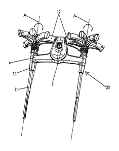
Referring to figures 1 to 3, a garden tool according to
CA 02898940 2015-07-22
WO 2014/114215 - 5 -
PCT/CN2014/070900
a preferred embodiment of the present invention is an
electrical lawn mower, comprising a machine body part 10 for
performing cutting work and an operating control mechanism 20
mounted on the machine body part 10.
The operating control mechanism 20 comprises a control
button 7 and a pair of handles 12 which are arranged on two
sides of the control button 7. The handles 12 of the pair are
each provided with a trigger 6, and the machine can be activated
by pulling a single trigger 6; the pair of handles 12 can also
form a closed area with the machine body, thereby facilitating
the operation. Pull ropes 5 and driving levers 8 are arranged
inside a housing 4 of the operating control mechanism 20, and
when the machine is to be activated, the control button 7 is
pressed down and either of the triggers 6 is closed, so that
the driving levers 8 are pulled by the pull ropes 5, and thus
a switch is triggered.
The operating control mechanism 20 further comprises stop
components 2 and elastic elements 3, which are movable relative
to the handles 12. The stop components 2 are movable downwards
relative to the handles 12, and each is a hollow cylinder and
provided with an operable part 24 on an outer surface thereof.
An inner surface of the stop component 2 is provided with a
first toothed part 22, an outer surface of each of the handles
12 is provided with a second toothed part 14, and the first
toothed part 22 is engagable with the second toothed part 14
so as to limit and secure the stop component 2. The housing
4 is provided with positioning columns 16, and the stop
component 2 is arranged between the positioning column 16 and
the handle 12. Said elastic element 3 is sheathed on the
positioning column 16 and is arranged inside the stop component
2.
CA 02898940 2015-07-22
WO 2014/114215 - 6 -
PCT/CN2014/070900
In this way, when a user needs to rotate a handle 12, he
presses downwards the operable part 22 of the stop component
2, as shown by the arrow F, so that the engagement between the
first toothed part 22 of the stop component 2 and the second
toothed part 14 of the handle 12 is released and thus the handle
12 can rotate around the longitudinal axis A thereof in a range
of 360 degrees, as shown in figure 4.
When the handle 12 is rotated to an appropriate position,
the operable part 24 of the stop component 2 is released, so
that the stop component 2 bounces upwards under a restoring
force of the elastic element 3 to be engaged with the handle
12, thus limiting and securing the handle 12 again, in which
case, the handle 12 can reach a position which is suitable for
operation by the user.
In addition, the operating control mechanism 20 further
comprises two steel tubes 11 which are connected to two sides
of the machine body part 10. Each steel tube 11 is provided
with a rotary mechanism 13 which can rotate around an axis
thereof (not shown in the figures). The steel tube 11 runs
through the positioning column 16 and the stop component 2,
so that the rigidness and strength of the connection
therebetween are enhanced.
Embodiment II
Further referring to figures 5 and 6, in embodiment II,
the operating control mechanism 20' has a structure
substantially similar to that of the operating control
mechanism 20 in embodiment I, and thus identical structures
are denoted with identical reference numbers and are not stated
in detail, only different structures being explained and
illustrated.
A stop component 2' in the present embodiment is provided
CA 02898940 2015-07-22
=
= WO 2014/114215
- 7 - PCT/CN2014/070900
with a first toothed part 22' and an operable part 24' on the
outer surface thereof. An inner surface of each handle 12' is
provided with a second toothed part 14' which is engagable with
the first toothed part 22', and an elastic element 3' is
sheathed on a positioning column 16 and arranged between the
stop component 2 and the handle 12 ' . Pulling the operable part
24 upwards moves the stop component 2' upwards relative to
the handle 12 ' , as shown by the arrow F' , so that the engagement
between the first toothed part 22 and the second toothed part
14' is released and thus the handle 12' can rotate around the
axis A' thereof in a range of 360 degrees.
Embodiment III
Further referring to figures 7 and 8, again in embodiment
III, the operating control mechanism 20" has a structure
substantially similar to those of the operating control
mechanisms 20, 20' in embodiments land II, and thus identical
structures are denoted with identical reference numbers and
are not stated in detail, only different structures being
explained and illustrated.
The operating control mechanism 20" in the present
embodiment comprises handles 12 " , stop components 2 " , casing
tubes 18 which are sheathed on the stop components 2 " , elastic
elements 3" and buttons 19. A lower end part of each of the
stop components 2'' is provided with a first toothed part 22' ' ,
each of the casing tubes 18 is provided with a second toothed
part 14 " , and the first toothed part 22" is engagable with
the second toothed part 14" . Each of the casing tubes 18 is
arranged between the stop component 2" and the handle 12'.
Each of the elastic elements 3" is arranged between the stop
component 2" and the positioning column 16". The buttons 19
are mounted on the handles 12 and are engagable with the stop
CA 02898940 2015-07-22
WO 2014/114215 - 8 -
PCT/CN2014/070900
components 2 " . In this way, when a handle 12'' needs to be
rotated, a button 12" is pressed downwards as shown by the
arrow F'' such that the engagement between the stop component
2" and the casing tube 18 is released and therefore the handle
12'' can rotate around the axis A" thereof in a range of 360
degrees.
Embodiment IV
Further referring to figures 9 to 11, the operating control
mechanism 20" of the present embodiment has a structure
substantially similar to those of the operating control
mechanisms 20, 20 ' , 20'' in embodiments I, II and III, and
thus identical structures are denoted with identical reference
numbers and are not stated in detail, only different structures
being explained and illustrated.
The operating control mechanism 20"' in the present
embodiment comprises handles 12'", stop components 2"', a
pair of elastic elements 3"' and casing tubes 18'. An outer
surface of each of the stop components 2"' is also provided
with an operable part 24" which is used for pulling the stop
component 2"' upwards in the F"' direction, and the stop
component is arranged between a handle 12" ' and a positioning 4
column 16"'. An inner surface of each of the stop components
2"' is provided with a first toothed part 22"', and an outer
surface of the bottom end of each positioning column 16'" is
provided with a second toothed part 14", which is engagable
with the first toothed part 22"'. The casing tubes 18' are
sheathed on the positioning columns 16"' and are arranged
inside the handles 12'". The pair of elastic elements 3'"
is arranged between the stop components 2"' and the handles
12'1'. When a handle 12'" needs to be rotated, pulling the
operable part 24"' upwards moves the stop component 2,"
CA 02898940 2015-07-22
WO 2014/114215 - 9 -
PCT/CN2014/070900
upwards relative to the handle 12"', as shown by the arrow
F"', so that the engagement between the first toothed part
22"' and the second toothed part 14"' is released and thus
the handle 12"' can rotate around the axis A"' thereof in
a range of 360 degrees.
It should be noted that the preferred embodiments are only
provided for illustrating the technical concept and
characteristics of the present invention, for the purpose of
enabling those skilled in the art to understand the content
of the present invention and to implement the present
invention, but not for limiting the scope of protection of the
present invention. Any equivalent variation or modification
of the spirit of the present invention shall be incorporated
in the protective scope of the present invention.