Note : Les descriptions sont présentées dans la langue officielle dans laquelle elles ont été soumises.
CA 02899708 2015-07-29
WO 2014/123423
PCT/N02014/000013
BUTTERFLY VALVE COMPRISING REMOVABLE COUPLING PART
The present invention relates to a butterfly valve for
mounting with couplings or flanges, comprising a valve
housing with a through running boring, in which a rotary
damper, mounted to a spindle, is arranged standing in a
circular-cylindrical valve seat and where the valve seat
is equipped internally with conical contact surfaces for
the damper. Furthermore, the valve housing comprises, on a
first side, a coupling end piece and the valve housing is,
on the opposite side, equipped with several threaded bolt
holes arranged radially around the through running boring.
Today, it is common to use lug type butterfly valves with
threaded bore holes on both sides of the valve. This is a
well tried embodiment which is approved by the
classification societies. However, the fitting is labour
intensive as one must first weld flanges onto the pipe
ends. Thereafter, the valve is centred on the flange and
bolts are tightened. The most common valves are also
vulnerable to poor centring or damages to the flange. If
the fitting procedures are not followed accurately, there
will be a risk for leaks and damages.
In addition, this is a time consuming and thus a costly
procedure. On a modern PSV vessel (platform supply ship),
there are about 250 tonnes of pipe and pipe parts so that
the piping work is one of the most labour intensive and
costly jobs for a such new construction, and particularly
within the ship building industry there is a considerable
saving potential.
Couplings have been on the market for many years, but
have, in the main, been used within fire protection/
CA 02899708 2015-07-29
WO 2014/123423
PCT/N02014/000013
2
sprinklers and plumbing, heating and sanitation. Lately,
there has been only limited industrial application before
now, as Norwegian shipyards have over the last years
started to use couplings to a larger extent. Focus on
savings in time and thereby costs have provided an opening
for this type of equipment. Today, there are two large
suppliers of couplings in the Norwegian market.
As mentioned, there are today a good selection of
equipment and parts for fire protection/sprinklers and
plumbing, heating and sanitation, including valves
suitable for such application areas. However, there are no
valves for this type of coupling that is suitable for use
within ship building and the market is asking for such
valves. The valve according to the invention has a
particular application within the ship building industry,
but can be used in general within any industry and is thus
not limited to the ship building industry.
All the valves one knows for fitting with couplings have
in common that the sealing is in the form of a vulcanised
rubber covering on the damper. The valve housing is
covered with an epoxy compound or similar surface treat-
ment. This makes the valve vulnerable to damages in the
covering both to the housing and the damper. The risk of
corrosion and subsequent leakage is regarded as relatively
large.
Valve types with coupling ends on both sides are not
suited to fitting to the side of a ship. A number of
standard lug valves are used together with flange adapters
for the fitting. This is expensive equipment and not
particularly suited to fitting of standard dampers.
CA 02899708 2015-07-29
WO 2014/123423
PCT/N02014/000013
3
The valve according to the invention is a soft-sealing,
concentric butterfly valve which is leak proof, often with
a two-sided seal. Furthermore, it can have a through
running spindle fastened to the damper via a spline,
square peg or taper pins. Dry spindle, isolated from the
medium.
The components of the soft-sealing butterfly valve
according to the invention are placed in a new housing
with an end piece for fitting to a coupling, such as a
mechanical grooved coupling. It is thus not a quick
coupling, but a fast mechanical connection with bolts that
are tightened to secure the coupling. Examples of pressure
classification can be up to 64 bar for the coupling and 25
bar for the valve.
The valve seat of different materials can be mounted on or
vulcanised on a hard insertion ring or support ring. The
valve seat can have conical contact surfaces for the
damper at the through running of the spindle and also
integrated sealing rings in the opening for the running
through of the spindle. This ensures a leak proof
construction without the use of extra 0-rings.
The valve can have a metal damper in different materials
with a machined sealing surface.
The valve housing according to the invention is preferably
cast in two parts. A main part can have an end pipe piece
for a coupling on the one side and a standard lug
embodiment with threaded bolt holes on the other side. At
the fitting of the lug side against the flange, the valve
will be able to be mounted to the side of the ship, to
flanged pipe parts or components such as filters, pumps,
CA 02899708 2015-07-29
WO 2014/123423
PCT/N02014/000013
4
etc. Mounted on this way the valve can function as a
blinding of a pipe line.
According to the invention a second part in the form of an
end piece, can be in the form of a flanged pipe end piece
where the flange boring is adapted to the boring of the
lug side of the valve. The pipe end is preferably grooved
for mounting with couplings. The valve housing can have an
ISO standardised top flange that makes a direct fitting of
an activator possible. The valve housing has a standard
short neck, but can be supplied with a long neck adapted
to the isolation of pipelines.
A valve according to the invention can have a type of
valve seat that seals against a counter flange without the
use of additional gaskets. The contact edge in the main
part of the valve housing can function as a sealing
surface. When the end piece of the valve housing or a
standard counter flange is mounted on the main part, the
valve seat is compressed between these parts so that a
leak proof connection is created in all joints.
Consequently, it is an object to provide a valve and then
in particular a butterfly valve as described above.
From prior art, reference is made to, among others,
US 6,125,871 A which shows a chemical fluid transfer valve
(for example, for loading/unloading of bulk materials) and
which is formed by a male valve assembly and a female
valve assembly. This relates to a composed sampling valve
with a flushing solution based on loose components and
quick couplings. The butterfly valve is here a standard
wafer valve for insertion between the flanges.
CA 02899708 2015-07-29
WO 2014/123423
PCT/N02014/000013
US 2011163532 Al show a hose coupling for a fire engine
and a method for the use of the system. The hose coupling
is in the form of a quick coupling that makes it possible
to get a quick connection between the fire hose and the
5 fire engine, and even more importantly is that the system
makes it possible to disconnect even faster.
Concerning the above mentioned documents, it shall be
pointed out that in general both solutions relate to quick
couplings. The present invention relates, as mentioned,
not to a quick coupling, which will be clear in the sense
that the valve housing and the coupling part shall be
screwed together, i.e. a solid mechanical connection with
bolts that are tightened to secure the coupling.
Furthermore, the valve according to the invention is a
soft-sealing, concentric butterfly valve which is leak
proof, usually with a two-sided seal.
The above mentioned objects are obtained with a butterfly
valve as given in the independent claim, while alternative
embodiments are given in the respective dependent claims.
According to a first aspect of the invention, a butterfly
valve is provided for mounting with couplings or flanges,
comprising a valve housing with a through running boring,
in which a rotary damper mounted to a spindle is placed
standing in a circular-cylindrical valve seat, and that
the valve seat inside is equipped with conical contact
surfaces for the damper. On a first side, the valve
housing comprises a coupling end piece and the valve
housing is mounted on the opposite side with several
threaded bolt holes arranged radially about the through
running boring. The valve is characterised in that a
removable coupling part comprising a second coupling end
CA 02899708 2015-07-29
WO 2014/123423
PCT/N02014/000013
6
piece is mounted to the other side of the valve housing
and that the coupling part is fastened to the valve
housing with the help of bolts inserted into the threaded
bolt holes, and also that the valve seat is inserted
between the valve housing and the coupling part and
surrounds the damper.
It is preferred that the coupling end piece is cast in one
piece with the valve housing.
The spindle is preferably running through the valve seat
and the valve seat can comprise integrated sealing rings
in the openings for the through running of the spindle.
The removable coupling part preferably comprises a boring
with a similar or identical diameter to the boring in the
valve housing.
Furthermore, the valve housing can be equipped with a neck
encompassing a collar, and an upper part of the spindle
can extend above the collar and make up a rotation pivot.
The valve housing can also comprise, on one or both sides
of the damper, bushes or bearings for the mounting of the
spindle.
The valve housing can also comprise an internal edge,
against which the valve seat lies, where said edge and a
contact surface for a flange connection or the second
coupling part can function as sealing surfaces, as the
valve seat is compressed between these parts to provide a
leak proof connection.
Furthermore the butterfly valve according to the invention
can be surface treated by hot-dip galvanisation.
CA 02899708 2015-07-29
WO 2014/123423 PCT/N02014/000013
7
The invention shall now be described in more detail with
help of the enclosed figures, in which
Figure 1 shows an outline of a butterfly valve
according to the invention.
Figure 2 shows a section of the butterfly valve
according to the invention.
Figure 3 shows a top outline of the butterfly valve
shown in figs 1 and 2.
Figure 4 shows an outline of a removable coupling
part according to the invention.
Figure 5 shows a section of the removable coupling
part according to the invention.
Figure 6 shows an outline of the butterfly valve
according to the invention.
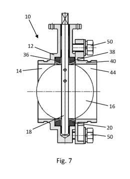
Figure 7 shows a section of the butterfly valve
according to the invention.
Figures 1-3 show a valve housing 12 of a butterfly valve
10 according to the invention. The valve housing 12
comprises in an, in the main, traditional way a spindle 18
that extends vertically through most of the valve housing.
A damper 16 is arranged standing in a through running
boring 14, where the damper is fitted to the spindle 18.
The spindle 18, and thus the damper 16, can be rotated
either manually or automatically with the help of an
activator (not shown). For example, an upper end 32 of the
spindle that extends out of or extends above the valve
housing 12 can function as a rotation pivot and is
activated for rotation of the damper 16 so that flow
through the valve housing is regulated. The valve housing
12 can comprise, on one or both sides of the damper 16,
bushes or bearings 34 for the mounting of the spindle 18.
CA 02899708 2015-07-29
WO 2014/123423 PCT/N02014/000013
8
Furthermore, a valve seat 20 is arranged in the boring 14
and around the damper 16, where the valve seat can be
formed in an, in the main, circular-cylindrical form and
in various materials and which can be cast in a sealing
material and/or which can be fitted on or vulcanised on a
hard insert ring or support ring (for example, as
illustrated in figure 2). The valve seat 20 can have
conical contact surfaces 20a for the damper 16 at the
through running of the spindle and also integrated sealing
rings 26. The valve seat 20 can also be cast, for example,
in one piece of plastic or rubber. Furthermore, the valve
seat 20 lies against an inner edge in the valve housing 12
and a second (not shown) part can provide a corresponding
edge which the valve seat 20 can lie against.
The damper 16 is formed, in principle, in a round shape
with an external diameter that corresponds with the inner
diameter of the valve seat 20, but where the damper at the
through running of the spindle is formed with respective
bevelled and flat top and bottom sections.
The upper part of the valve can comprise, in a known way,
a neck 28 and a top flange 30.
A first side 12a of the valve housing 12 comprises a
coupling end piece 22 for connection and can comprise an
external circular groove 22a for fitting to the coupling.
A second side 12b comprises a coupling surface with
several threaded bolt holes 24 arranged radially about the
boring 14. Thereby, the invention as shown in the figures
1-3, can be connected to a coupling on the one side and to
a standard flange connection (not shown), or the like, to
a pipe on the other side.
CA 02899708 2015-07-29
WO 2014/123423
PCT/N02014/000013
9
The figures 4 and 5 show a second coupling part 40 for use
together with the valve housing 12. The coupling part 40
comprises a pipe piece in the form of a coupling end piece
42 for connecting. In a corresponding way, the coupling
end piece 42 can be fitted with an external circular
groove 42a. The coupling part 42 further comprises a
flange-like connection 48 fitted with several bolt holes
46, where the placing of the bolt holes 46 corresponds to
the bolt holes 24 in the valve housing 12, i.e. with the
same radial centreline.
The figures 6 and 7 show the coupling part 40 fitted to
the valve housing 12. In this preferred embodiment the
butterfly valve according to the invention can be used
between two couplings in a pipe system. As shown in the
figures, the coupling part 40 is securely bolted with the
help of the bolts 50 that run through the bolt holes 24 in
the flange part 48 of the coupling part 40 and which are
screwed into the threaded bolt holes 24 of the valve
housing 12. Thus, this provides a butterfly valve with two
opposite coupling ends. Alternatively, the coupling part
40 can be fastened in other ways or with other means to
the valve housing 12 than those shown in the figures. It
can also be imagined that the coupling part can be cast
integrated with the valve housing in one piece.
The valve seat 20 lies, as shown, against an inner edge 36
in the valve housing 12 and the second coupling part 40
provides a corresponding edge 38 against which the valve
seat 20 lies. Thus, the valve seat 20 is inserted between
the valve housing 12 and the coupling part 40 and
surrounds the damper 16. Thereby, the valve seat 20 seals
without the use of an additional gasket as the edge 36 in
the valve housing 12 and the contact surface 38 of the
CA 02899708 2015-07-29
WO 2014/123423
PCT/N02014/000013
coupling part 40 can function as sealing surfaces so that
the valve seat gets compressed between these two parts and
a watertight connection in all joints is achieved. The
corresponding will be relevant at the use of a standard
5 flange connection instead of the second coupling part, as
described above.
Furthermore, the valve seat will be able to isolate the
valve housing and this is something that can contribute to
10 removing internal wear in the housing.
The butterfly valve can be supplied in a hot-dip
galvanized embodiment. In, for example, a ballast system,
hot-dip galvanisation is a common surface treatment of
components. The valve with the coupling ends is both a
valve and a piece of the pipe system and a corresponding
surface treatment of the valve could therefore be an
important feature. Previously, it has not been common that
valves for use in such pipe systems have been supplied in
hot-dip galvanised embodiments.
It shall also be mentioned that the coupling parts 22,42
can alternatively be connected to the pipes in the pipe
system with the help of a loop coupling, i.e. a loop that
can be tightened with the help of a rotary lifting arm and
is securely locked in a tightened position. The intended
loop coupling is not a real quick coupling, but a coupling
intended for use in installation areas where pipe routes
are often re-laid.