Note : Les descriptions sont présentées dans la langue officielle dans laquelle elles ont été soumises.
FLOOR LEVELING DEVICE
BACKGROUND
100011 The present invention relates to leveling devices, such as devices
for leveling floor
tiles.
[0002] When installing tiles on a floor, it is typically desirable to keep
the tiles flat with
respect to each other. Some prior art devices have been used to facilitate
leveling tiles. One
example of such a device includes a knob that threads onto a shaft positioned
between two tiles.
With this device, however, grout has a tendency to get between the device and
the underside of
the tiles, resulting in improper seating. In addition, as the knob is
tightened, grout may squeeze
out between the tiles and accumulate in the area under the knob without the
user's knowledge.
The grout then needs to be chipped off of the tiles after the knob is removed.
Furthermore, the
knob may not seat properly on top of the tiles if a granular piece of grout
becomes trapped
between the tiles and the knob.
SUMMARY
[0003] In one embodiment, the invention provides a floor leveling device
for leveling tiles.
The floor leveling device includes a base having a plate and a stem. The plate
has a planar upper
surface configured to engage the tiles and an angled lower surface opposite
the planar upper
surface. The stem extends generally perpendicularly from the planar upper
surface. The floor
leveling device also includes a cap coupled to the stem for movement along the
stem.
[0004] In another embodiment, the invention provides a floor leveling
device for leveling
tiles, the floor leveling device comprising:
a base including a plate and a stem extending generally perpendicularly from
the
plate, the stem having a threaded portion, the base having perforations formed
between the
plate and the stem to facilitate separating the stem from the plate; and
a cap threadably coupled to the threaded portion of the stem for movement
along
1
CA 2909720 2018-05-25
the stem, the cap including a threaded bore for receiving the stem and an
aperture spaced apart
from the threaded bore for viewing portions of the tiles beneath the cap;
wherein the cap includes a frustoconically-shaped body; and
wherein the cap also includes a plurality of flanges extending radially
outward from
the frustoconically-shaped body, and wherein the plurality of flanges is
circumferentially spaced
around the frustoconically shaped body.
According to an aspect of the present invention, there is provided a floor
leveling device for
leveling tiles, the floor leveling device comprising:
a base including a plate and a stem extending generally perpendicularly from
the plate,
the stem having a threaded portion, the base having perforations formed
between the plate and
the stem to facilitate separating the stem from the plate; and
a cap threadably coupled to the threaded portion of the stem for movement
along the stem,
the cap including a frustoconically-shaped body having a bottom surface, the
bottom surface
defining a diameter, a threaded bore through the frustoconically-shaped body
and configured to
receive the stem, an aperture through the frustoconically-shaped body spaced
apart from the
threaded bore and configured to allow viewing portions of the tiles beneath
the cap,
a plurality of flanges extending radially outward from the frustoconically-
shaped body,
the plurality of flanges being circumferentially spaced around the
frustoconically shaped body,
and a ridge extending downwardly from the bottom surface and which is
configured to engage
the tiles while reducing friction between the cap and the tiles, the ridge
being a continuous,
annular rib having a diameter that is different than the diameter of the
bottom surface.
[0005] In
yet another embodiment, the invention provides a floor leveling device for
leveling tiles. The floor leveling device includes a base having a plate with
a planar upper surface
configured to engage the tiles, a first angled lower surface opposite the
planar upper surface and
adjacent a first egde of the plate, a second angled lower surface opposite the
planar upper surface
1 a
CA 2909720 2020-03-26
CA 02909720 2015-10-21
and adjacent a second edge of the plate, a first notch formed through the
planar upper surface and
the first angled lower surface at the first edge, and a second notch formed
through the planar
upper surface and the second angled lower surface at the second edge. The base
also has a stem
extending generally perpendicularly from the planar upper surface of the
plate. The stem
includes a threaded portion and a flattened portion positioned between the
plate and the threaded
portion. The floor leveling device also includes a cap threadably coupled to
the threaded portion
of the stem for movement along the stem. The cap includes a plurality of
flanges extending
radially outward from the cap, a plurality of apertures positioned between the
plurality of flanges
for viewing portions of the tiles beneath the cap, and a ridge formed on a
bottom surface of the
cap and configured to engage the tiles.
[0006] Other aspects of the invention will become apparent by consideration
of the detailed
description and accompanying drawings.
BRIEF DESCRIPTION OF THE DRAWINGS
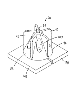
[0007] Fig. 1 is a top perspective view of a floor leveling device
including a base and a cap.
[0008] Fig. 2 is a side view of the floor leveling device.
[0009] Fig. 3 is a top perspective view of the base.
[0010] Fig. 4 is a side view of the base.
[0011] Fig. 5 is a top view of the base.
[0012] Fig. 6 is a top perspective view of the cap.
[0013] Fig. 7 is a bottom perspective view of the cap.
[0014] Fig. 8 is a top perspective view of the floor leveling device in use
with two tiles.
[0015] Fig. 9 is a bottom perspective view of the floor leveling device in
use with two tiles.
[0016] Fig. 10 is a top view of the floor leveling device in use with two
tiles.
2
CA 02909720 2015-10-21
DETAILED DESCRIPTION
[0017] Before any embodiments of the invention are explained in detail, it
is to be
understood that the invention is not limited in its application to the details
of construction and the
arrangement of components set forth in the following description or
illustrated in the following
drawings. The invention is capable of other embodiments and of being practiced
or of being
carried out in various ways.
[0018] Figs. 1-2 illustrate a floor leveling device 20 including a base 24
and a cap 28. The
floor leveling device 20 is usable to help level, for example, tiles on a
floor, wall, or other
surface. In use, a portion of the base 24 is positioned beneath the tiles
(e.g., between the tiles and
the floor), and the cap 28 is moved along another portion of the base 24 to
engage the tiles. The
base 24 and the cap 28 capture portions of the tiles therebetween to help
level and space the tiles
relative to each other. Grout, calk, and/or other bonding or adhesive
materials introduced
underneath and between the tiles to secure the tiles together.
[0019] As shown in Figs. 3-5, the illustrated base 24 includes a plate 32
and a stem 36. The
plate 32 is the portion of the base 24 configured to be positioned beneath the
tiles. The plate 32
includes a planar upper surface 40 that is configured to engage the tiles. The
illustrated upper
surface 40 is planar, or flat, throughout and does not include any bumps or
protrusions extending
upwardly from the surface 40. As shown in Fig. 2, the plate 32 also includes
two angled lower
surfaces 44, 48 and a central planar section 52 that are opposite the planar
upper surface 40. The
angled surfaces 44, 48 extend in opposite directions from the central planar
section 52. The first
angled surface 44 extends from the central planar section 52 to a first edge
56 of the plate 32, and
the second angled surface 48 extends from the central planar section 52 to a
second edge 60 of
the plate 32. The surfaces 44, 48 are angled (i.e., non-parallel) relative to
the planar upper
surface 40 of the plate 32. In the illustrated embodiment, the angled surfaces
44, 48 are oriented
so that the plate 32 decreases in thickness, or tapers, toward the first edge
56 and toward the
second edge 60. This arrangement provides a wedge-shaped profile toward the
first edge 56 and
the second edge 60.
[0020] Referring back to Figs. 3 and 5, the plate 32 also includes two
notches 64, 68. The
first notch 64 is formed through the planar upper surface 40 and the first
angled lower surface 44
3
CA 02909720 2015-10-21
at the first edge 56. The second notch 68 is formed through the planar upper
surface 40 and the
second angled lower surface 48 at the second edge 60. In the illustrated
embodiment, the
notches 64, 68 are generally V-shaped. In other embodiments, the notches 64,
68 may be other
suitable shapes (e.g., U-shaped, rectangular, etc.). In some embodiments, the
plate 32 may
include fewer or more notches at each edge 56, 60. As shown in Fig. 5, sides
72 of the plate 32
are also angled toward the notches 64, 68 so that the overall width of the
plate 32 decreases
toward the first and second edges 56, 60.
[0021] As shown in Figs. 3-4, the stem 36 extends generally perpendicularly
from the planar
upper surface 40 of the plate 32. The illustrated stem 36 includes a threaded
portion 76 and a
flattened portion 80. The threaded portion 76 is formed at a distal or free
end of the stem 36.
The threaded portion 76 includes threads that threadably engage to the cap 28.
The threaded
portion 76 allows the cap 28 to move along the stem 36 toward and away from
the plate 32. In
some embodiments, the threaded portion 76 may be replaced with a toothed
portion that engages
the cap 28 via a ratchet-type mechanism. In the illustrated embodiment, the
threaded portion 76
accounts for a majority (i.e., over 50 percent) of the overall length of the
stem 36. In some
embodiments, the threaded portion 76 may extend the entire length of the stem
36, and the
flattened portion 80 may be omitted.
[0022] The flattened portion 80 is positioned between the plate 32 and the
threaded portion
76. The flattened portion 80 is shaped and sized to create and maintain a
desired spacing
between adjacent tiles. The illustrated flattened portion 80 includes two
vertically-extending,
planar surfaces 84 that are configured to engage and space apart edges of two
tiles. The planar
surfaces 84 provide the flattened portion 80 with a generally rectangular
cross-section to fit
between the tiles. In other embodiments, the flattened portion 80 may have an
X- or cross-
shaped cross-section to fit between and space apart four tiles at their
corners.
[0023] As shown in Fig. 4, the illustrated base 24 also includes
perforations 88 founed
between the plate 32 and the stem 36. In particular, the perforations 88 are
formed between the
upper surface 40 of the plate 32 and the flattened portion 80 of the stem 36.
The perforations 88
may be, for example, notches or score lines to remove material between the
plate 32 and the stem
36. The perforations 88 facilitate separating (e.g., snapping apart) the stem
36 from the plate 32.
4
CA 02909720 2015-10-21
[0024] Figs. 6 and 7 illustrate the cap 28 of the floor leveling device 20.
The cap 28 couples
to the stem 36 to capture portions of tiles between the cap 28 and the plate
32. In the illustrated
embodiment, the cap 28 is threadably coupled to the threaded portion 76 of the
stem 36. This
threaded connection allows the cap 28 to move along the stem 36 toward and
away from the
plate 32.
[0025] The illustrated cap 28 includes a body 92, a plurality of flanges
96, and a plurality of
apertures 100. In the illustrated embodiment, the body 92 is a frustoconically-
shaped body
having a larger diameter end 104 near the plate 32 of the base 24, and a
smaller diameter end 108
opposite from the plate 32 of the base 24. The body 92 includes a threaded
bore 112 (Fig. 6) at
the smaller diameter end 108. The threaded bore 112 receives and engages the
threaded portion
76 of the stem 36. The body 92 also includes an inner bore 116 (Fig. 7)
extending from the
larger diameter end 104 to the threaded bore 112. The inner bore 116 is sized
to at least partially
receive the flattened portion 80 of the stem 36 when the cap 28 is threaded
onto the stem 36.
The inner bore 116 thereby provides clearance in the cap 28 for the cap 28 to
fit over the
flattened portion 80 and move closer to the plate 32.
[0026] The flanges 96 extend radially outward from the body 92. In the
illustrated
embodiment, the cap 28 includes five flanges 96 that are circumferentially
spaced around the
body 92. Each flange 96 provides a handle or grip to facilitate turning the
cap 28 on the stem 36
of the base 24. In other embodiments, the cap 28 may include fewer or more
flanges.
Additionally or alternatively, the flanges 96 may be spaced in different
arrangements around the
cap 28. In some embodiments, the flanges 96 may be omitted so that a user
directly grasps the
body 92 of the cap 28 to turn the cap 28.
[0027] The apertures 100 are formed through the body 92. In the illustrated
embodiment, the
cap 28 includes five apertures 100 that are circumferentially spaced around
the body 92 of the
cap 28. The illustrated apertures 100 are equally spaced apart such that each
aperture 100 is
positioned between two adjacent flanges 96. In other embodiments, the cap 100
may include
fewer or more apertures. Additionally or alternatively, the apertures 100 may
be spaced in
different arrangements around the cap 28. The illustrated apertures 100 extend
in a direction
generally parallel to an axis of rotation of the cap 28 (and, thereby, a
longitudinal axis of the
CA 02909720 2015-10-21
stem 36). Orienting the apertures 100 in this manner provides a view through
the cap 28 so that
a user can see areas beneath the cap. More specifically, the apertures 100
allow a user to view
portions of the tiles beneath the cap 28 to see, for example, if grout is
squeezing out between the
tiles underneath the cap 28.
[00281 As shown in Figs. 2 and 7, the cap 28 also includes a ridge 120
formed on a bottom
surface 124 of the body 92 (i.e., the surface of the body 92 at the larger
diameter end 104 and
facing the plate 32). The ridge 120 extends downwardly from the body 92 toward
the plate 32 of
the base 24. In the illustrated embodiment, the ridge 120 is a continuous,
annular rib formed on
the bottom surface 124 of the cap 28. In other embodiments, the ridge 120 may
include a series
of discrete bumps or ribs formed on the bottom surface 124 of the cap 28. The
ridge 120 is
configured to engage upper surfaces of the tiles when the cap 28 is threaded
onto the stem 36 of
the base 24 to reduce the chance of grout getting caught between the cap 28
and the tiles. The
ridge 120 also reduces friction between the cap 28 and the tiles when spinning
the cap 28 onto
the base 24. Furthermore, the ridge 120 reduces the possibility of marring the
tiles as the cap 28
is spun onto the base 24.
[0029] In the illustrated embodiment, the base 24 and the cap 28 are
composed of plastic
(e.g., polyethylene, polyvinyl chloride, nylon, etc.). More particularly, the
base 24 and the cap
28 are made of molded or injection molded plastic. In other embodiments, the
base 24 and the
cap 28 may be made of other or differing materials. For example, the base 24
may be made of
plastic, and the cap 28 may be made of metal or wood. Alternatively, the base
24 and the cap 28
may be made of different types of plastics.
100301 Figs. 8-10 illustrate the floor leveling device 20 in use. During
use, the plate 32 of
the base 24 is positioned between two adjacent tiles 128. This may occur by,
for example,
positioning one tile 128 on a floor (which is coated with grout), sliding
approximately half of the
plate 32 under the tile 128 so that the flattened portion 80 of the stem 36
abuts the edge of the tile
128, and positioning the other tile 128 on top of the other half of plate 32
so that the flattened
portion 80 of stem 36 abuts the edge of the other tile 128. As the plate 32 is
slid under the tile
128 (and the other tile 128 is slid onto the plate 32), the planar upper
surface 40 of the plate 32
scrapes grout off of the underside of the tile 128, creating a relatively
clean interface between the
6
CA 02909720 2015-10-21
plate 32 and the tile 128. The notches 64, 68 and the angled lower surfaces
44, 48 of the plate 32
also reduce the amount of space taken up by the plate 32 so that excess grout
may accumulate
within the notches 64, 68 or under the angled lower surfaces 44, 48 without
being displaced
unfavorably elsewhere.
[0031] After the plate 32 is installed under the tiles 128, the cap 28 is
coupled to the stem 36.
In the illustrated embodiment, the cap 28 is threaded (e.g., spun or rotated)
onto the threaded
portion 76 of the stem 36. As the cap 28 is threaded onto the stem 36, a user
can see if any grout
is squeezed out from between the tiles 120 using the apertures 100 (as viewed
in Fig. 10). The
user can then clean/remove the grout before the grout hardens on the upper
surfaces of the tiles
128. The cap 28 is threaded onto the stem 36 until the ridge 120 on the bottom
surface 124
engages the tiles 128. Once the ridge 120 engages the tiles 128, further
tightening of the cap 28
can shift the tiles 128 vertically to help level the tiles 128 relative to
each other. This process can
be performed on all of the tiles 128 on a floor or other surface.
[0032] Once the tiles 128 are leveled and set (e.g., once the grout
hardens), the cap 28 is
removed (e.g., unthreaded) from the stem 36 of the base 24. Then, the stem 36
is separated from
the plate 32 by, for example, snapping the stem 36 apart from the plate 32
along the perforations
88 (Fig. 4). Once the cap 28 and the stem 36 are removed, gaps between the
tiles 128 can be
filled with grout. The plates 32 are left beneath the tiles 128 and covered by
the grout.
[0033] Various features and advantages of the invention are set forth in
the following claims.
7