Sélection de la langue

Search

Sommaire du brevet 2915301 

Énoncé de désistement de responsabilité concernant l'information provenant de tiers

Une partie des informations de ce site Web a été fournie par des sources externes. Le gouvernement du Canada n'assume aucune responsabilité concernant la précision, l'actualité ou la fiabilité des informations fournies par les sources externes. Les utilisateurs qui désirent employer cette information devraient consulter directement la source des informations. Le contenu fourni par les sources externes n'est pas assujetti aux exigences sur les langues officielles, la protection des renseignements personnels et l'accessibilité.

Disponibilité de l'Abrégé et des Revendications

L'apparition de différences dans le texte et l'image des Revendications et de l'Abrégé dépend du moment auquel le document est publié. Les textes des Revendications et de l'Abrégé sont affichés :

  • lorsque la demande peut être examinée par le public;
  • lorsque le brevet est émis (délivrance).
(12) Brevet: (11) CA 2915301
(54) Titre français: MECANISME DE PRODUCTION DE RAYONNEMENT ELECTROMAGNETIQUE
(54) Titre anglais: SYSTEM FOR PRODUCING ELECTROMAGNETIC RADIATION
Statut: Octroyé
Données bibliographiques
(51) Classification internationale des brevets (CIB):
  • H01J 23/06 (2006.01)
  • H01J 25/00 (2006.01)
  • H05H 9/02 (2006.01)
(72) Inventeurs :
  • BIRNBACH, CURTIS A. (Etats-Unis d'Amérique)
(73) Titulaires :
  • ADVANCED FUSION SYSTEMS LLC (Etats-Unis d'Amérique)
(71) Demandeurs :
  • ADVANCED FUSION SYSTEMS LLC (Etats-Unis d'Amérique)
(74) Agent: MOFFAT & CO.
(74) Co-agent:
(45) Délivré: 2016-09-13
(22) Date de dépôt: 2007-05-30
(41) Mise à la disponibilité du public: 2008-03-20
Requête d'examen: 2015-12-14
Licence disponible: S.O.
(25) Langue des documents déposés: Anglais

Traité de coopération en matière de brevets (PCT): Non

(30) Données de priorité de la demande:
Numéro de la demande Pays / territoire Date
60/809,453 Etats-Unis d'Amérique 2006-05-30
11/754,928 Etats-Unis d'Amérique 2007-05-29

Abrégés

Abrégé français

L'invention concerne un système pour produire un rayonnement électromagnétique avec amélioration à partir d'un tube de dérivation contenant une structure Smith-Purcell cylindrique. Le système comprend un oscillateur linéaire magnétiquement isolé. L'oscillateur comprend une cavité résonante cylindrique ayant un canon à électrons à ondes progressives et une anode connexe. Le tube de glissement est formé d'un élément conducteur cylindrique creux qui est positionné à l'intérieur d'une cavité résonante de l'oscillateur. Le tube de dérivation comprend une surface interne et une paire d'extrémités. Le tube de dérivation peut être adapté de telle sorte que l'interaction entre un faisceau d'électrons, à partir du canon à électrons, passe à travers l'espace intérieur du tube de dérivation, et la grille interne, de manière à produire un rayonnement RF par l'effet de Smith-Purcell. L'espacement, l'angle de face et la forme de la grille et l'énergie du faisceau d'électrons sont des déterminants de la fréquence du rayonnement RF.


Abrégé anglais

Disclosed is a system for producing electromagnetic radiation with enhancement from a drift tube containing a cylindrical Smith-Purcell structure. The system includes a magnetically insulated linear oscillator. The oscillator includes a cylindrical resonant cavity having a traveling wave electron gun and a cooperating anode. The drift tube is formed of a hollow cylindrical conductive element that is positioned within a resonant cavity of the oscillator. The drift tube includes an inner surface and a pair of ends. The drift tube may be adapted such that the interaction between an electron beam, from the electron gun, passes through the inner space of the drift tube, and the internal grating, so as to produce RF radiation by the Smith-Purcell Effect. Spacing, face angle and shape of the grating, and the energy of the electron beam are determinants of the frequency of the RF radiation.

Revendications

Note : Les revendications sont présentées dans la langue officielle dans laquelle elles ont été soumises.


WHAT IS CLAIMED IS:
1. System for producing electromagnetic radiation with enhancement from a
drift tube
containing a cylindrical Smith-Purcell structure, comprising:
a) a magnetically insulated linear oscillator having a cylindrical resonant
cavity
containing a traveling wave electron gun and cooperating anode, and further
containing a drift tube positioned between the traveling wave electron gun and

the cooperating anode;
b) the drift tube being formed of a hollow cylindrical conductive element that
is
positioned within said resonant cavity and that is electrically isolated from
the
traveling wave electron gun, wherein a cylindrical axis of the drift tube is
coaxial
with a main axis of the resonant cylindrical cavity in a region between said
electron gun and said anode;
c) the drift tube having an inner surface and a pair of ends; the hollow
cylindrical
conductive element being enhanced by containing a cylindrical Smith-Purcell
grating surface formed on the inner surface of the drift tube; said grating
surface
comprising a reflection grating surface having a series of ridges spaced apart
by
respective grooves; said reflection grating surface extending for at least a
majority
of the length of the drift tube;
d) the drift tube being adapted so that an electron beam, from the electron
gun,
passes through the inner space of the drift tube and interacts with the Smith-
Purcell grating surface, so as to produce RF radiation by Smith-Purcell
Effect; and
e) the drift tube being further adapted so that spacing, face angle and shape
of
Smith-Purcell grating surface, and an energy of the electron beam are
determinants of the frequency of the RF radiation.
2. The system of Claim 1, wherein the Smith-Purcell grating surface comprises
an internal
thread extending for at least a majority of length of the drift tube.
6

3. The system of Claim 1 or 2, wherein each ridge of the reflection grating
surface has a
cross-section, taken along a plane passing through said cylindrical axis of
the drift tube,
comprising a triangle having one side parallel to said cylindrical axis.
7

Description

Note : Les descriptions sont présentées dans la langue officielle dans laquelle elles ont été soumises.

CA 02915301 2015-12-14
SYSTEM FOR PRODUCING ELECTROMAGNETIC RADIATION
RELATED APPLICATIONS
[0001] This application is a divisional application of Canadian Patent
Application No. 2653707,
filed May 30, 2007, for Method and System for Internal Confinement Fusion
Reactions.
FIELD OF THE INVENTION
[0002] The present invention relates to a system for producing
electromagnetic radiation
incorporating a drift tube modified to enable output of higher frequencies
from a high power RF
source incorporating the drift tube.
BACKGROUND OF THE INVENTION
[0003] Prior art Magnetically Insulated Linear Oscillators (MIL05) are
high power RF sources,
which have typical outputs between 300 MHz and 3.5 GHz. For various
applications, it would be
desirable to provide a high power RF source that can achieve even higher
frequencies.
SUMMARY OF THE INVENTION
[0004] The present invention relates to a system for producing
electromagnetic radiation
incorporating a drift tube which includes a hollow cylindrical conductive
element having a grating
surface formed on its inner surface, with the ends of the cylindrical
conductive element being
radiused to minimize electrical stress buildup.
[0005] The interaction between a relativistic electron beam from an
electron source passing
through the inner space of the hollow element and the internal grating
produces RF radiation by
the Smith-Purcell Effect. The spacing, face angle and shape of the grating,
and the energy of the
electron beam, are determinants of the frequency of the RF radiation.
1

CA 02915301 2016-04-04
[0006] Accordingly then, in one aspect, there is provided a system for
producing
electromagnetic radiation with enhancement from a drift tube containing a
cylindrical Smith-
Purcell structure, comprising: a magnetically insulated linear oscillator
having a cylindrical
resonant cavity containing a traveling wave electron gun and cooperating
anode, and further
containing a drift tube positioned between the traveling wave electron gun and
the cooperating
anode; the drift tube being formed of a hollow cylindrical conductive element
that is positioned
within said resonant cavity and that is electrically isolated from the
traveling wave electron gun,
wherein a cylindrical axis of the drift tube is coaxial with a main axis of
the resonant cylindrical
cavity in a region between said electron gun and said anode; the drift tube
having an inner surface
and a pair of ends; the hollow cylindrical conductive element being enhanced
by containing a
cylindrical Smith-Purcell grating surface formed on the inner surface of the
drift tube; said grating
surface comprising a reflection grating surface having a series of ridges
spaced apart by respective
grooves; said reflection grating surface extending for at least a majority of
the length of the drift
tube; the drift tube being adapted so that an electron beam, from the electron
gun, passes
through the inner space of the drift tube and interacts with the Smith-Purcell
grating surface, so as
to produce RF radiation by Smith-Purcell Effect; and the drift tube being
further adapted so that
spacing, face angle and shape of Smith-Purcell grating surface, and an energy
of the electron beam
are determinants of the frequency of the RF radiation.
[0007] The foregoing drift tube, having a grating on the inner surface
of a cylindrical drift tube,
can be used advantageously to increase the frequency output of such devices as
a Magnetically
Insulated Linear Oscillator (MILO) beyond the aforementioned range of 300 MHz
to 3.5 GHz
mentioned for a MILO.
DESCRIPTION OF THE DRAWINGS
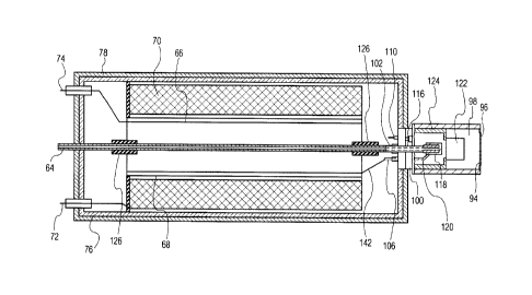
[0008] FIG. 1 is a sectional view along the length of a combined SXE-MILO
driver.
[0009] FIG. 2 is a partly sectional view along the length of the MILO RF
head of FIG 1.
2

CA 02915301 2015-12-14
[00010] FIG. 3A is a sectional view along the length of a Drift Tube used
in the MILO RE head of
FIG. 1, and FIG. 3B is an enlarged view of the circled region in FIG. 3A
entitled "FIG. 3B".
DETAILED DESCRIPTION OF THE INVENTION
[00011] A list of drawing reference numbers, their associated parts and
preferred materials for
the parts can be found near the end of this description of the preferred
embodiments.
RF Energy Drivers
[00012] FIG. 1 shows a cross-section of a Stimulated X-ray Emitter (SXE)
combined with a
Magnetically Insulated Linear Oscillator (MILO) at the output (right-shown)
end of the SXE. The
Stimulated X-ray Emitters were first described by the inventor of this current
invention in U.S.
Patent No. 4,723,263. The MILO is another well known, high power RE source,
similar to the
Vircator. The significant difference is that it can produce much higher
frequencies than the
Vircator. Structurally, the major difference is the incorporation of a drift
tube 122 of FIG. 3A and
use of a Traveling Wave Electron Gun (TWEG) instead of the planar cathode 90
and grid 92 of the
Vircator. There is a resonant cavity 98 and its dimensions in conjunction with
the dimensions of
the drift tube 122 (FIG. 3A) determine the output range. Conventional MILO
devices have outputs
between 300 MHz and 3.5 GHz. The inventor of the present invention has
experimentally verified
that by placing a grating surface on the inner face of the drift tube 122
(FIG. 3A), as shown in FIG.
3B, it is possible to generate RE at much higher frequencies than those
available from a smooth
bore drift tube 122. The source of this RE is due to the Smith-Purcell effect
which describes the
interaction of a relativistic electron beam with a grating surface 123.
Outputs in the THz range are
possible. The grating surface can be formed by many methods. The spacing, face
angle and
grating geometry all are determinants in the frequency achieved (FIG. 3B). It
has been determined
that the preferred embodiment of the drift tube grating is an internal thread
as shown in FIGS. 3A
and 3B. By altering the thread parameters, the output frequency is changed.
The ends of the Drift
3

CA 02915301 2015-12-14
Tube 125 are radiused to minimize formation of undesirable electric field
perturbations inside the
Resonant Cavity 98.
[00013] The balance of the SXE¨MILO driver is the same as the SXE-
Vircator. In fact, the RF
heads¨Vircator and MILO¨can be interchanged. As in the case of the SXE-
Vircator, the TWEG of
the MILO has a hollow center through which the x-rays pass. The electron
output from the TWEG
is compressed by the drift tube 122 and oscillates in the resonant cavity 98.
Drawing Reference Numbers
[00014] The following list of drawing reference numbers has three
columns. The first column
includes drawing reference numbers; the second column specifies the parts
associated with the
reference numbers; and the third column mentions a preferred material (if
applicable) for the
parts.
REFERENCE NUMBER LIST PREFERRED MATERIAL
64 Anode Refractory Metal; Hi-Z
66 Grid Refractory Metal
68 Cathode Graphite (Preferred Embodiment)
70 Coaxial Capacitor Dielectric/Metal Layers
72 Cathode Feedthrough Ceramic & Metal
74 Grid Feedthrough Ceramic & Metal
78 Radiation Shield Lead
94 Anode Mesh Refractory Metal
96 Output Window RF Transparent Low-Z Ceramic
98 Resonant Circular Cavity Stainless Steel or Copper
100 Mounting Flange Stainless Steel
4

CA 02915301 2015-12-14
102 Cathode Feedthrough Ceramic & Metal
106 Grid Feedthrough Ceramic & Metal
110 Getter Pump n/a
112 Getter Pump Feedthrough Ceramic & Metal
114 MILO Cathode Graphite
116 MILO Cathode Support Refractory Metal
118 MILO Grid Refractory Metal
120 MILO Grid support Refractory Metal
122 Drift Tube Refractory Metal
123 Grating Surface Refractory Metal
124 Drift Tube Support Ceramic
125 Radiused end of Drift Tube Refractory Material
126 Internal Anode Insulator Ceramic
142 Grid Output Terminal Refractory Metal
[00015] The foregoing describes a drift tube where the inclusion of a
grating surface on the
inner surface of the tube generates higher frequencies of RF radiation.
[00016] While the invention has been described with respect to specific
embodiments by way
of illustration, many modifications and changes will occur to those skilled in
the art. It is, therefore,
to be understood that the appended claims are intended to cover all such
modifications and
changes as fall within the true scope of the invention.
5

Dessin représentatif
Une figure unique qui représente un dessin illustrant l'invention.
États administratifs

Pour une meilleure compréhension de l'état de la demande ou brevet qui figure sur cette page, la rubrique Mise en garde , et les descriptions de Brevet , États administratifs , Taxes périodiques et Historique des paiements devraient être consultées.

États administratifs

Titre Date
Date de délivrance prévu 2016-09-13
(22) Dépôt 2007-05-30
(41) Mise à la disponibilité du public 2008-03-20
Requête d'examen 2015-12-14
(45) Délivré 2016-09-13

Historique d'abandonnement

Il n'y a pas d'historique d'abandonnement

Taxes périodiques

Dernier paiement au montant de 253,00 $ a été reçu le 2024-05-22


 Montants des taxes pour le maintien en état à venir

Description Date Montant
Prochain paiement si taxe générale 2025-05-30 624,00 $
Prochain paiement si taxe applicable aux petites entités 2025-05-30 253,00 $

Avis : Si le paiement en totalité n'a pas été reçu au plus tard à la date indiquée, une taxe supplémentaire peut être imposée, soit une des taxes suivantes :

  • taxe de rétablissement ;
  • taxe pour paiement en souffrance ; ou
  • taxe additionnelle pour le renversement d'une péremption réputée.

Les taxes sur les brevets sont ajustées au 1er janvier de chaque année. Les montants ci-dessus sont les montants actuels s'ils sont reçus au plus tard le 31 décembre de l'année en cours.
Veuillez vous référer à la page web des taxes sur les brevets de l'OPIC pour voir tous les montants actuels des taxes.

Historique des paiements

Type de taxes Anniversaire Échéance Montant payé Date payée
Requête d'examen 400,00 $ 2015-12-14
Enregistrement de documents 100,00 $ 2015-12-14
Le dépôt d'une demande de brevet 200,00 $ 2015-12-14
Taxe de maintien en état - Demande - nouvelle loi 2 2009-06-01 50,00 $ 2015-12-14
Taxe de maintien en état - Demande - nouvelle loi 3 2010-05-31 50,00 $ 2015-12-14
Taxe de maintien en état - Demande - nouvelle loi 4 2011-05-30 50,00 $ 2015-12-14
Taxe de maintien en état - Demande - nouvelle loi 5 2012-05-30 100,00 $ 2015-12-14
Taxe de maintien en état - Demande - nouvelle loi 6 2013-05-30 100,00 $ 2015-12-14
Taxe de maintien en état - Demande - nouvelle loi 7 2014-05-30 100,00 $ 2015-12-14
Taxe de maintien en état - Demande - nouvelle loi 8 2015-06-01 100,00 $ 2015-12-14
Taxe de maintien en état - Demande - nouvelle loi 9 2016-05-30 100,00 $ 2016-04-27
Expiré 2019 - Modifications après acceptation 400,00 $ 2016-06-28
Taxe finale 150,00 $ 2016-07-18
Taxe de maintien en état - brevet - nouvelle loi 10 2017-05-30 125,00 $ 2017-05-24
Taxe de maintien en état - brevet - nouvelle loi 11 2018-05-30 125,00 $ 2018-05-18
Taxe de maintien en état - brevet - nouvelle loi 12 2019-05-30 125,00 $ 2019-05-20
Taxe de maintien en état - brevet - nouvelle loi 13 2020-06-01 125,00 $ 2020-05-19
Taxe de maintien en état - brevet - nouvelle loi 14 2021-05-31 125,00 $ 2021-05-17
Taxe de maintien en état - brevet - nouvelle loi 15 2022-05-30 229,04 $ 2022-05-16
Taxe de maintien en état - brevet - nouvelle loi 16 2023-05-30 236,83 $ 2023-05-22
Taxe de maintien en état - brevet - nouvelle loi 17 2024-05-30 253,00 $ 2024-05-22
Titulaires au dossier

Les titulaires actuels et antérieures au dossier sont affichés en ordre alphabétique.

Titulaires actuels au dossier
ADVANCED FUSION SYSTEMS LLC
Titulaires antérieures au dossier
S.O.
Les propriétaires antérieurs qui ne figurent pas dans la liste des « Propriétaires au dossier » apparaîtront dans d'autres documents au dossier.
Documents

Pour visionner les fichiers sélectionnés, entrer le code reCAPTCHA :


Pour visualiser une image, cliquer sur un lien dans la colonne description du document. Pour télécharger l'image (les images), cliquer l'une ou plusieurs cases à cocher dans la première colonne et ensuite cliquer sur le bouton "Télécharger sélection en format PDF (archive Zip)" ou le bouton "Télécharger sélection (en un fichier PDF fusionné)".

Liste des documents de brevet publiés et non publiés sur la BDBC .

Si vous avez des difficultés à accéder au contenu, veuillez communiquer avec le Centre de services à la clientèle au 1-866-997-1936, ou envoyer un courriel au Centre de service à la clientèle de l'OPIC.


Description du
Document 
Date
(yyyy-mm-dd) 
Nombre de pages   Taille de l'image (Ko) 
Abrégé 2015-12-14 1 18
Description 2015-12-14 5 155
Revendications 2015-12-14 1 39
Dessins 2015-12-14 3 113
Dessins représentatifs 2015-12-23 1 29
Page couverture 2016-01-26 1 65
Description 2016-04-04 5 156
Revendications 2016-04-04 1 40
Revendications 2016-06-28 2 41
Page couverture 2016-08-16 1 66
Correspondance 2016-07-18 1 48
Correspondance 2016-06-22 1 35
Nouvelle demande 2015-12-14 16 564
Complémentaire - Certificat de dépôt 2015-12-23 1 146
Poursuite-Amendment 2015-12-14 65 2 570
Demande d'examen 2016-02-05 4 234
Modification 2016-04-04 5 186
Paiement de taxe périodique 2016-04-27 1 56
Modification après acceptation 2016-06-13 4 93
Modification après acceptation 2016-06-28 4 123
Correspondance 2016-07-11 1 23