Note : Les descriptions sont présentées dans la langue officielle dans laquelle elles ont été soumises.
CA 02921919 2016-02-25
Intelligent Hydraulic Robotic Arm (IHRA) for Pipe Racking on Drilling Rigs
DETAILED DESCRIPTION
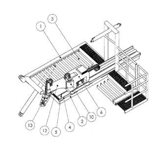
Intelligent Hydraulic Robotic Arm (IHRA) for Pipe Racking is mounted on the
diving board (2) of the
racking board (1), either on the top (FIG 1 and FIG 3) or bellow the diving
board (FIG 2). It transfers
pipe (drill pipe, drill collar) or stands of pipes on the drilling rig from
well centre, or from other
position defined by top drive tilting links and elevator, to locations between
racking board fingers
(3) as needed, and vice versa.
Track assembly (4) with pin rack (5) is mounted on or bellow the diving board
(2). Intelligent
Hydraulic Robotic Arm (IHRA) Carriage (6) runs on track assembly using pin
gear and pin racks. Pin
Gear is driven by hydraulic motor coupled with planetary gearbox drive (8)
with encoder which
provides exact position of the carriage to computer (9) (FIG 4). SCARA Robot
First Arm (12) is
mounted on the carriage. It comprises Helical Hydraulic Rotary Actuator (10)
coupled with encoder
(11), second Helical Hydraulic Rotary Actuator (14) coupled with encoder (15).
SCARA second arm
(13) with jaw (16) is mounted on second Helical Hydraulic Rotary Actuator (FIG
4).
Jaw (16) embedded in second arm (13) has a body (17), two jaw arms (18) that
moves outward'and
inward to adjust to pipe size (FIG 5 and FIG 6), two jaw fingers (19) that
rotates from horizontal to
vertical position and vice versa to engage and disengage the pipe (FIG 5 and
FIG 6). Movement of
jaw arms is provided by hydraulic cylinder and jaw fingers rotation is
provided by pair of Helical
Hydraulic Rotary Actuators (20). Sensors (21) provide signals to computer (9)
to track exact pipe
position before engagement. Sensors (22) embedded in body (17) and jaw arms
(18) confirm jaw
engagement and disengagement to and from pipe.
Pipe handler is operated from the console in driller cabin by computer
controlled one touch trip in,
or trip out cycle with sequential activation, and manual over raid with joy
stick and CTV
supervision.
1
CA 02921919 2016-02-25
Intelligent Hydraulic Robotic Arm (IHRA) for Pipe Racking on Drilling Rigs
ABSTRACT:
Method and system for transferring pipe (drill pipe, drill collar) or stands
of pipes on the drilling rig
from well centre, or from other position defined by top drive tilting links
and elevator, to locations
between racking board fingers as needed, and vice versa, using Intelligent
Hydraulic Robotic Arm
(IHRA).
BACKAROUND OF THE INVENTION
Field of invention is handling pipes and pipe stands on the drilling rig for
oil and gas.
In the oil and gas industry, when a drilling rig drills oil and gas wells,
pipes (drill pipes, drill collars)
are repeatedly inserted and removed from the well. When removed from the well,
pipe stands are
stacked, vertically, on the rig floor and horizontally restrained in the
Racking Board located on the
drilling rig mast (derrick), 50 or 80 feet above the rig floor. To manipulate
pipe stands human
(derrick-man) is required on the racking board. Within the drilling rig crew,
the derrick man has
one of the most dangerous and demanding position.
The existing solutions to replace derrick man, currently in place on the
drilling rigs are based on
electric, hydraulic and mechanical equipment remotely controlled or controlled
by PLC. These
rarely fulfill expectations regarding reliability, motion dynamic and safety
and must be combined
with manual operations.
A wide variety of racking systems, apparatus, and methods for drilling rigs
are known, and many of
them shown in US Patents: 4013178, 4042123, 4044895, 4128135, 4269554,
4274778,
4345864,4462733, 4647100, 4715761, 4725179, 4738321, 4744710, 4765401,
4862973, 5451129,
5465799, 5711382, 5988299, 6003400, 6779614, 6821071, 6976540, 6997265,
7083007, 7140453,
7178612, 7249639, 7293607, 7510028,
SUMMARY OF INVENTION
An aspect of invention provides system for transferring pipe (drill pipe,
drill collar) or stands of
pipes on the drilling rig from well centre, or from other position defined by
top drive tilting links
and elevator, to locations between racking board fingers as needed, and vice
versa, thus providing
1
CA 02921919 2016-02-25
efficient tripping operations without the need for a man on the racking board,
and ads to safety
and efficiency of the drilling operations.
Intelligent Hydraulic Robotic Arm (IHRA) for Pipe Racking utilizes combination
of cartezian robot
concept and SCARA (selective-compliance-articulated robot arms) robot to
achieve compact and
light, but still robust design. Intelligent Hydraulic Robotic Arm (IHRA)
consists from: a track
assembly mounted on or bellow diving board of the racking board, a carriage
driven with hydraulic
motor, coupled with planetary gearbox, moving alongside the track assembly, a
carriage mounted
SCARA first arm driven by Helical Rotary Actuator, SCARA second arm driven by
second Helical
Rotary Actuator, jaw, embedded in SCARA second arm, hydraulically actuated to
grab the pipe,
and a computer system with software and hardware for control and close loop
servo system.
System provides computer controlled one touch trip in, or trip out cycle with
sequential activation,
and manual over raid with joy stick and CTV supervision.
DRAWING DESCRIPTION
FIG 1 is isometric view of Intelligent Hydraulic Robotic Arm (IHRA) for Pipe
Racking mounted
above diving board of the drilling rig racking board.
FIG 2 is isometric view of Intelligent Hydraulic Robotic Arm (IHRA) for Pipe
Racking mounted
bellow diving board of the drilling rig racking board.
FIG 3 is top view of Intelligent Hydraulic Robotic Arm (IHRA) for Pipe Racking
mounted above
diving board of the drilling rig racking board.
FIG 4 is detail view of Intelligent Hydraulic Robotic Arm (IHRA) for Pipe
Racking
FIG 5 is detail view of jaw assembly embedded in second SCARA arm ( jaw arms
closed, jaw finger
in horizontal position).
FIG 6 is detail view of jaw assembly embedded in second SCARA arm (jaw arms
open, jaw finger in
vertical position).
DETAILED DESCRIPTION
Intelligent Hydraulic Robotic Arm (IHRA) for Pipe Racking is mounted on the
diving board (2) of the
racking board (1), either on the top (FIG 1 and FIG 3) or bellow the diving
board (FIG 2). It transfers
pipe (drill pipe, drill collar) or stands of pipes on the drilling rig from
well centre, or from other
position defined by top drive tilting links and elevator, to locations between
racking board fingers
(3) as needed, and vice versa.
2
CA 02921919 2016-02-25
Track assembly (4) with pin rack (5) is mounted on or bellow the diving board
(2). Intelligent
Hydraulic Robotic Arm (IHRA) Carriage (6) runs on track assembly using pin
gear and pin racks. Pin
Gear is driven by hydraulic motor coupled with planetary gearbox drive (8)
with encoder which
provides exact position of the carriage to computer (9) (FIG 4). SCARA Robot
First Arm (12) is
mounted on the carriage. It comprises Helical Hydraulic Rotary Actuator (10)
coupled with encoder
(11), second Helical Hydraulic Rotary Actuator (14) coupled with encoder (15).
SCARA second arm
(13) with jaw (16) is mounted on second Helical Hydraulic Rotary Actuator (FIG
4).
Jaw (16) embedded in second arm (13) has a body (17), two jaw arms (18) that
moves outward and
inward to adjust to pipe size (FIG 5 and FIG 6), two jaw fingers (19) that
rotates from horizontal to
vertical position and vice versa to engage and disengage the pipe (FIG 5 and
FIG 6). Movement of
jaw arms is provided by hydraulic cylinder and jaw fingers rotation is
provided by pair of Helical
Hydraulic Rotary Actuators (20). Sensors (21) provide signals to computer (9)
to track exact pipe
position before engagement. Sensors (22) embedded in body (17) and jaw arms
(18) confirm jaw
engagement and disengagement to and from pipe.
Pipe handler is operated from the console in driller cabin by computer
controlled one touch trip in,
or trip out cycle with sequential activation, and manual over raid with joy
stick and CTV
supervision.
CLAIMS
The embodiments of the invention in which an exclusive property or privilege
is claimed are
defined as follows:
1. Intelligent Hydraulic Robotic Arm (IHRA) for Pipe Racking for handling pipe
from well center, or
other position defined by top drive tilting links, to exact spot between the
fingers on the racking
board and vice versa comprising:
a track assembly mounted on or bellow diving board of the racking board
a carriage driven with hydraulic motor and planetary gearbox moving alongside
the track
assembly mounted on the diving board or hanging and moving along the track
assembly mounted
bellow the diving board of the racking board.
a carriage mounted first SCARA robot arm driven by Helical Hydraulic Rotary
Actuator
coupled with encoder.
a second SCARA robot arm mounted on first SCARA robot arm, and driven by
second Helical
Hydraulic Rotary Actuator coupled with encoder.
3
CA 02921919 2016-02-25
a jaw actuated by hydraulic cylinder and pair of Helical Hydraulic Rotary
Actuators to adjust
to pipe size and to engage and disengage the pipe
a computer system with software and hardware for remote control and close loop
servo
system.
2. The track assembly according to claim 1 comprising:
a Heavy-Rail Tracks to accommodate carriage Linear Bearings, Pin Rack Units to
engage
carriage drive system, sensors system to provide exact position of the
carriage to the
computer system.
3. The carriage assembly according to claim 1 comprising:
a chassis with Linear Bearings with clearance compensation, hydraulic motor
coupled with
planetary gearbox and Pin Gear, for movement along the track, sensors system
to provide exact
carriage position , and the pedestal for Helical Hydraulic Rotary Actuator to
drive first SCARA robot
arm .
4. The carriage mounted SCARA robot firs arm according to claim 1 comprising:
a Helical Hydraulic Rotary Actuator coupled with encoder
an arm mounted on the Helical Hydraulic Rotary Actuator as a center for first
pivotal
movement within horizontal plane
a second Helical Hydraulic Rotary Actuator coupled with encoder, mounted on
the other
end of the arm, as a center for second pivotal movement within horizontal
plane
5. The SCARA robot second arm mounted to the second Helical Hydraulic Rotary
Actuator of the
SCARA robot first arm as a center for second pivotal movement within
horizontal plane
6. The jaw assembly according to claim 1 comprising:
a jaws body embedded in the SCARA robot second arm
a jaw arms with outward and inward movement to adjust to pipe size
4
CA 02921919 2016-02-25
a jaw fingers embedded in jaw arms that rotate from horizontal to vertical
position to
engage and disengage the pipe
7. The jaw arm according to claim 6 comprising:
a jaw finger rotating from horizontal to vertical position to engage and
disengage the pipe
a Helical Hydraulic Rotary Actuator to actuate jaw fingers