Note : Les descriptions sont présentées dans la langue officielle dans laquelle elles ont été soumises.
1
A DISPENSER
Related Applications
[0001] This application claims priority to Australian Provisional Patent
Application No.
2013904071 in the name of JAG Mayer Ply Ltd, which was filed on 22 October
2013, entitled "A
Dispenser" and to Australian Innovation Patent No. 2013101385 in the name of
JAG Mayer Ply
Ltd, which was filed, on 22 October 2013, entitled "A Dispenser'.
Field of the invention
[0002] The present invention relates to bottles and like containers which
are suitable for
use as feeders, it is particularly suitable for the feeding of infants and of
people who are suffering
from disabilities, such as, persons who are recovering from facial or dental
surgery and the
incapacitated elderly, however, it should be appreciated that the present
invention is not limited to
that use, only. For example, embodiments of the present-invention are also
suitable for use as
dispensers of material other than foods.
Background of the Invention
[0003] Common problems at. infant feeding time are the mess created, the
wasted food
and the time spent cleaning up. There is a need for a re-usable feeding
dispenser that is non-spill,
easy to fill and easy to clean. Parents also need a container that they can
give to toddlers so that
they can feed themselves independently.
[0004] Single-use packaging for ready to eat baby foods are accordingly a
popular choice
for today's parents. A trip down the baby/toddler aisle at the supermarket
will confirm this by the
sheer numbers of brands and the different types of foods being offered in
these packages. Yoghurts,
smoothies, fruit jellies, porridge, bolognese, creamy chicken and vegetable
purees are just a few
of the ready-to-eat meals and snacks that are being offered in these single
use packages.
CA 2928217 2019-07-24
CA 02928217 2016-04-21
WO 2015/058244
PCT/AU2014/001002
- 2 -
[0005] More recently, re-usable squeezable silicone type containers have
entered the
marketplace giving parents the option of feeding their children homemade meals
in
transportable feeding dispensers. However the solution provided by these
dispensers is in
itself flawed. The inability to empty the entire contents out of these
containers is both
frustrating and wasteful. Also toddlers are able to create a mess when given
these
containers by excessively squeezing the food out onto themselves and onto
their
environment, such as the floor, walls car seats and the like.
[0006] It is an object of the embodiments described herein to overcome or
alleviate at
1.0 least one of the above noted drawbacks of related art. systems or to at
least provide a uselid
alternative to related art systems.
Summary of the Invention
1.5 [0007] In contrast to any related or prior art noted herein, in one
aspect, embodiments
of the present invention provide a kit of parts for a dispenser of material,
comprising:
a tubular body of substantially invariant internal cross-sectional shape;
a bung which:
is adapted to slide within the tubular body; and
20 has a periphery which is adapted to form a sliding seal between
that
periphery and the internal side walls of the tubular body: and
a. base cap having an aperture through it, the base cap being adapted:
for mounting at a first end of the tubular body so as to substantially occlude
that end; and
25 to allow airflow through the aperture into the tubular body as
the bung
moves in a direction away from the first end of the tubular body.
[0008] It is preferred that the material is food or drink.
30 [0009] It is preferred that the kit of parts further comprise at
least one mouthpiece
attachment which is adapted for readily-detachable mounting to a second end of
the
tubular body,
CA 02928217 2016-04-21
WO 2015/058244
PCT/AU2014/001002
- 3 -
[001.0] It is preferred that the. kit of parts further comprise a pump
attachment, the
pump attachment comprising a pump which is adapted for readily-detachable
mounting to
the second end of the tubular body and which is adapted to pump material out
of the
tubular body.
[0011] It is preferred that the pump attachment thrther comprise a spoon
which is
mounted on the pump attachment and which is adapted. to receive material which
the
pump pumps out of the tubular body.
1.0 [0012] It is preferred that the kit of parts further comprise a top
cap which is
mountable to the dispenser to cover at least one of a mouthpiece attachment
and the pump
attachment.
[001.3] It is preferred that the kit of parts further comprise a valve
which is mountable
1.5 in the dispenser to permit airflow only in the direction from the
exterior of the tabular
body to the interior of the tubular body.
[0014] It is preferred that the kit of parts further comprise a valve
which is mountable
at the second end of the tubular body so as to permit the flow of material
only in the
20 direction from the interior of the tubular body to the exterior of the
tubular body.
[0015] It is preferred that the valve to permit the flow of material
only in the direction
from the interior of the tubular body is weaker than is the valve to permit
airflow only in
the direction from the exterior of the tubular body.
[0016] It is preferred that the tubular body is substantially circular
in internal cross-
section.
[0017] It is preferred that the periphery which is adapted to form the
sliding seal
comprises at least one of:
a radially-extending circumferential seal;
a radially-extending scraping and sealing blade; and
a radially-extending locating and alignment ring which is located between the
CA 02928217 2016-04-21
WO 2015/058244
PCT/AU2014/001002
- 4 -
radially-extending circumferential seal and the radially-extending locating
and
alignment ring,
[0018] It is preferred, that the radially-extending circumferential seal
is formed
separately from the bung..
[0019] It is preferred that at least one of
the radially-extending scraping and sealing blade; and
the radially-extending locating and alignment ring
1.0 is formed integrally with the bung.
[0020] It is preferred that the base cap is adapted to serve as a
mounting-for the top cap
so as not to substantially occlude the airflow through the aperture into the
tubular body.
1.5 [0021] It is preferred that the base cap comprises:
a central body, the periphery of which carries longitudinally-running
channels; and
an outer peripheral skirt which surrounds the periphery of the central body,
the base cap being adapted to receive a peripheral edge of the top cap between
the
longitudinally-running channels and the outer peripheral skirt.
[0022] It: is preferred that the at least one mouthpiece attachment is
one of.:
a. teat mouthpiece which is adapted to allow the flow of a. liquid through it;
a sipper mouthpiece which is adapted to allow the flow of pureed material
through
it; and
75 a spout mouthpiece which is adapted to allow the. flow of mashed
material through
it.
[0023] It is preferred that the sipper mouthpiece comprises a body which
has a blunt
end which is pierced by a slit in that blunt end.
[0024] it is preferred that the body of the sipper mouthpiece is
substantially elliptical
in cross-section.
CA 02928217 2016-04-21
WO 2015/058244
PCT/AU2014/001002
- 5 -
[0025] It is preferred that the spout mouthpiece comprises:
a base;
an open-ended spout which extends from the base; and
a. valve in the base which allows flow of material into the spout.
[0026] it is preferred that the pump comprises:
a pump hung which:
is adapted ter reciprocating movement along the longitudinal axis of the
tubular body; and
1.0 has a periphery which is adapted to form a sliding seal between
that
periphery and the internal side walls of the tubular body;
a valve which is adapted to allow the flow of material from the interior of
the
tubular body as the pump bung moves into the pump body but to prevent the flow
of material into the interior of the tubular body as the pump bung moves out
of the
1.5 pump body; and
biasing means to bias the pump bung to move in a direction out of the pump
body.
[0027] It is preferred that the biasing means comprises a helical
spring.
20 [0028] It is preferred that the helical spring is mounted in a
housing which comprises:
a spring stop relative to which the pump hung i.s longitudinally moveable; and
a. spring top cap:
relative to which the pump bung is fixed: and
which is reciprocally moveable within the spring stop.
[0029] It is preferred that the pump attachment further comprises a pump
tube which is
adapted to deliver material from the outlet of the a valve which is adapted to
allow the
flow of material from the interior of the tubular body to the spoon.
[0030] It is preferred that the spring stop and the spring top cap are
mounted
substantially co-axially around the pump tube.
CA 02928217 2016-04-21
WO 2015/058244
PCT/AU2014/001002
- 6 -
[0031] In another aspect, embodiments of the present invention provide a
dispenser for
the dispensing of material, the dispenser being assembled from the kit of
parts which is
summarized above.
[0032] In another aspect, embodiments of the present invention provide a
pump
attachment for a dispenser of material comprising a pump which is adapted for
mounting
to the dispenser, the dispenser comprising a tubular body, the pump attachment
being
adapted to pump material out of the dispenser.
1.0 [0033] lt is preferred that the pump attachment further comprise a
spoon. which. is
mounted on the pump attachment and which is adapted to receive material which
the
pump pumps out of the dispenser.
[0034] It is preferred that the pump comprises:
1.5 a pump hung which;
is adapted for reciprocating movement along a longitudinal axis of the
tubular body; and
has a periphery which is adapted to form a sliding seal between that
periphery and internal side walls of the -tubular body;
20 a valve which is adapted to allow the flow of material from the interior
of the
tubular body as the pump hung moves into the tubular body but to prevent the
flow
of material into the interior of the mbular body as the pump bung moves out of
the
tubular body; and
biasing means to bias the pump bung to move in a direction out of the tubular
25 body.
[0035] It is preferred that the biasing means comprises a helical
spring.
[0036] It is preferred that the helical spring is mounted in a housing
which. comprises:
30 a spring stop relative to which the pump bung is longitudinally
moveable; and
a spring top cap:
relative to which the pump bung is fixed; and
which is reciprocally moveable within the spring stop.
- 7 -
[0037] It is preferred that the pump attachment further comprises a pump
tube which is
adapted to deliver material from the outlet of the a valve which is adapted to
allow the flow of
material from the interior of the tubular body to the spoon.
[0038] It is preferred that the spring stop and the spring top cap are
mounted substantially
co-axially around the pump tube.
[0038a] According to an aspect of the invention is kit of parts for a
dispenser of material,
comprising:
a tubular body of substantially invariant internal cross-sectional shape;
a bung which:
is adapted to slide within the tubular body; and
has a periphery which is adapted to form a sliding seal between that periphery
and
the internal side walls of the tubular body; and
a base cap having an aperture through it, the base cap being adapted:
for mounting at a first end of the tubular body so as to substantially occlude
that
end; and
to allow airflow through the aperture into the tubular body as the bung moves
in a
direction away from the first end of the tubular body; and
a valve which is mountable to the base cap to permit airflow only in the
direction from the
exterior of the tubular body to the interior of the tubular body in use,
wherein the valve comprises
a portion which is substantially more than half of a hollow sphere, the
periphery of which is
contiguous with a cylindrical portion of the valve.
[0039] It will be seen that embodiments of the present invention provide a
non-squeezabie
re-usable feeding dispenser, which, offers the same benefits as the squeezable
dispensers as well
as solutions to common wastage problems such as: toddlers excessively
squeezing contents from
flexible dispensers, the inability to get all of the contents out of the
dispensers and spoons and/or
bowls being knocked to the floor.
Brief description of the drawings
[0040] For a better understanding of the invention, and to show how it may be
carried into effect,
embodiments of it are shown, by way of non-limiting example only, in the
accompanying
drawings. In. the drawings:
CA 2928217 2019-04-01
- 7a -
Figure lA is an eievational view of an embodiment of the invention:
Figure 1B is a cross-sectional, view of the embodiment of figure I A;
Figures 1C and lE are eievational views of preferred forms of the embodiment
of figure 1
A;
Figure 1D is a cross-sectional view of the embodiment of figure IC;
Figure 1F is an exploded view of the embodiment of figure 1A;
Figure 1G is a top view of the embodiment of figure 1A;
Figure 1H is a view from below of the embodiment of figure 1A;
Figure 2A is an eievational view of an embodiment of the invention;
Figure 2B is a cross-sectional view of the embodiment of figure 2A;
Figure 2C is an exploded view of the embodiment of figure 2A;
Figure 3A is an elevational view of an embodiment of the invention;
Figure 3B is a cross-sectional view of the embodiment, of figure 3A;
Figures 3C and 3E are elevational views of preferred forms of the embodiment
of
CA 2928217 2019-04-01
CA 02928217 2016-04-21
WO 2015/058244
PCT/AU2014/001002
- 8 -
figure 3.A;
Figure 3D is a cross-sectional view of the embodiment of figure 3C;
Figure 3F is an exploded view of the embodiment of figure 3A;
Figure 3G is a top. view of the embodiment of figure 3A;
Figure 4A is an elevational view of an embodiment of the invention;
Figure 43 is a cross-sectional view of the embodiment of figure 4A;
Figures 4C and 4E are elevational views of preferred forms of the embodiment
of
figure 4A;
Figure 4D is a cross-sectional view of the embodiment of figure 4C;
1.0 Figure 4F is an exploded view of the embodiment of figure 4A;
Figure 4G is a top view of the embodiment of figure 4A;
Figure SA is an devotional view of an embodiment of the invention;
Figure 5B is a cross-sectional view of the embodiment of figure 5A;
Figures 5C and 5E are elevational views of preferred fomis of the embodiment
of
figure 5A;
Figure 513 is a cross-sectional view of the embodiment of figure 5C;
Figure 5F is an exploded view of the embodiment of figure 5A;
Figure 5G is a top view of the embodiment of figure 5A;
Figures 6A and 6B are cross-sectional views illustrating aspects of the
operation of
the embodiment of figure 5A;
Figure 7A is an elevational view of an embodiment of the invention;
Figure 7B is a cross-sectional view of the embodiment of figure 7A;
Figure 7C is an exploded view of the embodiment of figure 7A; and
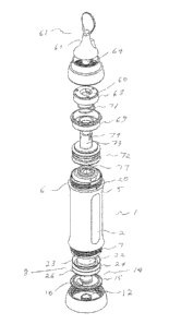
Figure 7D is a top view of the embodiment of figure 7A.
Description of preferred embodiments of the invention
[0041] The embodiments of the feeder 1 that are illustrated in figures !A
to 1G
comprise: a base cap 11, a valve carrier 14, a movable bung 8, a tube 2, a
teat mouthpiece
30 9 and an upper collar 19.
[0042] Although the tube 2 of figures 1A to iF is circular in cross-
section, it may have
any cross-section, so long as that cross-section is substantially constant
throughout its
CA 02928217 2016-04-21
WO 2015/058244 PCT/AU2014/001002
- 9 -
entire length. The tube 2 has upper and lower open ends 3 and 4 and carries
screw threads
6 and 7 adjacent those upper and lower ends. Although the screw threads 6 and
7 of
figures IA to 1(1 are external to the tube 2, those screw threads may be
internal to the tube
2. An over-moulding 5 encases a substantial portion of the exterior surface of
the tube 2
between the upper and lower screw threads 6 and 7. The lower end of the upper
screw
thread 6 terminates in a thread stop 20 to aid in the orientation of
components which are
mounted on that screw thread.
[0043] The tube 2 of figures 1 A to 1.F is symmetrical, in the sense that
the screw
1.0 threads 6 and 7 are identical. According to alternative embodiments of the
invention
which are not illustrated in the drawings, the feeder 1 is constructed so that
it is not
symmetrical in this sense so that the user may identify different "top" and
"bottom" ends.
The identification of different "top" and "bottom" ends of the tube 2 is
useful in the case
where the tube 2 is marked with a scale to indicate the volume of the contents
of the feeder
1.5 1.
[0044] The moveable bung 8 is moveable longitudinally within the tube 2
and
comprises a top 22, an upper blade 23, an intermediate blade 24 and a. lower
blade 26.
Each of the blades 23, 24 and 26 extends around the periphery of the hung 8
and extends
20 radially from the bung 8. The tolerances between the movable bung 8 and
the inner
surfitce of the tube 2 are such as to form a sliding seal between the movable
bung 8 and the
tube 2. The movable bung 8 is preferably constructed of a plastics polymer
with a rubber
over-mould to create a seal and to provide friction with the tube 2. This
friction helps to
support the movable bung 8 from moving downward. The top 22 of the movable
bung 8 is
25 shaped substantially to complement the underside of the teat mouthpiece
9. This helps to
reduce the amount of contents left in the tube 2 when the movable bung 9 has
reached the
top of the tube 2 and. is resting hard up against the underside of the
mouthpiece 9. The
blades 23, 24 and 26 around the movable bung 8 scrape along the inside wall of
the tube 2
as the movable bung 8 moves up towards the mouthpiece 9, leaving virtually
none of the
30 contents behind.
[0045] A base cap 11 is mounted at the lower open end 4 of the tube 2 and
prevents
the movement of the bung 8 out of that end. For this purpose the base cap II
carries an
CA 02928217 2016-04-21
WO 2015/058244
PCT/AU2014/001002
- 10 -
internal screw thread 18 which matches the external screw thread 7 of the tube
2. The
base cap 11 is pierced by a an air hole 12.
[0046] The base cap 11 also retains a valve caffier 14 in place over the
lower open end
4 of the tube 2. The valve carrier 14 has a peripheral region 15, a valve 16
and a pull-tab
10. Preferred forms of the valve 16 include a "dome valve" and a "sphere
valve". As is
illustrated in the drawings, a dome valve (such as valve 16 as is illustrated
in the drawings)
comprises a dome portion the periphery of which is contiguous with a
cylindrical portion.
A sphere valve is not illustrated in the drawings but it comprises a portion
which is
1.0 substantially more than half of a hollow sphere, the periphery of which
is contiguous with
a cylindrical portionõ4 dome valve accordingly has a shallower shape compared
to the
spherical valve. The t7unctional difference between the two valves is that the
spherical
valve is significantly stronger than is the dome valve with regards to back
pressure.
1.5 [0047] The valve 16 is in alignment with the air hole 12 in the
base cap 11. It permits
the ready flow of air from the exterior of tube 2 into the interior of that
tube and
substantially prevents the flow of air in the opposite direction. The air is
then trapped. in
the tube 2 by the One-way valve 16, keeping the bung 8 in place by not
allowing it to fall
downward. The pull-tab 10 enables easy removal of the valve carrier 14, such
as for
20 cleaning. As is shown if figure lit the base cap 11 comprises an outer
peripheral skirt 25
which surrounds the periphery of a central body 30. The periphery of the
central body 30
is formed into longitudinally-running Channels 17.
[0048] An upper collar 19 has an internal screw thread 21 which matches
the external
25 screw thread 6 of the tube 2. The upper collar 19 retains a teat
mouthpiece 9 in place over
the upper open end 3 of the tube 2. The teat mouthpiece 9 has a teat 27 which
projects
outwardly from the mouthpiece base 28 and the peripheral area of the base 28
is gripped
between. the tube 2 and the upper collar 19. The teat 27 is piereed or slit in
the known
manner of teats for baby feeding bottles.
[0049] As is illustrated in figures IC, ID and 1E, it is preferred to
provide a cap 31
which can be placed over the teat mouthpiece 9 for protection and to aid in
the prevention
of spillages. A substantially cylindrical protrusion 32 depends from, the
inner top surface
CA 02928217 2016-04-21
WO 2015/058244 PCT/AU2014/001002
- H -
of the cap 31 to hold an upper region of the teat 27. The cylindrical
protrusion 32 seals off
around the teat to reduce the risk of the spillage of material from the teat.
The cap 31 is
detachably held in place by being an interference fit over the upper collar
19. As is
illustiated in figure 1E, the cap 31 can be stored adjacent the lower end 4 of
the tube. 2 by
retention between the outer skirt 25 and the central body 30 of the base cap
11. The
channels 17 in the central body 30 allow air to flow from the exterior, around
the edge of
the cap 31 and through the air hole 12 into the tube 2.
[0050] As is illustrated in -figures 2A to 2C, it is preferred to provide
a funnel 34 to aid
1.0 in the loading of material into the feeder I. The funnel 34 has a
handle 36 Which protrudes
from the upper periphery of the funnel. It is preferred that the stem 37 of
the funnel be a
close fit within the upper open end 3 of the tube 2.
[0051] The embodiments of the invention that are illustrated in figures
3A to 3G differ
1.5 from the embodiments of figures IA to 1(1 in that the teat mouthpiece 9
has been replaced
by a sipper mouthpiece 41. The sipper mouthpiece 41 is hollow and comprises a
base 42
from which extends a sipper body 43 which is preferably substantially
elliptical in cross-
section and which terminates in a blunt end 44. The blunt end 44 is pierced by
a slit 46
which extends across an axis of that end and operates in the same manner as do
teats for
20 baby feeding bottles.
[0052] The embodiments of the invention that are illustrated in figures
4A to 4G differ
from the embodiments of figures IA to I G in that the teat mouthpiece 9 has
been replaced
by a spout mouthpiece 51. The spout mouthpiece 51 comprises an open-ended
spout 53
25 which extends upwardly from a base 52. A valve 54 in the base 52 allows
for one-way
flow of material from the tube 2 into the spout 53. The purpose the valve 54
is to prevent
contents of the feeder 1 from spilling out when the feeder is on its side or
upside down.
This valve is designed to be weaker than the one-way air valve 16 located in
the movable
bung 8, to enable the contents of the feeder 1 to dispense smoothly.
[0053] The embodiments of the -invention that are illustrated in figures
5A to 5G differ
from the embodiments of figures IA to 1G- in that the teat mouthpiece 9 has
been replaced
bya spoon pump attachment 61,
CA 02928217 2016-04-21
WO 2015/058244
PCT/AU2014/001002
- 12 -
[0054] The spoon pump attachment 61 allows parents to feed their infants
single-
handedly, whilst also promoting utensil education for the infant.
[0055] The spoon pump attachment 61 comprises a spoon 63 and a pump. The
pump
is dimensioned to dispense just enough contents to fill the spoon 63, The
spoon 63
comprises a spoon head 68 and. a spoon tube 64 so that the spoon head 68 is in
communication with the hollow interior of the spoon tube 64. A spoon trigger
67 projects
substantially radially from the spoon tube 64. The pump comprises the top cap
pump pack
1.0 68, the helical spring 71, the pump bung 72 and the pump one way valve
77. The structure
and function of the various components of the of the spoon pump attachment are
as
follows
Spoon top cap 62
1.5 [0056] A spoon top cap 62 snap fits onto the feeder 1, protecting
the spoon 63 when it
is not in use. It can also be clipped into the base cap 11 during use.
Spoon. 63
[0057] The spoon 63 clips onto the top cap pump pack 68. It has a tube 64
that fits
20 into the pump hung 72 and opens onto, the spoon head 66. The contents of
the feeder 1
will travel through the tube 64 onto the spoon head 66. Underneath the tube 64
at the back.
of the spoon head 66 is the spoon trigger 67 where the user applies pressure
to engage the
pump mechanism.
25 Top cap pump pack 68
[0058] A top cap pump pack 68 is fitted to the pump bung 72 with a quick
release
bayonet fitting. The bayonet fitting comprises the bayonet slots 74 in the
pump bung tube
73 and corresponding projections 60 within the top cap pump pack 68. Together
with the
spring stop 69 it houses the spring 71. The top of the pttinp bung 72 and the
tube 64 of the
30 spoon run through the middle of the top cap pump pack 68, spring 71 and
spring stop 69.
Spring 71
CA 02928217 2016-04-21
WO 2015/058244
PCT/AU2014/001002
- i3 -
[0059] The coil spring 71 is fitted to the spring stop 69 and housed in
the top cap
pump pack :68. Its purpose is to return the spoon 63, top cap pump pack 68 and
pump
bung 72 back to its original position.
Spring Stop 69
[0060] The spring stop 69 is fastened to the feeder tube 2 by the pump
collar 68. Its
purpose is to house the spring 71 and attach the pump mechanism to the tube 2.
Pump collar 78
1.0 [0061] The threaded pump collar 78 fastens the spoon pump
attachment 61 to the tube
2. It has an extended collar that reaches above the top cap pump pack 68 to
the base of the
spoon attachment 61 in order to protect the user from pinching skin when
pumping the
spoon attachment 61.
1.5 Pump Bung 72
[0062] The top of the pump bung 72 is a tube 73 that attaches to the top
cap pump
pack 68. The tube 64 of the spoon fits into the tube 73 at the top of the pump
bung 72.
The pump one-way valve 77 clips into the base of the pump bung tube 73. The
pump
bung 72 comprises a body 75 which receives a radially-extending
circumferential seal 76.
20 The outer periphery of the seal 76 forms a sliding seal with the
internal wall of the tube 2.
A radially-extending location/alignment ring 79 is integrally formed with the
body 75
below the circumferential seal 76 and a radially extending scraper/seal blade
80 is
integrally formed with the body 75 below the location/alignment ring 79. The
circumferential seal 76, the location/alignment ring 79 and the scraper/seal
blade 80 result
25 in the pump bung 72 fitting tightly within, and sealing with, the tube
2.
[0063] When downward pressure is applied to the spoon trigger 67, the
pump bung 72
will move downward inside the feeder tube 2. The contents will be force to
squeeze
through the pump one way-valve 77 out through the spoon tube 64 onto the spoon
head
30 66.
CA 02928217 2016-04-21
WO 2015/058244 PCT/AU2014/001002
- 14 -
Pump One-way Valve 77
[0064] The pump one way valve 77 clips into the base of the pump bung
tube 73. The
pump one way valve 77 allows the contents of the feeder 2 to squeeze out onto
the spoon
63, but will not allow the contents to be sucked. back into the tube 2. The
pump one way
valve 77 is designed to be weaker than the one way valve 16 which is fitted at
the bottom
of the feeder. This will allow a smoother feed of the contents dispensing,
rather than a
squirt.
[0065] The embodiments of the invention that are illustrated in figures
7A to 7D differ
1.0 from the embodiments of figures IA to 1G in that the teat mouthpiece 9
has been replaced
by a storage cap 81. The storage cap 81 fits onto the top of the tube 2 and is
held in place
by the upper collar 19. The storage cap 81 is intended tbr use on the tops of
spare feeders
and for the storage of feeders during travel or in refrigerators or in
coolers.
1.5 [0066] The different mouthpieces are designed to accommodate
different textures of
materials. The teat mouthpiece 9 accommodates liquids, such as milk, water and
juices.
The sipper mouthpiece 41 accommodates purees, such as pureed vegetables,
fruits,
cereals, smoothies and yoghurt. The spout mouthpiece Si accommodates mashes,
such as
mashed vegetables, fruits, proteins, and chunky soups.
[0067] The spoon pump attachment: is designed to allow parents to feed
their infants
single-handedly, while also promoting utensil education for the in fain. The
spring-loaded
pump is regulated to dispense just enough contents to fill the attached spoon.
[0068] The presently-described embodiments of the invention are
manufactured in any
suitable material by any suitable process, but particularly preferred
materials and
processes for various components are set out in the following table.
Component Process Material.
1 Tube 2 Injection moulding Tritan copolymter
2 Over-moulding 5 Over moulding ABS (Aciylonitrile
butadiene styrene)
CA 02928217 2016-04-21
WO 2015/058244 PCT/AU2014/001002
- 15 -
3 Bung 8 Injection moulding Polyurethane
4 Teat 9 Injection moulding Silicones
Base cap 1.1 Injection moulding ABS
6 Valve 16 Injection moulding Polyurethane
7 Collar 1.9 Injection moulding ABS
Top cap 31 Injection moulding Tritan copolyester
11 Funnel 34 Injection moulding ABS
12 Sipper mouthpiece 41 Injection moulding Polyurethane
13 Spout mouthpiece 51 Over moulding Polyurethane
14 Spoon 63 Injection moulding Polyurethane
Spring stop 15 Injection moulding ABS
16 Pump Bung 72 Injection moulding HDPE (high-density
polyethylene)
17 Pump one-way valve 77 Injection moulding Polyurethane
18 Pump collar 78 Injection moulding ABS
19 Storage cap Injection moulding ABS
[0069] While the present invention has been described with reference to a
few specific
embodiments, the description is illustrative of the invention and is not to be
construed as
limiting the invention. Various modifications may occur to those skilled in
the. art without
5 departing from the true spirit and scope of the invention as defined by
the appended
claims. As the present invention may be embodied in several forms without
departing
from the spirit of the essential characteristics of the invention, it should
be understood that
the above described embodiments are not to limit the present invention unless
otherwise
specified, but rather should be construed broadly within the spirit and scope
of the
10 invention as defined in the appended claims. The described embodiments are
to be
considered in all respects as illustrative only and not restrictive. Various
modifications
and equivalent arrangements are intended to be included within the spirit and
scope of the
invention and appended claims. Therefore, the specific embodiments are to be
understood
to be illustrative of the many ways in which the principles of the present
invention may be
15 practiced. hi. the following claims, any particular means-plus-tlinction
clauses are
intended to cover structures as performing the defined function and not only
structural
CA 02928217 2016-04-21
WO 2015/058244 PCT/AU2014/001002
- 16 -
equivalents, but also equivalent structures. For example, although a nail and
a screw may
not be structural equivalents in that a nail employs a cylindrical surface to
secure wooden
parts together, whereas a screw employs a. helical surface to secure wooden
parts together,
in the environment of fastening wooden parts, a nail and a screw are
equivalent structures.
[0070] A reference to any prior art in. this specification is not, and
should not be taken
as, an acknowledgment or any form of suggestion that the referenced prior art
forms part
of the common general knowledge in. Australia. Accordingly, it is to be
appreciated that
any discussion of documents, devices, acts or knowledge in this specification
is included
1.0 to explain the context of the present. invention. Further, the
discussion throughout this
specification comes about due to the realisation of the inventor and/or the
identification of
certain related art problems by the inventor. Moreover, any discussion of
material such as
documents, devices, acts or knowledge in this specification is included to
explain the
context of the invention in temis of the inventor's knowledge and experience
and,
1.5 accordingly, any such discussion should not be taken as an admission
that any of the
material forms part of the prior art base or the common general knowledge in
the relevant
art. in Australia, or elsewhere, on or before. the priority date of the
disclosure and claims
herein.
20 [0071] Throughout this specification the use of the word "inventor"
in singular form
may be taken as reference to one (singular) inventor or more than one (plural)
inventor of
the present invention.
[0072] Throughout this specification, the words "comprise", "comprised",
25 "comprising" and "comprises" are to be taken to specify the presence of
stated features,
integers, steps or components but does not preclude the presence or addition
of one or
more other features, integers, steps, components or groups thereof,
[0073] In the claims, each dependent claim is to be read as being within
the scope of
30 its parent claim or claims, in the sense that a dependent Claim is not
to be interpreted as
infringed unless its parent claims are also infringed.