Sélection de la langue

Search

Sommaire du brevet 2948318 

Énoncé de désistement de responsabilité concernant l'information provenant de tiers

Une partie des informations de ce site Web a été fournie par des sources externes. Le gouvernement du Canada n'assume aucune responsabilité concernant la précision, l'actualité ou la fiabilité des informations fournies par les sources externes. Les utilisateurs qui désirent employer cette information devraient consulter directement la source des informations. Le contenu fourni par les sources externes n'est pas assujetti aux exigences sur les langues officielles, la protection des renseignements personnels et l'accessibilité.

Disponibilité de l'Abrégé et des Revendications

L'apparition de différences dans le texte et l'image des Revendications et de l'Abrégé dépend du moment auquel le document est publié. Les textes des Revendications et de l'Abrégé sont affichés :

  • lorsque la demande peut être examinée par le public;
  • lorsque le brevet est émis (délivrance).
(12) Brevet: (11) CA 2948318
(54) Titre français: METHODE DE PRODUCTION ET DE REVETEMENT D'UNE LENTILLE
(54) Titre anglais: METHOD FOR PRODUCING AND COATING A LENS
Statut: Octroyé
Données bibliographiques
(51) Classification internationale des brevets (CIB):
  • B29D 11/00 (2006.01)
  • G02B 1/10 (2015.01)
  • C09K 3/10 (2006.01)
(72) Inventeurs :
  • PIOTROWSKI, DANIEL (Suisse)
  • ULRICH, RENE JOSEF (Suisse)
(73) Titulaires :
  • INTERGLASS TECHNOLOGY AG (Suisse)
(71) Demandeurs :
  • INTERGLASS TECHNOLOGY AG (Suisse)
(74) Agent: BORDEN LADNER GERVAIS LLP
(74) Co-agent:
(45) Délivré: 2023-06-13
(22) Date de dépôt: 2016-11-14
(41) Mise à la disponibilité du public: 2017-05-19
Requête d'examen: 2021-11-04
Licence disponible: S.O.
(25) Langue des documents déposés: Anglais

Traité de coopération en matière de brevets (PCT): Non

(30) Données de priorité de la demande:
Numéro de la demande Pays / territoire Date
1688/15 Suisse 2015-11-19

Abrégés

Abrégé français

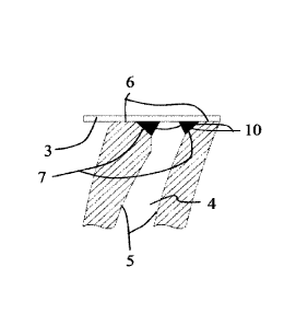
Il est décrit une méthode de fabrication et de revêtement dune lentille qui comprend lapplication dune pâte polymérisable le long du bord dune première coque de moulage et le long du bord de la deuxième coque de moulage, la liaison des deux coques de moulage au moyen dun élément détanchéité pour former une unité, la coulée dun monomère dans lunité, le durcissement du monomère et de la pâte de manière à former la lentille, le dégagement de lélément détanchéité de lunité, la séparation de la lentille des deux coques de moulage, la disposition de la lentille dans une chambre à vide dune installation de dépôt de revêtement sous vide, et le revêtement dune surface optique de la lentille, aucun processus de lavage nétant effectué entre létape de séparation de la lentille des deux coques de moulage et létape de disposition de la lentille (8) dans la chambre à vide.


Abrégé anglais

A method for producing and coating a lens comprises: applying a curable paste along the edge of a first moulding shell and along the edge of the second moulding shell, connecting the two moulding shells by means of a sealing element to form a unit, casting a monomer into the unit, curing the monomer and the paste so that the lens is formed, detaching the sealing element from the unit, separating the lens from the two moulding shells, placing the lens in a vacuum chamber of a vacuum-coating installation, and coating an optical surface of the lens, wherein no washing process is carried out between the step of separating the lens from the two moulding shells and the step of placing the lens (8) in the vacuum chamber.

Revendications

Note : Les revendications sont présentées dans la langue officielle dans laquelle elles ont été soumises.


6
CLAIMS
1. Method for producing and coating a lens, comprising the following steps:
applying a curable paste (10) along the edge of a first moulding shell (1) and
along the edge of the
second moulding shell (2),
connecting the two moulding shells (1, 2) by means of a sealing element (3) to
form a unit,
casting a monomer into the unit,
curing the monomer and the paste (10) so that the lens (8) is formed,
detaching the sealing element (3) from the unit,
separating the lens (8) from the two moulding shells (1, 2),
placing the lens (8) in a vacuum chamber of a vacuum-coating installation, and
coating an optical surface of the lens (8), wherein no washing process is
carried out between the
step of separating the lens (8) from the two moulding shells (1, 2) and the
step of placing the lens (8) in
the vacuum chamber.
2. Method according to claim 1, wherein the paste (10) consists of a
material which has a sufficiently
high viscosity so that the paste (10) applied to the moulding shells does not
trail away, does not gas out
and connects to the monomer or the lens (8) during curing and is rubber-like
in the cured state.

Description

Note : Les descriptions sont présentées dans la langue officielle dans laquelle elles ont été soumises.


CA 02948318 2016-11-14
1
Method for producing and coating a lens
FIELD OF THE INVENTION
[0001] The invention relates to a method for producing and coating a lens, in
which the lens is
produced by casting and is subsequently coated in a vacuum-coating
installation.
BACKGROUND OF THE INVENTION
100021 Such a lens is a semi-finished product, from which subsequently a
spectacle lens is cut out and
fitted into a spectacle frame, for example by an optician.
[0003] Methods for producing a lens by casting are known for example from US
4251474 and
WO 02/087861. In this production method, a monomer is cast into a cavity
bounded by two moulding
shells and a seal and is polymerised therein, so that in doing so the lens is
created. The seal is then
removed and the lens is separated from the two moulding shells. The lens can
then be provided with
optical layers, e.g. with antireflection layers, anti-scratch layers etc, in
immersion baths or in a vacuum-
coating installation such as a PECVD installation.
[0004] The cast lenses mostly have a protruding projection along their
circumference which is brittle
and can therefore easily be damaged. In order to ensure that detached
splinters do not reach the optical
surface of the lens during the subsequent coating by means of a process in
which the layers are applied in
a vacuum-coating installation, the lenses need to be cleaned in one or several
washing processes prior to
placement in the vacuum chamber.
SUMMARY OF THE INVENTION
[0005] It is an object of the invention to improve the production and coating
of lenses.
[0006] A method for producing and coating a lens according to the invention
comprises the following
steps:
applying a curable paste along the edge of a first moulding shell and along
the edge of the second
moulding shell,
connecting the two moulding shells by means of a sealing element to form a
unit,
casting a monomer into the unit,
curing the monomer and the paste so that the lens is formed,
detaching the sealing element from the unit,
separating the lens from the two moulding shells,
placing the lens in a vacuum chamber of a vacuum-coating installation, and
coating an optical surface of the lens, wherein no washing process is carried
out between the step

CA 02948318 2016-11-14
2
of separating the lens from the two moulding shells and the step of placing
the lens in the vacuum
chamber.
[0007] Preferably, the paste meets the following criteria: The paste consists
of a material which has a
sufficiently high viscosity so that the paste applied to the moulding shells
does not trail away, does not
gas out and connects to the monomer or the lens during curing and is rubber-
like in the cured state.
BRIEF DESCRIPTION OF THE DRAWING FIGURES
[0008] The accompanying drawings, which are incorporated into and constitute a
part of this
specification, illustrate one or more embodiments of the present invention
and, together with the detailed
description, serve to explain the principles and implementations of the
invention. For the sake of clarity,
the figures are not drawn to scale.
[0009] In the drawings:
Fig. 1 shows two mutually opposite moulding shells, which are
connected to form a unit by
means of a sealing element;
Fig. 2 shows an enlarged sectional view of Fig. 1;
Fig. 3 shows a moulding shell with a chamfer;
Fig. 4 shows a lens;
Fig. 5 shows an enlarged sectional view of Fig. 4;
Fig. 6 shows a moulding shell in a top view, along the edge of
which a paste has been
applied;
Fig. 7 shows the unit in a cross-sectional view, and
Fig. 8 shows a sectional view of the lens produced by means of the
method in accordance
with the invention.
DETAILED DESCRIPTION OF THE INVENTION
[0010] Fig. 1 shows two mutually opposite moulding shells 1 and 2, which are
connected to form a
unit by means of a sealing element 3. The sealing element 3 is preferably a
tape. The sealing element 3
can also be an element known in the field as a "gasket", which consists of
rubber or a rubber-like
material. The two moulding shells 1 and 2 and the sealing element 3 delimit a
cavity 4. The two
moulding shells 1 and 2 contain a surface facing the cavity 4, which will be
referred to below as the
optical surface 5, because these two surfaces 5 delimit the surfaces of the
lens to be produced. Fig. 2
shows an enlarged sectional view of the portion of Fig. 1 which is marked by a
circle. The illustration
shows that the transition from the side edges 6 to the optical surfaces 5 in
the two moulding shells 1 and
2 is formed by a chamfer 7. The transition is thus chamfered. Fig. 3 shows the
surface 5 of the moulding
shell 1 facing the cavity 4, wherein the chamfer 7 is shown in a broader way
for reasons of clarity of the

CA 02948318 2016-11-14
3
illustration.
100111 As shown in Fig. 4, the lens 8 produced by means of such a unit
contains along its edge on both
sides a respective projection corresponding to the chamfers 7 of the moulding
shells 1 and 2. Fig. 5
shows an enlarged sectional view of Fig. 4. Since the cured material from
which the lens 8 is produced is
relatively brittle, splinters repeatedly break away from the projections 9
during the subsequent machining
steps. The lens 8 must therefore be washed carefully in order to remove any
splinters prior to coating by
means of a vacuum-coating method in which the coating of coatings is/are
applied in a vacuum chamber.
[0012] The method which will be described below in closer detail produces a
lens which has such a
projection, but said projection consists of a rubber-like and therefore non-
brittle material, so that there is
no risk that splinters will break off. For this reason, it is possible to omit
one or several washing
processes prior to the introduction of the lens into the vacuum chamber of the
coating system.
[0013] The method in accordance with the invention for producing a lens by
casting and coating the
lens by means of a vacuum-coating method comprises the following steps:
1. Applying a curable paste 10 along the edge of the first moulding shell 1
and along the edge of
Is the second moulding shell 2.
[0014] Fig. 6 shows a top view and an illustration not true to scale of the
first moulding shell 1 with
the applied paste 10, wherein the paste 10 is shown in a broader way for
reasons of clarity of the
illustration. The paste 10 is situated at the transition point between the
optical surface 5 and the side edge
6, i.e. on the chamfer 7 (Fig. 2). The paste 10 is applied for example in that
the moulding shell 1 rotates
and the paste is supplied by means of a syringe that can be pressurised. The
paste 10 can be spread by
means of a doctor blade if necessary in such a way that the paste 10
completely covers the chamfer 7.
2. Connecting the two moulding shells 1 and 2 by means of a sealing element 3
to form a unit.
[0015] Fig. 7 shows an enlarged sectional view of the unit in a cross-
sectional view. The paste 10 is
dimensioned and distributed in such a way that the monomer is unable to flow
past the paste 10 during
pouring.
3. Pouring the monomer into the unit.
4. Curing the monomer and the paste 10.
[0016] The curing is a process in which the monomer polymerises, wherein the
lens 8 is formed. The
paste 10 preferably consists of a material which cures when the monomer is
polymerised. The curing of
the monomer and the paste 10 can occur in this case in a single step. It is
alternatively possible to cure in

CA 02948318 2016-11-14
4
two steps at first the paste 10 and then the monomer, or vice versa. The
curing of monomer and paste 10
preferably occurs by means of UV radiation, but can also occur in a different
way, e.g. by heat in a
furnace.
5. Detaching the sealing element 3 from the unit.
6. Separating the lens 8 from the two moulding shells 1 and 2.
[0017] Corresponding to the chamfers 7 of the two moulding shells 1 and 2, the
lens 8 has two
protruding projections 9 along its side edge 6, as shown in Fig. 8. The two
projections 9 consist of the
cured material of paste 10 however.
7. Placing the lens 8 in the vacuum chamber of a vacuum-coating installation,
and
8. Applying one or more optical layers on at least one of the two optical
surfaces of the lens 8,
wherein no washing process is carried out between the step of separating the
lens 8 from the
two moulding shells 1 and 2 and the step of placing the lens 8 in the vacuum
chamber.
[0018] Possible vacuum-coating methods are CVD (chemical vapor deposition)
methods, especially
the PECVD (plasma-enhanced chemical vapor deposition) method and the PACVD
(plasma-assisted
chemical vapor deposition) method, as well as different PVD (physical vapor
deposition) methods, which
include for example sputtering, electron beam evaporation, and the pulsed
laser deposition (PLD)
method. This list is not exhaustive.
[0019] The paste 10 consists of a material which meets the following
requirements:
- It is curable.
- It has a sufficiently high viscosity so that the paste 10 applied to the
chamfer 7 does not trail way.
- It does not gas out so that no mist can be formed which could deposit on
the moulding shells 1 and 2,
which could lead to optical defects of the lens 8.
- During curing, it connects to the monomer or the lens 8, respectively,
so that during the separation of
the lens 8 from the two moulding shells 1 and 2 it detaches from the moulding
shells 1 and 2 together
with the lens 8.
- It is rubber-like in the cured state.
[0020] Materials which meet these requirements are distributed, for example,
by the company Dymax
under the trade name "Speedmask". These materials are "light curable temporary
masking resins".
[0021] The projections 9 of the lens 8 produced by this method are rubber-
like. Accordingly, there is
no risk that splinters will break off.

CA 02948318 2016-11-14
[0022] While embodiments and applications of this invention have been shown
and described, it would
be apparent to those skilled in the art having the benefit of this disclosure
that many more modifications
than mentioned above are possible without departing from the inventive concept
described herein. The
invention, therefore, is not to be restricted except in the spirit of the
appended claims and their
5 equivalents.

Dessin représentatif
Une figure unique qui représente un dessin illustrant l'invention.
États administratifs

Pour une meilleure compréhension de l'état de la demande ou brevet qui figure sur cette page, la rubrique Mise en garde , et les descriptions de Brevet , États administratifs , Taxes périodiques et Historique des paiements devraient être consultées.

États administratifs

Titre Date
Date de délivrance prévu 2023-06-13
(22) Dépôt 2016-11-14
(41) Mise à la disponibilité du public 2017-05-19
Requête d'examen 2021-11-04
(45) Délivré 2023-06-13

Historique d'abandonnement

Il n'y a pas d'historique d'abandonnement

Taxes périodiques

Dernier paiement au montant de 203,59 $ a été reçu le 2022-11-07


 Montants des taxes pour le maintien en état à venir

Description Date Montant
Prochain paiement si taxe applicable aux petites entités 2023-11-14 100,00 $
Prochain paiement si taxe générale 2023-11-14 277,00 $

Avis : Si le paiement en totalité n'a pas été reçu au plus tard à la date indiquée, une taxe supplémentaire peut être imposée, soit une des taxes suivantes :

  • taxe de rétablissement ;
  • taxe pour paiement en souffrance ; ou
  • taxe additionnelle pour le renversement d'une péremption réputée.

Les taxes sur les brevets sont ajustées au 1er janvier de chaque année. Les montants ci-dessus sont les montants actuels s'ils sont reçus au plus tard le 31 décembre de l'année en cours.
Veuillez vous référer à la page web des taxes sur les brevets de l'OPIC pour voir tous les montants actuels des taxes.

Historique des paiements

Type de taxes Anniversaire Échéance Montant payé Date payée
Le dépôt d'une demande de brevet 200,00 $ 2016-11-14
Taxe de maintien en état - Demande - nouvelle loi 2 2018-11-14 50,00 $ 2018-11-01
Taxe de maintien en état - Demande - nouvelle loi 3 2019-11-14 50,00 $ 2019-11-05
Taxe de maintien en état - Demande - nouvelle loi 4 2020-11-16 100,00 $ 2021-04-22
Surtaxe pour omission de payer taxe de maintien en état pour demande 2021-04-22 150,00 $ 2021-04-22
Requête d'examen 2021-11-15 408,00 $ 2021-11-04
Taxe de maintien en état - Demande - nouvelle loi 5 2021-11-15 204,00 $ 2021-11-10
Taxe de maintien en état - Demande - nouvelle loi 6 2022-11-14 203,59 $ 2022-11-07
Taxe finale 153,00 $ 2023-04-06
Titulaires au dossier

Les titulaires actuels et antérieures au dossier sont affichés en ordre alphabétique.

Titulaires actuels au dossier
INTERGLASS TECHNOLOGY AG
Titulaires antérieures au dossier
S.O.
Les propriétaires antérieurs qui ne figurent pas dans la liste des « Propriétaires au dossier » apparaîtront dans d'autres documents au dossier.
Documents

Pour visionner les fichiers sélectionnés, entrer le code reCAPTCHA :


Pour visualiser une image, cliquer sur un lien dans la colonne description du document. Pour télécharger l'image (les images), cliquer l'une ou plusieurs cases à cocher dans la première colonne et ensuite cliquer sur le bouton "Télécharger sélection en format PDF (archive Zip)" ou le bouton "Télécharger sélection (en un fichier PDF fusionné)".

Liste des documents de brevet publiés et non publiés sur la BDBC .

Si vous avez des difficultés à accéder au contenu, veuillez communiquer avec le Centre de services à la clientèle au 1-866-997-1936, ou envoyer un courriel au Centre de service à la clientèle de l'OPIC.


Description du
Document 
Date
(yyyy-mm-dd) 
Nombre de pages   Taille de l'image (Ko) 
Requête d'examen 2021-11-04 6 232
Lettre du bureau 2022-04-11 2 190
Demande d'examen 2022-09-14 4 154
Modification 2022-12-29 6 164
Dessins 2022-12-29 3 48
Taxe finale 2023-04-06 3 79
Dessins représentatifs 2023-05-11 1 8
Page couverture 2023-05-11 1 38
Abrégé 2016-11-14 1 16
Description 2016-11-14 5 196
Revendications 2016-11-14 1 23
Dessins 2016-11-14 3 31
Page couverture 2017-06-06 2 41
Nouvelle demande 2016-11-14 5 115
Dessins représentatifs 2017-04-21 1 7
Certificat électronique d'octroi 2023-06-13 1 2 527