Note : Les descriptions sont présentées dans la langue officielle dans laquelle elles ont été soumises.
QUICK ADJUST POWER ADJUSTER FOR A SEAT WITH A TUBULAR LEAD
SCREW
[0001]
BACKGROUND OF THE INVENTION
1. Field of the Invention
[0002] The invention relates to a quick adjust power adjuster for a seat
track of
an automotive vehicle seat assembly. More particularly, the invention relates
to a quick
adjust power adjuster having a tubular lead screw for selectively providing
either
powered or manual fore and aft movement of the seat assembly along a floor of
an
automotive vehicle
2. Description of Related Art
[0003] Automotive vehicles include seat assemblies for supporting seat
occupants
within a passenger compartment of the vehicle. Typically, the seat assemblies
include a
generally horizontal seat cushion spaced above a floor of the vehicle and a
generally
vertical or upright seat back. The seat back is commonly operatively coupled
to the seat
cushion to allow for selective pivotal adjustment of the seat back relative to
the seat
cushion between a plurality of reclined seating positions. Many seat
assemblies also
include a seat track assembly coupled between the seat cushion and the floor
to provide
fore and aft movement of the seat assembly within the vehicle. Typically, the
seat track
assembly includes a lower track fixedly secured to the floor of the vehicle
and an upper
track slidably engaging the lower track. The upper track is fixedly secured to
a bottom
surface of the seat cushion to allow for sliding movement of the seat assembly
along the
lower track. It is well known in the vehicle seating art to provide a power
seat track
assembly driven by an electric motor for moving the upper track, and thus the
seat
assembly, relative to the lower track. Many such power seat track assemblies
include a
conventional gearbox or drive assembly operatively coupled in a longitudinal
channel
1
Date Recue/Date Received 2020-10-09
CA 02951874 2016-12-16
between the upper and lower tracks for converting rotational input of the
motor into
linear movement of the seat assembly. Several such examples are described in
U.S. Pat.
Nos. 8,226,063; 6,915,998; 6,575,421; 6,260,922; 5,816,555; 5,314,158; and
4,790,202.
Typically, a threaded lead screw is fixedly secured to the lower track and the
gearbox is
operatively coupled between the lead screw and the upper track. The gearbox or
drive
assembly includes a housing having through holes or bores that are offset 90
degrees to
align and retain a worm and a gear or worm wheel. The gear includes a threaded
internal
bore for threadably engaging the lead screw and a geared outer surface for
meshing with
the worm. In an arrangement of this kind, the worm is driven by a shaft
extending from
the motor which in turn causes the gear to rotate. Rotation of the gear causes
the gear to
move in a longitudinal direction along the fixed lead screw which leads to the
desired
movement of the upper track relative to the lower track.
[0004] However, the motor and drive assembly only provides powered fore and
aft movement of the upper track relative to the lower track, and hence, the
sliding fore
and aft adjustment of the seat assembly. It is often desirable to quickly and
manually
move the seat assembly from a passenger fore/aft adjusted position to a full
forward easy
entry position wherein the upper track is moved forward along the lower track
to a
forward most position therebetween to allow easy access and entry into the
vehicle
behind the seat assembly. Further, it is also desirable to maintain or
remember the
passenger fore/aft adjusted position during fore and aft movement of the seat
assembly to
the full forward easy entry position.
SUMMARY OF THE INVENTION
[0005] According to one aspect of the invention, a power adjuster is
provided for
adjusting the position of an upper track relative to a lower track of a seat
track assembly.
An elongated guide rod extends axially between opposite first and second ends
and is
adapted to be fixedly secured to the lower track. A tubular lead screw extends
axially
between fore and aft ends and is slidably coupled to the guide rod. A driven
assembly is
operatively coupled to the tubular lead screw for axial travel along the
tubular lead screw
between the fore and aft ends in response to rotation of the driven assembly.
A drive
assembly is adapted to be fixedly coupled to the upper track and operatively
coupled to
2
CA 02951874 2016-12-16
the driven assembly for selectively rotating the driven assembly in opposite
first and
second directions for axial travel along the tubular lead screw. A release
mechanism is
adapted to be coupled to the lower track and operable between a locked
condition
coupled to the tubular lead screw to prevent sliding movement of the tubular
lead screw
along the guide rod wherein the driven assembly and the drive assembly move
axially
along the lead screw to slide the upper track relative to the lower track in a
power
operation mode; and an unlocked condition decoupled from the tubular lead
screw to
allow sliding movement of the tubular lead screw along the guide rod while the
driven
assembly and the drive assembly remain axially fixed to the tubular lead screw
to slide
the upper track relative to the lower track in a manual operation mode.
BRIEF DESCRIPTION OF THE DRAWINGS
[0006] Advantages of the present invention will be readily appreciated as
the
same becomes better understood by reference to the following detailed
description when
considered in connection with the accompanying drawings wherein:
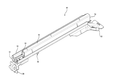
[0007] Figure 1 is a perspective view of the seat track assembly and quick
adjust
power adjuster according to a preferred embodiment of the invention;
[0008] Figure 2 is a perspective view of the lower track of the seat track
assembly and the quick adjust power adjuster in a locked condition with the
seat track
assembly in a passenger fore/aft adjusted position;
[0009] Figure 3 is a perspective view of the lower track of the seat track
assembly and the quick adjust power adjuster in an unlocked condition; and
[00101 Figure 4 is a perspective view of the lower track of the seat track
assembly and the quick adjust power adjuster with the seat track assembly in
the full
forward, easy entry position.
DETAILED DESCRIPTION OF THE EMBODIMENTS
[0011] Referring to the Figures, wherein like numerals indicate like or
corresponding parts throughout the several views, a seat track assembly 10 is
generally
3
CA 02951874 2016-12-16
shown in the Figures for providing both power and manual sliding fore and aft
movement of a seat assembly (not shown) in an automotive vehicle (not shown).
The
seat track assembly 10 extends longitudinally between opposite fore and aft
ends 12, 14
and includes a generally inverted U-shaped upper track 16 slidably and
matingly coupled
to a generally U-shaped lower track 18 for providing fore and aft sliding
movement of
the upper track 16 relative to the lower track 18, as is commonly known in the
art. The
upper track 16 is adapted to be fixedly secured to the bottom side of a seat
cushion of the
seat assembly and the lower track 18 is adapted to be fixedly secured to the
floor of the
automotive vehicle by one or more mounting risers 20, 22. The upper and lower
tracks
16, 18 define a longitudinal internal channel 24 thcrebeween extending between
the fore
and aft ends 12, 14. It should be appreciated that an automotive seat assembly
includes a
pair of parallel and spaced apart seat track assemblies 10 mounted between the
bottom of
the seat assembly and the floor of the vehicle for providing fore and aft
sliding
adjustment of the seat assembly within the vehicle as is commonly known in the
art.
[0012] Referring to
Figure 2, the scat track assembly 10 is shown with the upper
track 16 removed from the lower track 18. A quick adjust power adjuster 30,
hereinafter
power adjuster, is operatively coupled between the upper track 16 and lower
track 18 for
selectively providing either power or manual fore and aft sliding movement of
the upper
track 16 relative to the lower track 18. The power adjuster 30 includes a
drive assembly
32, a driven assembly 34, and a release mechanism 36. The power adjuster 30 is
disposed within the channel 24 and is operatively coupled between the upper
track 16
and lower track 18. 'The power adjuster 30 drives the upper track 16
longitudinally, or
linearly, fore and aft relative to the lower track 18 in response to rotary
input by an
electric motor (not shown) as is commonly known in the art. The drive assembly
32
includes a housing 38 having a lateral through bore with an open bottom slot
for
rotatably supporting a worm gear 40 therein. The drive assembly 32 further
includes a
generally U-shaped retainer strap 42 for supporting the housing 38 and fixedly
securing
the drive assembly 32 to the upper track 16. The retainer strap 42 includes
longitudinally
spaced apart upright portions 44, 46. The upright portion 44 extends into a
first
horizontal top portion 48 fixedly secured to the upper track 16 and the
upright portion 46
extends into a second horizontal top portion 50 facing opposite the first top
portion 48
4
of the upright portions 44, 46 further include an axial aligned hole 52. The
drive assembly
32 further includes an elongated, hollow tubular lead screw 54 extending
axially between
opposite fore and aft ends 56, 58. The tubular lead screw 54 includes an
external helical
thread 60 and an internal profile-shaped through bore 62. The profile shape of
the through
bore 62 may be hex-shaped or D-shaped when viewed in cross-section, however,
it should
be appreciated that the shape may vary as desired.
[0013] The lower track 18 includes a pair of mounting flanges 64, 66
projecting
upwardly therefrom adjacent opposing respective fore and aft ends 12, 14 of
the lower
track 18. An elongated, rigid and cylindrical guide rod 70 extends
longitudinally between
and is fixedly coupled to the respective fore and aft mounting flanges 64, 66.
The guide
rod 70 includes a profile-shaped outer surface 72, such as a hex-shape or D-
shape when
viewed in cross-section, corresponding to the profile shape of the through
bore 62. The
tubular lead screw 54 is slidably journaled to the guide rod 70 between the
opposite ends
thereof. More specifically, the shape of the outer surface 72 of the guide rod
70 is
corresponding or keyed to match the shape of the through bore 62 of the
tubular lead screw
54 to allow axial sliding movement of the tubular lead screw 54 along the
guide rod 70
while preventing rotation of the tubular lead screw 54 relative to the guide
rod 70. The
tubular lead screw 54 also includes a locking lug 74 fixedly secured to the
fore end 56
thereof. The locking lug 74 includes a collar portion 76 and a radial flange
portion 78
defining an abutment wall adjacent the fore end 56 of the tubular lead screw
54.
[0014] The driven assembly 34 includes a driven gear 80 supported
between the
upright portions 44, 46 of the retainer strap 42 and having an external
helical thread in
meshed engagement with the worm gear 40 and an internal helical thread in
meshed
engagement with the helical thread 60 of the tubular lead screw 54.
[0015] The drive assembly 32 drives the upper track 16 longitudinally,
or linearly,
fore and aft relative to the lower track 18 in response to rotary input by an
electric drive
motor (not shown) as is commonly known in the art. That is, an electric drive
motor (not
shown) drives and rotates the worm gear 40 to rotatably drive the driven gear
80. The
driven gear 80 rotates about the tubular lead screw 54 and travels axially
along tubular
Date recu/Date Received 2020-04-14
lead screw 54 thereby automatically sliding the upper track 16 fore and aft
relative to the
lower track 18.
[0016] The tubular lead screw 54 is shown in a home position in Figure 2
positioned along the guide rod 70 adjacent the aft end 14 of the lower track
18 which
provides for power fore/aft adjustment of the seat track assembly 10 as will
be further
described. The release mechanism 36 includes a quick adjust latch 82
operatively coupled
to the lower track 18 for selective engagement with the locking lug 74 between
a locked
condition, as shown in Figure 2, retaining the lead screw tubular 54 in the
home position
and an unlocked condition, as shown in Figure 3, allowing the tubular lead
screw 54 to
slide longitudinally along the guide rod 70. More specifically, the quick
adjust latch 82
includes a latch arm 84 pivotally coupled to the bottom of the lower track 18
by pivot 86.
A pair of spaced apart latch prongs 88, 90 extend from the latch arm 84 and
project through
an opening 92 formed in the bottom of the lower track 18. A biasing spring 94,
such as a
clock spring, is operatively coupled between the latch arm 84 and the lower
track 18 for
biasing the quick adjust latch 82 to pivot to the locked condition wherein the
latch prongs
88, 90 extends through the opening 92 and around opposing sides of the collar
portion 76
of the locking lug 74 against the abutment wall of the flange portion 78 to
prevent sliding
movement of the tubular lead screw 54 along the guide rod 70 and retain the
tubular lead
screw 54 in the home position. A Bowden type push-pull cable 96, or other type
of
actuator, is connected to the quick adjust latch 82 for actuating and pivoting
the latch 82
to the unlocked condition releasing the latch prongs 88, 90 from the locking
lug 74 and
spaced below the opening 92 in the lower track 18 allowing the tubular lead
screw 54 to
slide longitudinally along the guide rod 70 towards the fore end 12 of the
lower track 18.
[0017] In operation, the seat track assembly 10 is shown in a fore/aft
seat adjusted
position for seat occupant comfort in Figures 1 and 2. The release mechanism
36 of the
power adjuster 30 is in the locked condition with the latch prongs 88, 90 of
the quick adjust
latch 82 extending through the opening 92 in the lower track 18 and
6
Date recu/Date Received 2020-04-14
CA 02951874 2016-12-16
engaged with the locking lug 74 against the flange portion 78 to prevent
sliding
movement of the tubular lead screw 54 along the guide rod 70. With the release
mechanism 36 in the locked condition, the electric motor may be actuated to
rotate the
worm gear 40 of the drive assembly 32 in first or second rotational directions
as is
commonly known in the art. It should be appreciated that the electric motor
may have an
output drive shaft connected directly to the worm gear 40 or have a cable or
other
flexible shaft extending between and interconnecting the output shaft of the
electric
motor with the worm gear 40. Rotation of the worm gear 40 in a first
rotational direction
causes rotation of the driven gear 80. The meshed engagement of the driven
gear 80
with the helical thread 60 of the tubular lead screw 54 causes the driven gear
80, and thus
the driven assembly 34, to travel longitudinally along the tubular lead screw
54 between
the fore and aft ends 56, 58. The keyed corresponding and mating profile shape
of the
through bore 62 of the tubular lead screw 54 with the outer surface 72 of the
guide rod
70 prevents the tubular lead screw 54 from rotating about the guide rod 70.
Since the
drive assembly 32 and driven assembly 34 are coupled to the upper track 16 by
the
retainer strap 42, the drive assembly 32 and driven assembly 34 force the
upper track 16
to move longitudinally fore and aft along the lower track 18 in a powered
operation
mode for seat occupant adjustment of the seat track assembly 10 and automotive
seat
within the vehicle.
[0018] Referring to
Figures 3 and 4, the cable 96 may be pulled to actuate and
pivot the release mechanism 36 to the unlocked condition with the latch prongs
88, 90
released from engagement with the locking lug 74 and moved below the opening
92 in
the lower track 18. In the unlocked condition, the drive assembly 32 and
driven
assembly 34 remain coupled with the tubular lead screw 54. However, with the
release
mechanism 36 in the unlocked condition decoupled from the tubular lead screw
54,
referred to as the manual operation mode, the upper track 16 is free to move
longitudinally fore and aft along the lower track 18 without actuation of the
electric
motor or drive assembly 32 from the seat adjusted position to a forward-most
position
along the lower track 18, defined as an easy entry position, as shown in
Figure 4 to allow
access behind the seat assembly within the vehicle. That is, with the release
mechanism
36 in the unlocked condition and the quick adjust latch 82 decoupled from
engagement
7
CA 02951874 2016-12-16
with the locking lug 74 of the tubular lead screw 54, the tubular lead screw
54 is free to
slide longitudinally along the guide rod 70 from the home position shown in
Figure 3 to
the fore end of the guide rod 70 adjacent the fore end 12 of the lower track
18 as shown
in Figure 4, defining the easy entry position. As also shown in Figure 4, the
drive
assembly 32 and driven assembly 34 are fixedly secured to the upper track 16
and in
meshed engagement with the tubular lead screw 54, and therefore travel fore
and aft with
the upper track 16 relative to the lower track 18. Additionally, with the
driven assembly
34 coupled with the tubular lead screw 54, the driven assembly 34 maintains
its
previously adjusted position along the tubular lead screw 54 to maintain a
memory
position of the previous fore/aft seat adjusted position of Figures 1 and 2.
[0019] Finally, the seat track assembly 10 may be manually returned from
the
easy entry position to the fore/aft seat adjusted position by manually sliding
the upper
track 16 longitudinally along the lower track 18 until the tubular lead screw
54 is
returned to the home position along the guide rod 70 shown in Figure 3. Upon
return to
the home position, the release mechanism 36 returns to the locked condition
with the
latch prongs 88, 90 of the quick adjust latch 82 extending through the opening
92 in the
lower track 18 and engaging with the flange portion 78 of the locking lug 74
to prevent
further sliding movement of the tubular lead screw 54 along the guide rod 70
and allow
for continued use in the power operation mode as previously described.
[0020] The invention has been described in an illustrative manner, and it
is to be
understood that the terminology, which has been used, is intended to be in the
nature of
words of description rather than of limitation. Many modifications and
variations of the
present invention are possible in light of the above teachings. It is,
therefore, to be
understood that within the scope of the appended claims, the invention may be
practiced
other than as specifically described.
8