Note : Les descriptions sont présentées dans la langue officielle dans laquelle elles ont été soumises.
- 1 -
TITLE
PENDENT RESIDENTIAL
FIRE PROTECTION SPRINKLERS
RELATED APPLICATION
This application claims benefit under 35 U.S.C. 119(e) of U.S. Provisional
Patent Application
No. 60/954,072, filed on August 6, 2007.
BACKGROUND OF THE INVENTION
Field of the Invention
[0001] Our invention relates to pendent residential fire protection
sprinklers, and more
particularly, relates to pendent residential fire protection sprinklers
suitable for the protection of
relatively large residential spaces, by providing the required coverage of a
large space with the
required uniformity and required throughput (i.e., flow, measured, e.g., in
gallons per minute) at
CA 2952253 2018-04-20
- 2 -
relatively low water pressures. The invention also relates to residential fire
protection systems
utilizing such pendent residential fire protection sprinklers.
Related Art
[0002] Fire protection sprinklers are conventionally connected to a conduit to
receive a
pressurized fire-extinguishing fluid, such as water. A typical fire protection
sprinkler has a base
portion with a threaded portion for connection to the conduit, and an output
orifice to output the
fire-extinguishing fluid to provide fire control and/or suppression. The
output orifice is sealed by
a seal cap that is held in place by a release mechanism. The release mechanism
is designed to
release the seal cap under predetermined conditions, thereby initiating the
flow of the fire-
extinguishing fluid. A typical release mechanism includes a thermally-
responsive element, e.g., a
frangible bulb, and may include a latching mechanism.
[0003] Certain conventional fire protection sprinklers have a pair of arms
that extend from the
base portion and meet at a hub portion to form a frame. The hub portion is
spaced apart from the
output orifice of the base portion and lies on the longitudinal axis thereof
(i.e., the axis, roughly,
along which the stream of the fire-extinguishing fluid flows through the
output orifice). The hub
portion may have a set-screw configured to apply a pre-tension force to the
thermally-responsive
element and the latching mechanism. A deflector may be mounted on the hub,
transverse to the
output orifice, to provide dispersion of the output fire-extinguishing fluid.
[0004] Fire protection sprinklers may be mounted on the conduit running along
a ceiling and
may either depend downward from the conduit, referred to as a "pendent"
configuration, or may
extend upward, referred to as an "upright" configuration. An area to be
protected may include an
entire room, in which case the relevant fire protection standards, e.g.,
Underwriters'
CA 2952253 2018-04-20
- 3 -
Laboratories' Standard 1626 (UL (a registered trademark of UL LLC, of
Northbrook, IL, USA)
1626), requires, among other things, that the fire-extinguishing fluid flow to
reach each of four
walls surrounding a coverage area, and to impinge on the coverage area evenly.
For fire
protection sprinklers having a relatively large K-factor, defined by K=Q1Tp,
where Q is the
flow rate in gallons per minute, and p is the residual pressure at the inlet
of the sprinkler in
pounds per square inch, the National Fire Protection Association (NFPA , a
registered trademark
of the National Fire Protection Association of Quincy, MA, USA) sets forth the
requirements
based on the application. For example, fire protection sprinklers used in
residential occupancies
greater than four stories must meet the requirements set forth in the Standard
for Fire the
Installation of Sprinkler Systems (NFPA 13) (0.1 gpm/ft2 density, 4-head
hydraulic calculation).
Other applicable standards published by the NFPA include the Standard for the
Installation of
Sprinkler Systems in One- and Two-Family Dwellings and Manufactured Homes
(NFPA 13D)
(0.5 gpm/ft2 density, 2-head design for hydraulic calculation), and the
Standard for the
Installation of Sprinkler Systems in Low-Rise Residential Occupancies (NFPA
13R), including
the standards for residential occupancies up to and including four stories
(0.5 gpm/ft2 density, 4-
head design for hydraulic calculation). Providing a fire protection sprinkler
that meets these
requirements for residential installations is especially difficult, because
the available water
pressure in residences is generally below the available water pressure that
can be utilized in a
commercial space. To this end, it is desired to increase the ability of the
fire protection sprinkler
to deliver a certain amount of fire-extinguishing fluid per unit time (i.e.,
to deliver the fire-
CA 2952253 2018-04-20
- 4 -
extinguishing fluid at a required rate), as a function of the available water
pressure. This ability
is generally indicated by the K-factor of the fire protection sprinkler.
[0005] In addition to achieving the ability to spray the fire-extinguishing
fluid at the required
rate, a fire protection sprinkler must also meet certain standards pertaining
to the evenness with
which that fire-extinguishing fluid is delivered over the surfaces of the area
to be protected (i.e.,
the fire protection sprinkler must provide a required coverage).
[0006] Both of these requirements constitute challenges in the design of a
residential fire
protection sprinkler. Moreover, although compiled and tabulated data indicates
the
characteristics of fire protection sprinklers based on the K-factor and the
water pressure used, a
fire protection sprinkler may not perform as predicted based on the data.
Frequently, a fire
protection sprinkler requires a greater water pressure to deliver the fire-
extinguishing fluid at the
required rate.
[0007] As a result, designing a fire protection sprinkler having a given K-
factor and that will
provide the required coverage at a particular water pressure is a challenging
task.
SUMMARY OF THE INVENTION
[0008] Our invention is directed to a new pendent residential fire protection
sprinkler having a
relatively large K-factor and that operates with excellent results at a
relatively low water
pressure.
[0009] In one aspect of our invention, a pendent residential fire protection
sprinkler has a
sprinkler body with an outlet, a frame structure extending from the sprinkler
body, and a
mechanism that seals the outlet to prevent a fluid from passing through the
outlet until
occurrence of a predetermined condition, and that unseals the outlet in
response to occurrence of
CA 2952253 2018-04-20
- 5 -
the predetermined condition. A deflector is supported by the frame structure
at a predetermined
distance from the outlet, at a position such that the deflector is impinged
upon by the fluid
flowing from the outlet. The deflector has a central portion, a peripheral
portion, and slots
formed in a periphery of the peripheral portion, the slots defining tines
therebetween. The slots
include a first plurality of slots, each of which extends inward from the
periphery with a uniform
width, a second plurality of slots, each of which has a first portion having a
varying width, and a
second portion, having a uniform width, the first portion and the second
portion being provided
between the periphery and a closed end thereof.
[0010] In another embodiment of our invention, a pendent residential fire
protection sprinkler
has a sprinkler body with an outlet, a frame structure extending from the
sprinkler body, and a
mechanism that seals the outlet to prevent a fluid from passing through the
outlet until
occurrence of a predetermined condition, and that unseals the outlet in
response to occurrence of
the predetermined condition. A deflector is supported by the frame structure
at a predetermined
distance from the outlet, at a position such that the deflector is impinged
upon by the fluid
flowing from the outlet. The deflector has a central portion, a peripheral
portion, and slots
formed in a periphery of the peripheral portion, the slots defining tines
therebetween. In this
embodiment of the invention, each pendent residential fire protection
sprinkler provides a fluid
flow of 40 gallons per minute at a gauge fluid pressure of 27.7 psi.
[0011] Our invention also relates to a residential fire protection system
utilizing such pendent
residential fire protection sprinklers.
BRIEF DESCRIPTION OF THE FIGURES
[0012] Fig. 1 is a side view, partly in section, of a first embodiment of the
invention.
CA 2952253 2018-04-20
- 6 -
[0013] Fig. 2 is a cross-sectional view of the embodiment, taken along section
line 2-2, shown in
Fig. 1.
[0014] Fig. 3 is a detail view of the embodiment shown in Fig. 2.
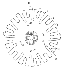
[0015] Fig. 4 is an end view of the deflector of the embodiment shown in Fig.
1.
[0016] Fig. 5 shows tables listing the results of tests that compared the
performance of the
embodiment shown in Fig. 1 with that of other commercially available
residential fire protection
sprinklers.
DESCRIPTION OF THE PREFERRED EMBODIMENT
[0017] In one aspect, our invention provides a pendent fire protection
sprinkler 10, shown in Fig.
1. Since several portions of the preferred embodiment are common to many fire
protection
sprinklers, fire protection sprinklers, these portions will not be described
in full detail, although
additional detail of these portions may be found in commonly-assigned U.S.
Patent No.
6,516,893.
[0018] The pendent fire protection sprinkler 10 of this embodiment has a body
11 having an inlet
orifice 12, an output orifice 13, and an axial passage 21 (see Fig. 2) through
the body 11, the
axial passage being provided between the inlet orifice 12 and the output
orifice 13. An exterior
of the body 11 adjacent the inlet orifice 12 is threaded to permit the pendent
fire protection
sprinkler 10 to be connected to a piping system (not shown) that delivers a
fire-extinguishing
fluid to the pendent fire protection sprinkler 10. The fire-extinguishing
fluid is often water, and
for simplicity, the fire-extinguishing fluid will generally be referred to
hereinafter as water,
although other fluids can be substituted without departing from the scope of
the invention. The
pendent fire protection sprinkler 10 is installed with the inlet orifice 12
upwards, and the
CA 2952253 2018-04-20
- 7 -
remaining portions of the pendent fire protection sprinkler 10 depending
therefrom. The pendent
fire protection sprinkler 10 may be mounted with a cover or may be exposed
(i.e., visible),
although both arrangements are well known and therefore, a detailed
description thereof is
omitted.
[0019] Two frame arms 14 extend from the body 11, and are joined together at a
hub 18 at a
distance from the body 11. The two frame arms 14 define a plane. A seal cap 15
blocks (i.e.,
seals) the output orifice 13 so as to prevent the flow of the water from the
output orifice 13, and a
thermally-responsive element 16 holds the seal cap 15 in place. The thermally-
responsive
element 16 may be, for example, a glass bulb containing a thermally-responsive
liquid that, upon
being heated sufficiently, will cause the glass bulb to break. The thermally-
responsive element
16 has one end positioned against the seal cap 15, and another end supported
by a load screw 17
that is mounted in the hub 18. The load screw 17 and the hub 18 are together
referred to as a
"hub assembly" for convenience. The thermally-response element 16, the seal
cap 15, and the
hub assembly together serve to block the output orifice 13 until occurrence of
a sufficient
temperature condition that causes the thermally-responsive element 16 to
break, as described
above. When this occurs, as is well known, the seal cap 15 is no longer held
in place in the
output orifice 13, and a pressure of the water in the piping system and the
force of gravity remove
the seal cap 15, allowing the water to flow from the output orifice 13. (This
can be visualized
most easily from Fig. 2.)
[0020] The pendent fire protection sprinkler 10 also includes a deflector 19
supported at a
bottom the frame arms 14 by the hub assembly (as shown in Fig. 2). The
deflector 19 is a disc,
as can be appreciated more easily from Fig. 4. The deflector 19 has an upper
face and a lower
CA 2952253 2018-04-20
- 8 -
face. When the pendent fire protection sprinkler 10 is actuated, the stream of
the water that
flows, under pressure, from the output orifice 13 first impinges upon an
exposed tip of the load
screw 17 and the hub 18, and then, strikes the upper face of the deflector 19.
The deflector 19 is
structured (as described below) to disperse the water so as to achieve the
required flow,
distributed properly over the area protected by the pendent fire protection
sprinkler 10. The
exposed tip of the load screw 17 and the hub 18 direct the water onto the
deflector 19, and
thereby play a key role in the proper operation of the pendent fire protection
sprinkler 10. That
is, by directing the water so that it impinges on precisely the right portion
of the deflector 19, the
exposed tip of the load screw 17 and the hub 18 help to achieve the best
possible distribution of
the water over the area to be protected. In a preferred embodiment, the
pendent fire protection
sprinkler 10 has a K factor of 7.6 gpm/(psi)1/2 or more.
[0021] To achieve a desired coverage, with the desired evenness, a number of
features and
relationships among portions of the pendent fire protection sprinkler 10 are
important, and some
features and relationships are critical. The deflector 19 must have a correct
total area, and the
water must strike the deflector 19 with a proper velocity. Also, it is
necessary for the water to
impinge on the deflector 19 a certain location. Furthermore, to achieve proper
coverage of the
area to be protected, it is not possible to use a deflector having a
conventional structure. Rather,
the deflector 19 must have a number of unconventional features, as described
below.
[0022] In the preferred embodiment, the exposed tip of the load screw 17 is
sized, shaped, and
positioned so as to create a spread in a column of the water from the output
orifice 13 onto a
disc-shaped area of a correct diameter in the middle of the deflector 19.
Controlling the size of
this disc-shaped area is very important in achieving the desired operational
characteristics at the
CA 2952253 2018-04-20
- 9 -
low pressures for which the pendent fire protection sprinkler 10 is intended
to be suitable.
Moreover, the spacing between the output orifice 13 and the deflector 19
influences the velocity
with which the water impinges on the deflector 19, and is important in
achieving an even
distribution of the water onto the walls of the area without the water being
deflected up onto the
ceiling.
[0023] Fig. 3 shows an enlarged view, partly in section, of the hub assembly.
A lower end of the
thermally-responsive element 16 is visible, resting on an upper surface of the
tip 31 of the load
screw 17. The load screw 17 is threaded into a central bore 32 in the hub 18.
The tip 31 of the
load screw 17 protrudes a certain distance (in the preferred embodiment, 0.075
inch) from an
upper surface of the hub 18, and has lateral sides 33 at a slight angle (8.5
in the preferred
embodiment) relative to a longitudinal axis of the pendent fire protection
sprinkler 10 (that axis
being the line extending from the center of the output orifice 13 to a center
of the deflector 19).
The upper surface of the tip 31 should not be excessively small (in the
preferred embodiment it is
0.108 inch). Moreover, the hub 18 itself plays an important role, and the size
of the upper
surface of the hub 18 greatly factors into reduction of dispersion of a water
column (i.e.,
reduction of the energy or velocity of the water). In the preferred
embodiment, the upper surface
of the hub 18 has a diameter of 0.285 inch. The same consideration applies to
the cross-sectional
width of the frame arms 14 at the zone of their convergence with the hub 18
(in this embodiment,
the frame arms are teardrop-shaped in cross section).
[0024] The hub 18 includes lateral sides 34 that are sloped at a slight angle
to the longitudinal
axis of the pendent fire protection sprinkler 10 (in the preferred embodiment,
the angle is 8.5 ).
It is not necessary for the entire height of each of the lateral sides 34 to
be sloped, and in the
CA 2952253 2018-04-20
- 10 -
preferred embodiment, only an upper portion measuring 0.285 inch in length of
each of the
lateral sides 34 is sloped at the angle. Finally, an upper edge of the hub 18,
where the lateral
sides 34 meet the upper surface, should not present a sharp edge to the water
flow, but should be
radiused. In the preferred embodiment, the upper edge of the hub 18 is
radiused at 0.04 inch.
[0025] Also, to achieve delivery of the proper amounts of the water to the
walls and to the floor
of the area to be protected, and with a correct distribution as between the
walls and the floor, the
deflector 19 has a number of features that are not conventional. Although it
is known to provide
a deflector with slots formed in a circumference thereof, the deflector 19 of
our invention
includes slots differing from conventional arrangements in a number of ways,
as will be
described with reference to Fig. 4. While a conventional deflector includes
slots that are formed
exactly radially, the deflector 19 of our invention has a first group of four
slots N that are not
exactly radial. These four slots N are distributed 90 apart from each other
around the
circumference of the deflector 19, with two of the four slots N being in the
plane defined by the
frame arms 14, and the other two of the four slots N lying in a plane
perpendicular to the plane
defined by the frame arms 14. The four slots N are unconventional in that they
deviate from
being exactly radial by a small amount. The four slots N are also
unconventional in that they
have slightly chamfered edges on the surface of the deflector 19 that faces
toward the floor (i.e.,
the lower face of the deflector 19).
[0026] The deflector 19 also includes a number of other slots a, b, and c that
are formed in such
a way as to define four structures resembling a bent fork (defined by slots c
and the tines
adjoining those slots), each of which is angled at about 45 relative to one
of the four slots N.
These structures are particularly important in ensuring that the water is
delivered all the way into
CA 2952253 2018-04-20
- 11 -
the corners of the area to be protected, which is especially difficult when
the fire protection
sprinkler must operate with a low water pressure.
100271 As shown in Fig. 4, each of the slots of the deflector 19 has one of
four different shapes.
In a clockwise direction from one of the four slots N, the deflector 19 has a
relatively wide,
shallow (or short) slot a, a deep and asymmetrical slot b, a slot c that is
the widest and also (by a
small margin) the shallowest of the four shapes, then another asymmetrical
slot b, and another
slot a, creating a pattern of six slots. This pattern of six slots is repeated
a total of four times
around the circumference of the deflector 19, once in each quarter of the
circumference.
[0028] Each of the asymmetrical slots b has an outer portion 41 in which a
slot width decreases
from the periphery of the deflector 19 towards the center of the deflector 19,
and an inner portion
42, in which the slot width is constant. The inner portion 42 includes both a
region 42a in which
the direction of the slot is radial, and another region 42b in which the slot
b extends in a direction
that is at an angle to a radius of the deflector 19, as shown in Fig. 4.
10029] Thus, one feature of the deflector 19 is that it has a first plurality
of slots (slots a, c, and
N), each of which has a constant width (although they are not all of the same
width), and which
extends at least approximately radially toward the center of the deflector 19
(although not
exactly, in the case of the four slots N), and a second plurality of slots,
each of which has a
portion that is non-radial (i.e., does not align with a radius of the
deflector 19), as well as a
portion having a variable width (slots b).
[00301 In addition, each of the first plurality of slots and the second
plurality of slots has a root
diameter (i.e., the width of the slot at a closed end nearest the center of
the deflector 19) that is
relatively large.
CA 2952253 2018-04-20
- 12 -
[0031] In the preferred embodiment, the deflector 19 has a diameter of 1.56
inches. The length
of each of the four slots N is 0.305 inch, and the width of each of the four
slots N is 0.065 inch.
The length of each of the slots a is 0.23 inch, and the width of each of the
slots a is 0.08 inch.
The length of each of the slots c is 0.22 inch, and the width of each of the
slots c is 0.10 inch.
Each of the asymmetrical slots b has a total depth (i.e., a distance from the
deflector periphery to
the root of the slot) of 0.3175 inch. The region 42a of each asymmetrical slot
b, nearest to the
center of the deflector 19, has a length of 0.118 inch (not including the
length of the radiused
closed end), and a width of 0.07 inch. The region 42b of each asymmetrical
slot b extends at an
angle of 12.5 relative to a radius of the deflector 19, from the region 42a
to a point that is 0.10
inch from the periphery of the deflector 19. In addition, the region 42b has a
width of 0.07 inch.
The portion 41 of each asymmetrical slot b extends an additional 0.10 inch
from the region 42b
to the periphery of the deflector 19, and has a width that increases linearly.
[0032] Also, in the preferred embodiment, the angular spacing between each of
the four slots N
to the nearest asymmetrical slot b is 32.5 , measured from a center of each of
the four slots N at
the periphery of the deflector 19 to a radius that intersects a center of the
root of the nearest
asymmetrical slot b. The angular spacing between each of the four slots N to
the nearest slot a is
15 , measured from the center of N at the deflector periphery to the radius
each of the four slots
N at the periphery of the deflector 19 to a radius that lies on the nearest
edge of the nearest slot a.
The angular spacing between each of the four slots N to the nearest slot c is
45.0 , measured
from the center of each of the four slots N at the periphery of the deflector
19 to a center of the
nearest slot c.
CA 2952253 2018-04-20
- 13 -
[0033] In addition, the deflector 19 is provided with a number of small holes
43 (in Fig. 4, the
deflector 19 has four holes 43) that permit additional delivery of the water
to the floor beneath
the pendent fire protection sprinkler 10. In the preferred embodiment, the
holes 43 are
countersunk, having a relatively larger bore on the lower face of the
deflector 19, and a relatively
smaller bore on the upper face of the deflector 19. In the preferred
embodiment, the holes 43
have a diameter of 0.045 inch on the upper face of deflector 19, and a maximum
diameter of
0.078 inch on the lower face of the deflector 19 (the bore on the lower face
of the deflector 19, is
preferably formed with so that it forms a wall at an angle of 60 relative to
the longitudinal axis
of the pendent fire protection sprinkler 10).
[0034] The placement of the holes 43 also is unconventional, in that, on a
conventional deflector,
such holes would commonly be placed in line with the plane defined by the
frame arms 14, or
along a line perpendicular to the plane defined by the frame arms 14, while
the holes 43,
according to our invention, are positioned offset from the conventional
locations (and 90 degrees
apart from each other relative to a center of the deflector 19). In the
preferred embodiment, each
of the holes 43 are 22.5 from one of the four slots N, measured from the
center of the one of the
four slots N at the periphery of the deflector 19 to a radius of the deflector
19 that passes through
a center of the hole 43. The positioning of the holes 43 also has been found
to be important in
achieving the desired operation of the pendent fire protection sprinkler 10.
[0035] These features of the deflector 19 help to ensure that the water is
distributed in the desired
way as between the floor and the walls of the area to be protected, and that
water is delivered into
the comers of the area to be protected at a sufficient rate.
CA 2952253 2018-04-20
- 14 -
[0036] The attached drawings are to scale, and the contents of those drawings
are part of the
disclosure of the present invention.
[0037] It should also be noted that, while one preferred embodiment of the
pendent fire
protection sprinkler of our invention is illustrated, it is also contemplated
to use the pendent fire
protection sprinkler in a concealed version, employing a standard cup and a
cover plate.
[0038] The tables shown in Fig. 5 provides a comparison of flows and pressures
for a
pendent/recessed fire protection sprinkler having 0.05 density and for a
pendent/recessed pendent
fire protection sprinkler having a 0.1 density, and more specifically,
provides a comparison of the
preferred embodiment of the present invention (in the columns labeled RASCO ,
a registered
trademark of The Reliable Automatic Sprinkler Co., Inc., of Elmsford, NY, USA)
with a number
of other, conventional residential fire protection sprinklers (identified in
the table by their
respective manufacturers). In each column of data, the first number is the
water flow achieved
by the fire protection sprinkler, in gallons per minute, and the second number
(in parentheses) is
the gauge pressure, in pounds per square inch, required for the fire
protection sprinkler to achieve
that flow.
100391 Based on the data shown in these tables, the pendent fire protection
sprinkler of the
present invention achieves the desired operation at relatively lower pressures
as compared with
the other sprinklers tested (i.e., the fire protection sprinklers produced by
the other
manufacturers). As is well known, this is advantageous to an end user, since
the lower pressure
demand on the fire protection system reduces the installation cost.
CA 2952253 2018-04-20