Note : Les descriptions sont présentées dans la langue officielle dans laquelle elles ont été soumises.
Application No. 2,954,809 Our
Ref: 32086-50
CA National Phase of PCT/EP2015/066476
(005892.20540)
WELDED ROOF FOR MODULAR BUILDING UNITS
CROSS REFERENCE TO RELATED APPLICATION
This application is based upon and claims benefit of copending U.S.
Provisional
Patent Application Serial No. 62/026,249 entitled "WELDED ROOF FOR MODULAR
BUILDING UNITS," filed with the U.S. Patent and Trademark Office on July 18,
2014 by
the inventor herein,
FIELD OF THE INVENTION
This invention relates generally to modular building construction, and more
particularly to a welded roof assembly for a modular building unit configured
to receive
various gutter system configurations.
BACKGROUND OF THE PRIOR ART
Roofing members for modular buildings are typically attached by way of screws
or
other fasteners, and are supplied in sheets an-anged in a tile configuration
with a portion of
one roofing sheet overlapping a portion of an adjacent roofing sheet. In order
to channel
rainwater and water from snow and ice melt away from the modular building,
gutters may be
provided along the edges of the modular building unit. However, the type of
gutter assembly,
and in fact whether a gutter system is required at all, can vary from location
to location based
upon annual weather patterns, and particularly rain, snow, and ice amounts
received in a
given area. Different weather patterns may call for different gutter
configurations, and at
times even no gutter. Moreover, even with water diversion and drainage,
conditions may
result in water collecting on the roof and leaking into the modular building
unit, such as
through gaps between adjacent roofing sheets, gaps between the roofing sheets
and the frame
of the modular building unit, openings around fasteners, and the like. While
silicone or other
fillers may be provided, they are temporary and subject to failure and leakage
over time.
1
Date recue / Date received 2021-12-06
CA 02954809 2017-01-11
WO 2016/009069
PCT/EP2015/066476
2
While differing gutter configurations may be provided to address different
rain, snow, and ice
conditions, they will require varied adaptations of the roof structure as well
in order to
accommodate the varied environmental conditions.
Thus, there remains a need in the art for a roofing configuration for a
modular
building unit that is able to accept gutters of varied configurations without
requiring
adaptation or modification of the building unit structure, and that protects
against water
leakage through the roof in all such gutter configurations, and in the case of
no gutter.
DESCRIPTION OF THE INVENTION
Disclosed is a roof assembly for a modular building unit that comprises a
roofing
sheet that is welded to the frame of the modular building unit so as to form a
unitary,
continuous sealed weld between the roofing sheet and the structural frame of
the modular
building unit, and that is pitched to downwardly direct water on the roofing
sheet toward one
end of the modular building unit. The welded roof assembly prevents water
infiltration into
the modular building unit, and such watertight structure may then receive any
gutter
configuration the user wishes to implement without risking water infiltration
into the building
unit. Further, the welded roof assembly allows the modular building unit to
carry a heavy
snow load, as the welds attaching the roofing sheet can easily carry heavy
loads. The welded
roofing sheet avoids the use of screws, and the associated possibility of
water leakage around
the screws and into the building unit. The welded roof also permits
attachment, e.g. via
welding, of safety rings or other accessories directly on the roof sheet
without need for
specialized holes or other configurations or specific location requirements.
The welded roof
also is able to employ a single slope all of the way through the full span of
the roof, thus
avoiding the need for a centrally pitched roof assembly, and its unitary
construction avoids
the tiling effect that results from the use of multiple, overlapping roofing
sheets. The welded
roof also avoids the need for silicon or other filler agents between the
unitary roofing sheet
CA 02954809 2017-01-11
WO 2016/009069 PCT/EP2015/066476
3
and the frame of the modular building unit. Still further, the recessed
roofing panel within
the exterior frame formed by the upper rails of the building unit, along with
the horizontal top
surfaces of such rails, provided for easy vertical stacking of modular
building units atop one
another.
In accordance with certain aspects of an embodiment of the invention, a roof
assembly is provided for a modular building unit, comprising: a first long
rail having a top
wall, an exterior wall, and an interior wall; a second long rail parallel to
the first long rail and
having a top wall, an exterior wall, and an interior wall; a first short rail
extending between
the first and second long rails and having a top wall, an exterior wall, and
an interior wall; a
second short rail extending between the first and second long rails and having
a top wall and
an exterior wall, wherein the first and second long rails and the first and
second short rails are
joined to form a rectangular exterior roof frame of a modular building unit;
and a roofing
sheet, wherein the roofing sheet is joined to the first short rail at a first
elevation below the
top wall of the first short rail, the roofing sheet is joined to each of the
first and second long
rails at a point below the top wall of each of the first and second long rails
and extending in a
downward slope from the first elevation, and the roofing sheet is joined to
the top surface of
the second short rail at a lowest elevation of the roofing sheet; and wherein
the roofing sheet
is joined to the first short rail, each of the first and second long rails,
and the top surface of
the second short rail by a continuous weld.
In accordance with further aspects of an embodiment of the invention, a method
of
forming a roof assembly for a modular building unit is provided, comprising
the steps of:
providing a roof frame comprising a first long rail having a top wall, an
exterior wall, and an
interior wall; a second long rail parallel to the first long rail and having a
top wall, an
exterior wall, and an interior wall; a first short rail extending between the
first and second
long rails and having a top wall, an exterior wall, and an interior wall; and
a second short rail
CA 02954809 2017-01-11
WO 2016/009069 PCT/EP2015/066476
4
extending between the first and second long rails and having a top wall and an
exterior wall,
wherein the first and second long rails and the first and second short rails
are joined to form a
rectangular exterior roof frame of a modular building unit; joining a roofing
sheet to the first
short rail at a first elevation below the top wall of the first short rail;
joining the roofing sheet
to each of the first and second long rails at a point below the top wall of
each of the first and
second long rails and extending in a downward slope from the first elevation;
and joining the
roofing sheet to the top surface of the second short rail at a lowest
elevation of the roofing
sheet; wherein the steps of joining the roofing sheet to the first short rail,
each of the first and
second long rails, and the top surface of the second short rail is performed
by making a
continuous weld.
BRIEF DESCRIPTION OF THE DRAWINGS
The numerous advantages of the present invention may be better understood by
those
skilled in the art by reference to the accompanying drawings in which:
FIG. 1 is a perspective view of a modular building unit in accordance with
certain
aspects of an embodiment of the invention.
FIG. 2 is a perspective view of a skeletal frame of the modular building unit
of FIG. 1.
FIG. 3 is a cross-sectional view of the skeletal frame of FIG. 2.
FIGS. 4a through 4d are close-up, cross-sectional views of the lower roof edge
of the
frame of FIG. 3 with varying gutter configurations.
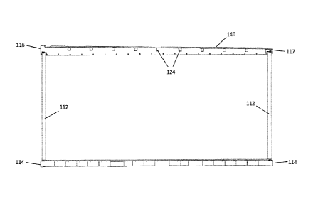
FIG. 5 is a top view of a roof portion of the modular building unit of FIG. 1.
FIG. 6 is a perspective view of the roof portion of FIG. 5.
FIG. 7 is a close-up, detail cross-sectional view of the frame of FIG. 3.
FIG. 8 is a cross-sectional view of a first, higher elevation top short rail
of the frame
of FIG. 7.
CA 02954809 2017-01-11
WO 2016/009069
PCT/EP2015/066476
FIG. 9 is a perspective view showing connection of the first top short rail
and one of
the top long rails of the frame of FIG. 7.
FIG. 10 is a cross-sectional view of a roofing sheet short side mounting
bracket of the
frame of FIG. 7.
5 FIG. 11 is a perspective view of the roofing sheet short side
mounting bracket of FIG.
10.
FIG. 12 is a close-up, detail cross-sectional view of the frame of FIG. 3
along an axis
parallel to the first top short rail (showing the long rails in cross-
section).
FIG. 13 is a perspective view of a roofing sheet long side bracket for a first
long side
of the frame of FIG. 7.
FIG. 14 is a rear view of the roofing sheet long side bracket of FIG. 15.
FIG. 15 is a cross-sectional view of the roofing sheet long side bracket of
FIG. 14
along section line A-A.
FIG. 16 is a cross-sectional view of the roofing sheet long side bracket of
FIG. 14
along section line B-B.
FIG. 17 is a cross-sectional view of a second, lower elevation top short rail
of the
frame of FIG. 7.
FIG. 18 is a perspective view showing connection of the second top short rail
and one
of the top long rails of the frame of FIG. 17.
FIG. 19 shows an external gutter and drain pipe for use with the roof portion
of FIG.
6.
FIG. 20 is a cross-sectional view of the gutter and drain pipe of FIG. 19
attached to
second top short rail of the frame of FIG. 7.
FIG. 21 shows an external water deflector for use with the roof portion of
FIG. 6.
FIG. 22 is a cross-sectional view of the water deflector of FIG. 21.
CA 02954809 2017-01-11
WO 2016/009069 PCT/EP2015/066476
6
BEST MODE(S) FOR CARRYING OUT THE INVENTION
The following description is of a particular embodiment of the invention, set
out to
enable one to practice an implementation of the invention, and is not intended
to limit the
preferred embodiment, but to serve as a particular example thereof. Those
skilled in the art
should appreciate that they may readily use the conception and specific
embodiments
disclosed as a basis for modifying or designing other methods and systems for
carrying out
the same purposes of the present invention. Those skilled in the art should
also realize that
such equivalent assemblies do not depart from the spirit and scope of the
invention in its
broadest form.
Figure 1 provides a perspective view of a modular building unit 100 in
accordance
with certain aspects of an embodiment of the invention. Modular building unit
100 includes a
skeletal frame formed by corner support posts 112, bottom rails 114, top long
rails 115, a first
top short rail 116 (shown in Figure 2), and a second top short rail 117. This
skeletal frame
provides the key structural integrity for the modular building unit.
Positioned between corner
support posts 112, bottom rails 114, and top rails 115, 116 and 117 are wall
panels 118 that
form the wall structures spanning each side of the modular building unit.
Other standard
building features, such as doors 120 and windows 122, may be provided and
integrated with
individual wall panels 118.
Figure 2 is a perspective view of the skeletal frame forming the modular
building unit
of Figure 1. As shown in Figure 2, the skeletal frame comprises four corner
posts 112
extending upward from bottom rails 114 and supporting the roof portion of the
modular
building unit 100. The roof portion includes top long rails 115 extending
lengthwise between
adjacent corner support posts 112, a first top short rail 116 extending
between adjacent corner
CA 02954809 2017-01-11
WO 2016/009069
PCT/EP2015/066476
7
supports posts 112 and generally perpendicular to top long rails 115, and a
second top short
rail 117 extending between adjacent corner support posts 112 and generally
perpendicular to
top long rails 115. A roofing sheet 140 forms the exterior roof of the modular
building unit,
and sits within the interior of the frame defined by top long rails 115, first
top short rail 116,
and second top short rail 117. Roofing sheet 140 may have a thickness of
preferably 1 to 3
mm, and more preferably 2 mm, and may either comprise a flat sheet or a
corrugated sheet
comprised of continuous or segmented ribs as shown in Figure 2. If corrugated
(which may
be desirable depending upon typical roof rain and snow loads in the locale
where the modular
building unit is to be installed), ribs from the corrugated sheet may help
with drainage of
water. The roofing sheet 140 is welded around its entire perimeter to top long
rails 115, first
top short rail 116, and second top short rail 117, all as discussed in greater
detail below, to
ensure complete water tightness, particularly in the case of snow and ice.
Roofing sheet 140
is also welded, such as by spot welding, to purlins 124 spanning the width of
the roof portion
and extending between parallel top long rails 115, again as discussed in
greater detail below.
Moreover, and as better shown in the cross-sectional view of the skeletal
frame of
Figure 3, roofing sheet 140 slopes downward from first top short rail 116 to
second top short
rail 117 so as to direct all water to the lowest elevation of the roof portion
of the modular
building unit. In order to provide such downward slope, purlins 124 are
positioned at
progressively lower elevations, with each end of each purlin being rigidly
affixed (e.g.,
welded) to an interior face of each top long rail 115. Such configuration
results in roofing
sheet 140 realizing a downward slope of preferably between 0.5% and 5% from
one end of
the module to the other. In certain configurations, roofing sheet 140 may have
two, opposite
sloping sections (not shown), each having a downward slope of 0.5% to 5% from
the middle
of the modular building unit to the end of the modular building unit.
CA 02954809 2017-01-11
WO 2016/009069 PCT/EP2015/066476
8
Because the modular building unit is configured with a fully welded roof, the
modular
building unit may be configured with varied gutter options, including no
gutter. Those
varying gutter options are shown in the exemplary configurations reflected in
Figures 4a
through 4d. Figure 4a shows the lowest roof edge of modular building unit 100,
including
roofing sheet 140 welded directly to the top face of second top short rail
117, which in turn is
mounted above wall panel 118. In this configuration, no gutter is provided, in
which case
water from the room will directly flow off of the roof, while the weld around
the perimeter of
roofing sheet 140 prevents infiltration of water into the modular building
unit. Next, Figure
4b shows the same roof edge of modular building unit 100, with a water
deflector 200
.. attached to the exterior face of second top short rail 117, which deflector
200 may aid in
directing water flowing from the roof away from the side wall panels 118 of
modular
building unit 100. Likewise, Figure 4c shows the same roof edge of modular
building unit
100, with gutter 190 attached to the exterior face of second top short rail
117, which gutter
190 may receive water flowing from the roof and direct such water to a
downspout (not
.. shown) as discussed further below. Similarly, Figure 4d shows the same roof
edge of
modular building unit 100, with an alternative gutter 119a attached to the
exterior face of
second top short rail 117, which alternative gutter 119a is attached in the
same manner as
gutter 119 but embodies a decorative design to improve the overall aesthetic
appearance of
the modular building unit 100. Those of ordinary skill in the art will
recognize that gutter
assemblies of other varying configurations may likewise be provided without
departing from
the spirit and scope of the invention.
Figure 5 provides a top view, and Figure 6 provides a perspective view, of the
roof
portion of modular building unit 100. Roofing sheets 140 are shown spanning
the full length
of the roof, and as mentioned above, may optionally include ribs 142 that may
aid in directing
water toward the lowest elevation point on the roof (i.e., toward second top
short rail 117).
CA 02954809 2017-01-11
WO 2016/009069 PCT/EP2015/066476
9
Optionally, roofing sheets 140 may be provided in separate sections, in which
each of the
sections are preferably welded together to form the same waterproof, welded
seam that is
provided along the perimeter of roofing sheet 140. Mounting brackets are
provided at the
interior faces of each of first top short rail 116 and the two top long rails
115. More
specifically, roofing sheet short side mounting bracket 144 is affixed to and
runs parallel to
first top short rail 116, and roofing sheet long side brackets 146 are affixed
to and run parallel
to each top long rail 115. Roofing sheet short side mounting bracket 144
provides a
horizontal mounting and welding surface for the highest elevation portion of
roofing sheet
140, while roofing sheet long side brackets 146 provide a downwardly angled
mounting and
welding surface for the long edges of roofing sheet 140, resulting in the
roofing sheet 140
following a downward slope from first top short rail 116 to second top short
rail 117. The
lowest elevation point of roofing sheet 140 is welded directly to the top
surface of second top
short rail 117, again allowing water on roofing sheet 140 to flow directly
onto and over
second top short rail 117.
Corner boxes 119 may be provided at each corner of the roof portion of modular
building unit 100, which corner boxes 119 principally serve as corner elements
for joining
each perpendicular pair of rails and one of corner support posts 112. Corner
boxes 119 may
also be provided features, such as openings, in the top and side walls of each
corner box 119
to receive a crane hook or other device to aid in lifting the entire modular
building unit when
necessary for transport or installation.
Figure 7 provides a close-up, detailed cross-sectional view of the skeletal
frame of
modular building unit 100. First top short rail 116 is shown at the left most
portion of Figure
7, with roofing sheet short side mounting bracket 144 extending from the
interior face of first
top short rail 116 and supporting roofing sheet 140. The underside of roofing
sheet 140
overlaps a portion of roofing sheet short side mounting bracket 144 and is
welded to short
CA 02954809 2017-01-11
WO 2016/009069 PCT/EP2015/066476
side mounting bracket 144. Likewise, as roofing sheet 140 extends toward
second top short
rail 117, it rests on and is preferably welded to purlins 124. At the opposite
end from first top
short rail 116 (i.e., the right edge as viewed in Figure 7), roofing sheet 140
overlaps a portion
of second top short rail 117 and is welded to the top of second top short rail
117.
5 Other features, including sealed joints attaching the overall roof
portion to wall panels
112, interior ceiling trays, and subfloor construction details, are shown in
Figure 7 but are not
critical to the roofing structure of the instant invention, and thus are not
described further
here.
Figure 8 is a cross-sectional view of first top short rail 116, and Figure 9
is a
10 perspective view of first top short rail 116 connecting to one of top
long rails 115 through a
connecting corner box 119. As shown in Figures 8 and 9, first top short rail
116 has a planar
top face 150, a planar outer face 152 that forms a portion of the exterior
side wall of modular
building unit 100, interior bracket flange 154, and bottom profile 156 to fit
with a modular
wall panel as shown in Figure 7. Interior bracket flange 154 extends downward
from the
interior edge of planar top face 150, and provides an attachment surface for
roofing sheet
short side mounting bracket 144.
Figure 10 provides a cross-sectional view of roofing sheet short side mounting
bracket
144, and Figure 11 provides a perspective view of such roofing sheet short
side mounting
bracket 144. Bracket 144 comprises a back wall 170 configured for attachment,
such as by
welding, to interior bracket flange 154 of first top short rail 116. Bracket
144 also has a short
side roofing sheet support surface 172 which, when bracket 144 is mounted on
first top short
rail 116, extends generally horizontally and parallel to planar top face 150
of first top short
rail 116. Support surface 172 supports the highest elevation end of roofing
sheet 140, with
the underside of roofing sheet 140 resting on the top side of support surface
172 and the two
.. being joined by a continuous weld. Bracket 144 may also include a top lip
174 extending
CA 02954809 2017-01-11
WO 2016/009069 PCT/EP2015/066476
11
generally parallel to short side roofing sheet support surface 172, which top
lip 174 limits the
opportunity for wind to blow water onto top short rail 116, so that water
remains contained
on roof sheet 140. Further, corner notches 176 are provided at opposite ends
of support
surface 172 to allow contact with edges of roofing sheet long side brackets
146, in order to
provide a continuous surface to receive a continuous weld around the entire
perimeter of
roofing sheet 140.
Next, Figure 12 provides a cross-sectional view of the skeletal frame of
modular
building unit 100 along an axis parallel to first top short rail 116 (showing
the top long rails
115 in cross section). Top long rails 115 are of generally the same cross-
sectional
configuration as first top short rail 116 (although obviously with a longer
overall length
dimension). Roofing sheet long side mounting brackets 146 are affixed (e.g.,
welded) to
interior bracket flange 154 of long rails 115 and support roofing sheet 140
along its long
edge. The underside of the long edge of roofing sheet 140 overlaps a portion
of roofing sheet
long side mounting brackets 146 and is welded to long side mounting brackets
146. Likewise
and as mentioned above, roofing sheet 140 is supported by and is preferably
welded to
purlins 124 for additional support.
Figure 13 is a perspective view of a roofing sheet long side bracket 146 for
attachment to a first one of top long rails 115. Those of ordinary skill in
the art will
appreciate that the opposite top long rail 115 will receive a similarly
configured long side
bracket 146 that is the mirror image of the bracket shown in Figure 13.
Likewise, Figure 14
is a rear view of roofing sheet long side bracket 146. Further, Figure 15
provides a cross-
sectional view of bracket 146 along section line A-A of Figure 14, and Figure
16 provides a
cross-sectional view of bracket 146 along section line B-B of Figure 14. As
shown in Figures
13 through 16, bracket 146 includes a back wall 180 providing an attachment
surface for
attaching (e.g., welding) bracket 146 to interior bracket flange 154 of top
long rails 115.
CA 02954809 2017-01-11
WO 2016/009069 PCT/EP2015/066476
12
Back wall 180 has a generally horizontal top edge and a downwardly sloping
bottom edge.
Likewise, bracket 146 has a long side roofing sheet support surface 182 which,
when each
bracket 146 is mounted on its respective top long rail 115, extends outward
from back wall
180 and provides a downwardly sloping support surface for the long edge of
roofing sheet
140, with the underside of such long edge of roofing sheet 140 resting on the
top side of
support surface 182 and the two being joined by a continuous weld. Such
continuous weld
seamlessly extends from the weld joining the highest elevation portion of
roofing sheet 140 to
short side roofing sheet support surface 172. Bracket 146 may also include a
top lip 184
extending generally parallel to top long rails 115, again serving to keep
water from being
blown off of roofing sheet 140.
Figure 17 shows a cross-sectional view of second top short rail 117, and
Figure 18 is a
perspective view of second top short rail 117 connecting to one of top long
rails 115 through
a connecting corner box 119. As shown in Figures 17 and 18, second top short
rail 117 has a
planar top face 160 configured to directly receive an overlapping portion of
the lowest
elevation section of roofing sheet 140. As noted above, roofing sheet 140 is
welded directly
to such planar top face 160 of second top short rail 117, and such weld
seamlessly continues
from the weld attaching roofing sheet 140 to each of roofing sheet short side
mounting
bracket 144 and roofing sheet long side brackets 146. Second top short rail
117 also has a
planar outer face 162 which is configured to directly receive various gutter
configurations as
discussed in greater detail below, or alternatively to form a portion of the
exterior side wall of
modular building unit 100 (in cases where no gutter system is to be used).
Second top short
rail 117 further includes planar interior face 164 and a bottom profile 166 to
fit with a
modular wall panel as shown in Figure 7.
Figure 19 shows an external gutter 190 for use with the welded roof described
above.
External gutter 190 may include a plurality of overflow openings 192 provided
on the
CA 02954809 2017-01-11
WO 2016/009069 PCT/EP2015/066476
13
outermost wall of gutter 190, and a spigot 194 at one end of gutter 190.
Spigot 194 is shaped
to fit within a drain pipe 196, which drain pipe may be joined to modular
building unit 100
with, by way of non-limiting example, an angle bracket 198, such as to one of
corner support
posts 112 that is adjacent to second top short rail 117. Likewise, Figure 20
shows a cross-
sectional view along section line C-C of Figure 19 of the gutter 190 and drain
pipe 196, with
external gutter 190 attached to second top short rail 117 with one or more
fasteners 199, such
as a screw.
Similarly, Figure 21 shows an external water deflector 200 for use with the
welded
roof described above, and Figure 22 provides a cross-sectional view of such
water deflector
200. With reference to both Figures 21 and 22, water deflector 200 has a back
wall 202 that is
configured for facing attachment to planar outer face 162 of second top short
rail 117, a
plurality of openings 204 for receiving connectors (e.g., screws) for such
attachment, and an
upper angle 206 configured to direct water outward and away from the edge of
the roof of
modular building unit 100 as it flows off of the roof.
The foregoing configuration results in a modular building unit having a roof
structure
that may readily receive a variety of gutter configurations, and that is
simultaneously
effective with no gutter, in an assembly that protects against water
infiltration into the
modular building unit regardless of the gutter configuration. Thus, a single
modular building
unit configuration may be provided in geographies having widely varied rain
and snow
conditions, with gutters being added (or not) depending upon the specific
precipitation
conditions of that particular environment, saving the user from having to
maintain multiple
configurations for differing environements.
Having now fully set forth the preferred embodiments and certain modifications
of the
concept underlying the present invention, various other embodiments as well as
certain
variations and modifications of the embodiments herein shown and described
will obviously
CA 02954809 2017-01-11
WO 2016/009069
PCT/EP2015/066476
14
occur to those skilled in the art upon becoming familiar with said underlying
concept. It
should be understood, therefore, that the invention may be practiced otherwise
than as
specifically set forth herein.