Note : Les descriptions sont présentées dans la langue officielle dans laquelle elles ont été soumises.
CA 02958658 2017-02-17
WO 2016/040235 PCT/US2015/048809
AUTOMATED RACK UNLOADING APPARATUS
TECHNICAL FIELD
The present disclosure generally relates to automation in the field of
unloading containers
stored on rack shelves.
BACKGROUND
Many different industrial operations require unloading containers from shelved
racking.
Typically, containers with goods are loaded on wheeled racks for transport to
a location in the
plant where further processing of the goods is to take place. Each rack shelf
may support a
single container or multiple containers. For example, in broiler hatchery
operations, eggs are
typically stored in multiple containers on each shelf, called multi-piece
flats, for storage and
handling. Operationally, a container must be unloaded from the rack and moved
or transported
to an operational piece of equipment, such as a conveyor for further
downstream processing in
the plant facility.
In these and other operations, the distance between shelves is typically small
and leaving
minimal clearance between the goods in each container and the shelf above. The
spacing and
configuration of the shelves on these racks is not standardized and can vary
rack-to-rack, even
within the operations at a single facility. This creates a challenge for
automation because the
rack unloading apparatus must be able to effectively remove containers from
variously
configured racks.
Known automated rack unloading systems and apparatus remove containers from
the
racks by hooking the edge of the container and pulling it off the shelf. This
approach is only
practical where a single container is stored on each shelf. In the case where
multiple containers
are stored on each shelf, each container on the shelf would have to be
individually hooked and
removed which increases the time required to unload each rack. It would be
preferable to
simultaneously remove multiple containers from each shelf in a single
operation.
Other known automated rack unloading systems for multi-piece containers or
flats insert a
"spoon" under the container(s) to thereby load the container(s) on the spoon.
The spoon and the
container(s) are withdrawn thereby unloading the rack shelf. This requires
that the leading edge of
the spoon be referenced and guided to a pre-programmed position on the shelf
which is the contact
1
CA 02958658 2017-02-17
WO 2016/040235 PCT/US2015/048809
point between the bottom of the container(s) and shelf surface so as to be
insertable thereunder.
Programming this position is unreliable given the variation in rack design,
shelf pitch and flat
designs.
Accordingly, there is a need for an automated rack unloading apparatus that is
able to meet
these objects and reliably maintain the high unloading processing rates
demanded of automated
equipment in modern operations. Furthermore, it would be desirable to provide
an associated
method.
BRIEF SUMMARY
The above and other needs are met by aspects of the present disclosure which,
according
to one aspect, provides an automated rack unloading apparatus. The apparatus
includes a frame
and a carriage assembly operably engaged with the frame. The carriage assembly
is configured
to travel vertically to align with a rack shelf on which a container to be
unloaded from the rack
shelf is located. The carriage assembly has a first end and a second end. A
spoon is pivotally
connected to the first end of the carriage assembly at a pivot point. A
retractable support
mechanism is configured to support the second end of the carriage assembly.
The retractable
support mechanism is operable to lower a leading edge of the spoon with
reference to the pivot
point to thereby downwardly incline the spoon for insertion under the
container.
Another aspect provides a method of unloading containers stored on rack
shelves. The
method comprises positioning an automated rack unloading apparatus adjacent to
a rack shelf
having a container to be unloaded therefrom. The method further comprises
vertically
positioning a carriage assembly of the automated rack unloading apparatus
proximate to the rack
shelf The method further comprises extending a spoon of the carriage assembly
such that a
leading edge of the spoon is positioned overlying the rack shelf The method
further comprises
lowering the leading edge of the spoon in an inclined position to engage the
rack shelf The
method further comprises extending the spoon to slide along the rack shelf and
underneath the
container. The method further comprises retracting the spoon to remove the
container from the
rack shelf.
Thus, various aspects of the present disclosure provide advantages, as
otherwise detailed
herein.
2
CA 02958658 2017-02-17
WO 2016/040235 PCT/US2015/048809
BRIEF DESCRIPTION OF THE DRAWINGS
Having thus described various embodiments of the present disclosure in general
terms,
reference will now be made to the accompanying drawings, which are not
necessarily drawn to
scale, and wherein:
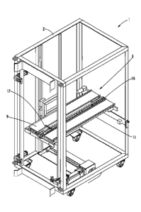
FIG. 1 is a perspective drawing of a rack unloading apparatus, according to
one aspect of
the present disclosure, with side walls removed to show the internal elements
of the apparatus;
FIG. 2 is a sectional side view of an unloading carriage assembly shown in
FIG. 1,
illustrating the details of a spoon mechanism and retractable support
mechanism; and
FIG. 3 is a sectional side view of a carriage assembly shown in FIG. 1,
illustrating the
details of a discharge conveyor mechanism.
DETAILED DESCRIPTION OF THE DISCLOSURE
Various aspects of the present disclosure now will be described more fully
hereinafter
with reference to the accompanying drawings, in which some, but not all
aspects of the
disclosure are shown. Indeed, this disclosure may be embodied in many
different forms and
should not be construed as limited to the aspects set forth herein; rather,
these aspects are
provided so that this disclosure will satisfy applicable legal requirements.
Like numbers refer to
like elements throughout.
The present disclosure discloses an automated rack unloading apparatus capable
of being
positioned or otherwise located adjacent a rack to be unloaded. The apparatus
may include a
carriage assembly, which travels vertically to align with a rack shelf on
which a container that is
to be unloaded from the rack is located. A spoon on the carriage assembly may
be pivotally
connected at one end and may be supported at the other end by a retractable
support mechanism
that is operable to lower a leading edge of the spoon with reference to a
pivot point to thereby
downwardly incline the spoon for insertion under the container.
As used in the following description, "container" refers to any tray, flat,
bin, box, or the
like used to store or transport goods, articles, materials, or other like
things. Although the
description refers to a single container on each shelf, multiple containers on
the same shelf may
be simultaneously removed by the automated rack unloading apparatus, according
to the present
disclosure.
3
CA 02958658 2017-02-17
WO 2016/040235 PCT/US2015/048809
According to one aspect of the present disclosure, an automated rack unloading
apparatus
1 is shown in FIG. 1. The apparatus 1 may have a box-like frame, or cabinet 2,
having a carriage
assembly 3 mounted on rails, which is adapted to move vertically up and down
within the
cabinet 2. Any suitable vertical positioning mechanism may be used to position
the carriage
assembly 3, such as, for example a one-axis rail-type system, mounted within
the cabinet 2 and
engaged with the carriage assembly 3 and its positioning mechanism are
controlled by any
suitable robotic control system, such as a servo drive. The cabinet 2 may be
open on all sides, as
shown in FIG. 1, or closed in which case door access is provided.
The carriage assembly 3 may have a flat elongated sheet-like device called a
spoon 9 that
is mounted within the carriage assembly 3 and adapted, in a first sequence, to
slide out of the
cabinet 2 in a forward direction for insertion underneath a container 6 and
then slide back into
the cabinet 2 in a rearward direction to thereby retrieve the container 6 from
a rack. In a second
sequence, a belt discharge mechanism may egress the container 6 from the
cabinet 2 in the
rearward direction to deposit the container 6 on an adjacent surface such as a
conveyor belt.
Between the first and second sequences described above, the carriage assembly
3 moves
vertically, as required, to reconcile the height of the shelf being unloaded
on one side of the
cabinet 2 and the adjacent conveyor surface on the other. Although a single
spoon 9 will be
referred to in the following description, two, three or more spoons 9 may be
arranged side-by-
side on the carriage assembly 3, as shown in FIG. 1. Other spoon
configurations are possible,
such as vertically spaced, with the object being to provide a good balance of
throughput and
flexibility to accommodate racks with different shelf configurations and plant
process
requirements.
The spoon 9 may have a front leading edge and a pivotal attachment at the back
edge. In
the normal or start position, the spoon is in the horizontal position. The
leading edge of the
spoon may be free to move downwardly with reference to the pivot point and is
supported
underneath by a retractable support mechanism which, in one aspect, is a cam
10. The cam 10
may be operable to rotate and lower the leading edge of the spoon 9 to orient
the spoon 9 in a
downwardly inclined position or raise the leading edge of the spoon 9 to
return the spoon 9 to the
horizontal position. Normally, the cam 10 may support the spoon 9 in the
horizontal position,
when the spoon 9 is supported on the nose 15 of the cam 10. Rotation of the
cam 10 may lower
4
CA 02958658 2017-02-17
WO 2016/040235 PCT/US2015/048809
the leading edge of the spoon 9 and inclines the spoon 9 downwardly. The cam
10 may be an
elongated or irregularly shaped disc cam.
In one aspect, the retractable support mechanism which lowers and/or raises
the leading
edge of the spoon may be a cam. Any other suitable retractable device may be
used such as a
direct air cylinder, solenoid lever arrangement or air bladder. The purpose
and function of the
retractable support mechanism is to transfer the support point for the leading
edge of the spoon 9
to the top surface of the rack shelf and use the rack shelf surface as a fixed
external reference to
reliably guide the leading edge of the spoon 9 to an optimal insertion point
between the container
and shelf surface. As a result, the spoon 9 may be inserted under the
container to load the
container.
In some instances, the spoon 9 may also be slidably mounted within the
carriage
assembly 3, preferably by engaging the pivoting end of the spoon 9 with a
pneumatic rodless
cylinder 11, attached to the carriage assembly 3. Pneumatic rodless cylinders
may have an
external carriage assembly connected to an internal piston, which both move
together along the
length of the cylinder, in response to the pneumatic pressure within the
cylinder. The spoon 9
may be pivotally attached to the rodless cylinder 11 by means of a pin, and
may slide forward
and rearward in response to actuation of the rodless cylinder 11.
As shown in FIG. 2, the spoon 9 may be pivotally mounted to the carriage
assembly 3
such as at carriage member 12 of the rodless cylinder 11 at a pivot or
attachment point 13 that is
above the height of the rotational center 14 of the cam 10. The attachment
point 13 may be
aligned with the highest point on the retractable support mechanism. When the
spoon 9 is in the
horizontal position, the nose 15, or the highest point of the cam 10 may
support the leading edge
of the spoon 9 at the point of maximum lift. Rotating the cam 10 may move the
nose 15 out of
the engagement with the underside of the spoon 9 and the spoon 9 follows the
cam 10 surface
downwardly and is thereby lowered. As a result, the spoon 9 may be level or
horizontal when
the cam 10 is fully extended and inclined downwardly when the cam 10 is
rotated out of the fully
extended position.
As shown in FIG. 3, an endless belt-type discharge conveyor 16 may be mounted
longitudinally on the carriage assembly 3, adjacent to the spoon 9. The
discharge conveyor 16
may have a flight 17, or paddle, extending therefrom and positioned to engage
with an edge of
CA 02958658 2017-02-17
WO 2016/040235 PCT/US2015/048809
the container 6 to push the container 6 in the rearward direction off the end
of the spoon 9, as
further described below.
In operation, the rack unloading process may begin with removing a container 6
from a
shelf on a rack (not shown). First, the carriage assembly 3 may be vertically
positioned, within
the cabinet 2, at each shelf so that the spoon 9 is slightly above the rack
shelf height. The spoon
9 may then be extended a distance outwardly such that the free end of the
spoon 9 is positioned
overlying the edge of the shelf The cam 10 may be then rotated to lower the
spoon 9 into the
inclined position, and may engage the leading edge of the spoon 9 with the
surface of the shelf
The lowering of the leading edge of the spoon 9 may transfer the spoon support
point from the
retractable support mechanism to the shelf surface. The rodless cylinder 11
may be then
actuated, thereby extending the spoon 9 outwardly in the forward direction to
slide along the
surface of the shelf and underneath the container 6. As the spoon 9 slides
along the shelf, the
container 6 may be lifted off of the shelf and supported by the spoon 9. The
rodless cylinder 11
may be again actuated to retract the spoon 9 in the rearward direction, within
the cabinet 2,
bringing the container 6 with it. Once the spoon 9 is refracted, the cam 10
may be rotated to
engage the nose 15 of the cam 10 with the underside of the spoon 9 and raise
the spoon to the
horizontal position, thereby transferring the spoon support from the top
surface of the shelf of the
retractable support mechanism, so that the spoon 9 and the container 6 are
level within the
cabinet 2.
The next step in the process may be to discharge the container 6 from the
apparatus 1. In
one instance, the container 6 may be egressed onto a receiving conveyor (not
shown), which is
located adjacent to the cabinet 2 on the side opposite the rack. First, the
carriage assembly 3 may
be vertically positioned adjacent to the receiving conveyor, such that the
container 6 is
positioned at or just above the top surface of the receiving conveyor. The
discharge conveyor 16
may then rotate to bring the flight 17 into contact with the forward edge of
the container 6. The
discharge conveyor 16 may continue to rotate, thereby pushing the container 6
off the spoon 9,
out of the cabinet 2 in the rearward direction, and onto the receiving
conveyor. The process may
repeat until the rack has been completely unloaded.
The tight spacing of the shelves on most racks means the apparatus 1 may be
operated
within very narrow tolerances. Supporting the free end of the spoon 9 on the
shelf may allow the
6
CA 02958658 2017-02-17
WO 2016/040235 PCT/US2015/048809
spoon 9 to slide reliably under the container 6, along the surface of the
shelf, and lift the
container 6 just high enough to remove it from the rack, without damaging the
contents of the
container 6 on the underside of the shelf above.
The spoon 9 may, optionally, be provided with an end clip, or tailgate (not
shown), at the
free end of the spoon 9, which moves between a flat position and an upright
position. When in
the flat position, the tailgate may extend from the free end of the spoon 9,
in the same plane as
the spoon 9. When in the upright position, the tailgate may extend vertically,
perpendicular to
the plane of the spoon 9. During operation, the tailgate may be kept in the
flat position until the
spoon 9 has been fully inserted into the shelf, below the container 6. The
tailgate may then be
moved into the upright position, for example by a cable mechanism, so as to
prevent the
container 6 from sliding off the spoon 9 as it is retracted into the cabinet
2.
The use of the apparatus 1, according to the present disclosure, may allow an
operator to
pre-program a rack unloading cycle for a variety of different configurations
of racks and simply
select the appropriate cycle to unload each type of rack before the apparatus
1 begins the
unloading operation. The freely pivoting capability of the spoon 9 provides
vertical compliance
that reduces damage to the contents of containers 6, during a rack unloading
operation.
Many modifications and other aspects of the present disclosure set forth
herein will come
to mind to one skilled in the art to which this disclosure pertains having the
benefit of the
teachings presented in the foregoing descriptions and the associated drawings.
Therefore, it is to
be understood that the present disclosure is not to be limited to the specific
aspects disclosed and
that modifications and other aspects are intended to be included within the
scope of the appended
claims. Although specific terms are employed herein, they are used in a
generic and descriptive
sense only and not for purposes of limitation.
7