Note : Les descriptions sont présentées dans la langue officielle dans laquelle elles ont été soumises.
CA 02961184 2017-03-13
WO 2016/043606
PCT/NZ2015/050154
A DUAL CONFIGURATION PORTABLE WHEELCHAIR
FIELD OF THE INVENTION
The present invention relates to improvements in the design of a portable
wheelchair. The portable wheelchair is collapsible for ease of deployment,
handling
and transport, while also providing a front steer configuration and a rear
steer
configuration.
BACKGROUND OF THE INVENTION
Portable and collapsible wheelchairs have been developed in the past and one
such
wheelchair is described in PCT/2013/000169.
However no dual steering
configuration wheelchairs have been described that provide a lightweight,
collapsible
and portable wheelchair with an ability to be maneuvered over moderately rough
terrain.
It is therefore an object of the invention to provide the public with a useful
choice or
to at least provide the public with a useful alternative.
SUMMARY OF THE INVENTION
The present invention provides a portable and collapsible wheelchair having an
interchangeable front wheel steer configuration and a rear wheel steer
configuration;
and having
(a) a pair of side frame assemblies each having an upper tube member and a
lower tube member and forward and aft sections; and
(b) a 6 bar linkage mounted on the side frame assemblies, which linkage
extends centrally between the side frame assemblies, which linkage is
foldable from an extended, in-use position, to a collapsed, folded,
position;
(c) a pair of front wheels with each wheel being attached to the forward
section of the side frame assemblies and wherein the front wheels can be
converted from having no swivel ability when the wheelchair is in rear
steer configuration to having swivel ability when the wheelchair is in a front
1
CA 02961184 2017-03-13
WO 2016/043606
PCT/NZ2015/050154
steer configuration,
(d) a pair of rear steer wheels that can swivel freely in a rear steer
configuration and which can be converted from having swivel ability when
the wheelchair is in rear steer configuration to having no swivel ability
when the wheelchair is in front steer configuration, with each rear wheel
being attached to the aft section of the side frame assemblies,
(e) a pair of collapsible pushing handles that are attached to the side frame
assemblies,
(f) a pair of arm rests that are attached to the side frame assemblies,
(g) a pair of back support arms that secure a back support, wherein each back
support arm is attached to the aft section of one of the side frame
assemblies and
(h) a seat support that extends above the 6 bar linkage and between the side
frame assemblies;
wherein in use the wheelchair is deployed by (i) spreading the side frame
assemblies
apart to extend the 6 bar linkage into a locked position and (ii) putting the
pair of
collapsible pushing handles into a locked in-use position and further wherein
in use
the wheelchair is collapsed by (i) pulling a handle proximate the central
position of
the 6 bar linkage to release the locked position of the 6 bar linkage to pull
the side
frames assemblies together, and (ii) collapsing the collapsible handles from
their in-
use locked position to a folded out of use position into a compact, readily
lifted and
transportable configuration; and further wherein the conversion between rear
and
front wheel steer configurations is achieved by either locking off the pivot
ability in
the rear wheels and enabling pivot ability in the front wheels to convert the
wheelchair into front wheel steer configuration or by enabling the swivel
ability in the
rear wheels and removing the pivot ability in the front wheels to convert the
wheelchair into rear wheel steer configuration..
In one embodiment the conversion of the front wheels from rear steer
configuration
to front steer configuration is achieved by replacing the front wheels with a
pair of
swivelling wheels. In one embodiment the swivelling wheels are a pair of
castor
wheels. In one embodiment the castor wheels include braking means.
In another embodiment the conversion of the rear wheels from rear steer
2
CA 02961184 2017-03-13
WO 2016/043606
PCT/NZ2015/050154
configuration to front steer configuration is achieved by locking off the
swivel ability
of the rear wheels with a locking pin. In one embodiment the locking pin is
the axle of
the front wheel used in rear steer configuration.
In one embodiment, the 6 bar linkage includes a pair of geared hinge linkages.
In another embodiment the rear wheel is biased by way of a biasing member to
keep
the rear steer wheel aligned in a substantially straight ahead manner when in
rear
steer configuration.
In another embodiment the pair of collapsible pusher handles include
ergonomically
angled handles.
In another embodiment the pair of collapsible pusher handles include a brake
lever
that activates a front wheel brake in at least one of the front wheels.
In another embodiment the wheelchair is collapsible into a size no greater
than about
800mm x about 350mm x about 700mm.
In one embodiment the wheelchair includes a pair of foot rests that are
secured to
the forward section of the side frame assembly. Preferably the foot rests can
pivot
through about 90 degrees relative to the side frame assembly.
In another embodiment each foot rest is designed to rotate upwardly against
the side
frame assembly. More preferably each foot rest is designed to rotate upwardly
against the side frame assembly and then to rotate towards the seat support.
In an
alternative embodiment each foot rest is designed to rotate towards the seat
support
and then to rotate upwardly against the side frame assembly.
In another embodiment the wheelchair further includes a lap safety belt for
use by an
occupant.
In another embodiment the wheel chair includes at least one hand brake that
acts
upon at least one of the front wheels.
3
CA 02961184 2017-03-13
WO 2016/043606
PCT/NZ2015/050154
In another embodiment the handle of the wheelchair that in use is pulled to
break the
6 bar linkage upon collapse of the wheelchair is also adapted in size and
shape to
provide a carry handle for the wheelchair in its collapsed configuration.
The foregoing brief summary broadly describes the features and technical
advantages of certain embodiments of the present invention. Further technical
advantages will be described in the detailed description of the invention that
follows.
Novel features which are believed to be characteristic of the invention will
be better
understood from the detailed description of the invention when considered in
connection with any accompanying figures and examples. However, the figures
and
examples provided herein are intended to help illustrate the invention or
assist with
developing an understanding of the invention, and are not intended to be
definitions
of the invention's scope.
BRIEF DESCRIPTION OF THE DRAWINGS
Figure 1 shows a perspective view of one embodiment of a wheelchair in rear
steer
configuration.
Figure 2 shows a perspective view of the wheelchair shown in Figure 1 without
the
seat and back rest in place in rear steer configuration.
Figure 3 shows a side view of the wheelchair shown in Figure 1 in rear steer
configuration.
Figure 4(a) shows a top view of the wheelchair in Figure 1 in a collapsed
state in rear
steer configuration.
Figure 4(b) shows a side view of the wheelchair in Figure 1 in a collapsed
state in
rear steer configuration.
Figure 4(c) shows a bottom view of the wheelchair in Figure 1 in a collapsed
state in
rear steer configuration.
4
CA 02961184 2017-03-13
WO 2016/043606
PCT/NZ2015/050154
Figure 5(a) shows a rear perspective view of the wheelchair in Figure 1 in a
collapsed state in rear steer configuration.
Figure 5(b) shows a front perspective view of the wheelchair in Figure 1 in a
collapsed state in rear steer configuration.
Figure 6(a) shows a side view of the right side frame assembly of the
wheelchair.
Figure 6(b) shows a top perspective view of the side frame assembly shown in
Figure 6(a).
Figure 6(c) shows a bottom perspective view of the side frame assembly shown
in
Figure 6(a).
Figure 7(a) shows a 6 bar linkage of the present invention as it would appear
in a
wheelchair ready for use.
Figure 7(b) shows a 6 bar linkage of the present invention as it would appear
in a
wheelchair that has been collapsed for transport.
Figure 8(a) shows the mounting of a front wheel to the forward section of the
side
frame assembly in rear steer configuration.
Figure 8(b) shows the mounting of a front wheel hand brake proximate the
forward
section of the side frame assembly in rear steer configuration.
Figure 8(c) shows the mounting of a front hub drum brake between the front
wheel
and the side frame assembly and also the components that allow for the
mounting of
the front wheel hand brake shown in Figure 8(b) in rear steer configuration.
Figure 9(a) shows a side view of the relationship between the handle, arm rest
and
the upper tube of the side frame assembly in the position when the wheelchair
is in
deployment configuration.
5
CA 02961184 2017-03-13
WO 2016/043606
PCT/NZ2015/050154
Figure 9(b) shows Detail C of Figure 9(a).
Figure 9(c) shows a side view of the relationship between the handle, arm rest
and
the upper tube of the side frame assembly when the wheelchair is in a
partially
collapsed configuration.
Figure 9(d) shows a side view of the relationship between the handle, arm rest
and
the upper tube of the side frame assembly when the wheelchair is in collapsed
configuration.
Figure 10(a) shows a side view of the rear wheel connection to the aft section
of the
side frame assembly where the rear wheel is being propelled in a straight
ahead
direction whilst in rear steer configuration.
Figure 10(b) shows a side view of the rear wheel connection to the aft section
of the
side frame assembly where the wheel is being turned in rear steer
configuration.
Figure 10(c) shows a perspective exploded view of the components of the rear
wheel
mounting connection to the side frame assembly.
Figure 10(d) shows a side view of the rear wheel showing the trail of the hub
of the
wheel relative to the centre of the pivot mount of the wheel to the side
frame.
Figure 11 shows the top and bottom perspective views of a rigid moulded
plastics
seat for use in the wheelchair of the invention.
Figures 12(a) to 12(c) show the dual rotation feature of a footrest of the
invention.
Figure 13 shows a schematic side view of the wheel chair frame of the present
invention in front steer configuration.
Figure 14(a) shows a schematic perspective view of the wheel chair frame of
the
present invention in front steer configuration.
6
CA 02961184 2017-03-13
WO 2016/043606
PCT/NZ2015/050154
Figures 14(b) and 14(c) show an exploded view of the locking mechanism for
locking
off the swivel ability of the rear wheel when converting the wheelchair to
front wheel
steer configuration.
Figures 14(d) and 14(e) show an exploded view of the connection of a front
swivel
wheel used to convert the wheel chair to front wheel steer configuration.
DETAILED DESCRIPTION OF THE INVENTION
Prior to setting forth the invention in detail, it may be helpful to provide
definitions of
certain terms to be used herein.
The term "about" as used herein in connection with a referenced numeric
indication
means the referenced numeric indication plus or minus up to 10% of that
referenced
numeric indication. For example, the language "about 50" units covers the
range of
45 units to 55 units.
With reference to Figures 1 to 3 a wheelchair 1 of one embodiment of the
invention
is shown. The wheelchair includes a pair of side frame assemblies, 2 and 3
respectively. The side frame assemblies 2 and 3 are equivalent in
configuration,
shape and dimensions except for the fact that each assembly is a mirror image
of
the other. The wheelchair 1 has a right side frame assembly 2 and a left side
frame
assembly 3 when looking at the wheelchair from the back of the chair to the
front of
the chair. The shape and configuration of the right hand side frame assembly 3
is
shown in particular detail in Figures 6(a) to 6(c). The side frame assemblies
are
constructed from metal tubing, having a round, elliptical or square cross
section.
The tubing is preferably made from aluminium or some other metal preferably
light
weight metal of about 25 mm - 32 mm (1 inch ¨ 11/4 inch) in diameter or cross
sectional width and depth. The side frame assembly includes an upper tube
member 4 and a lower tube member 5. The upper and lower tube members are
shaped by bending around formers into the desired shape. The upper tube member
4 is connected to the lower tube section in both the forward section 6 (shown
in 6(a))
and aft section 7 (shown in 6(a)). The lower and upper tube members are joined
together at their respective forward and aft sections by welds. The upper tube
7
CA 02961184 2017-03-13
WO 2016/043606
PCT/NZ2015/050154
member 4 of the side frame assembly also provides an bracket on the side frame
assembly 8 that is connected by a bolt and bracket system to the upper tube 4.
With
reference to Figures 6(a) to 6(c) the side frame assemblies include an aft
upper tube
bracket 9 that is used to connect to a back support arm 10 as shown in Figures
2
and 9(a). The aft section 7 of the side frame assembly also includes a rear
wheel
mounting bracket 11. The forward section 6 of the lower tube member 5 provides
a
mount 12 for a front wheel 13 (as shown in Figure 8) The forward section of
the
upper tube member 4 is adapted to provide means to mount a foot rest 14 (as
shown
in Figure 1) and also means for mounting a mount 15 for a front wheel hand
brake
16. The foot rest 13 in this embodiment is a standard off the shelf hinged
foot rest
constructed from a light plastic or aluminium alloy material. Preferably the
foot rest
is pivotable through about 90 degrees relative to the side frame to ease
occupant
ingress. The height of the footrests may be positioned at a plurality of
heights along
the upper side frame 4 to suit the occupant as required. As shown in the foot
rest
embodiment in Figures 12(a) to 12(c) a dual rotation foot rest mechanism is
illustrated. The foot rest 14 is first rotatable about 90 degrees towards the
side frame
as shown in Figure 12(c) about a first axle or pivot 121. The folded footrest
14 is
then further rotatable towards the seat of the wheelchair about a second pivot
point
122. The footrest when folded about the second pivot point 122 (as shown in
Figure
12(c) shows the foot rest folded against the side frame and out of the space
through
which a user must step to get into or out of the seat.
The front and rear wheels 13 and 17 respectively may optionally include
mudguards
to protect the chair occupant from splashes or dirt and dust flicking off the
wheels.
The front wheel 13 is preferably between 8-20 inches in diameter (more
preferably
around 16 inch) and includes preferably plastic or metal spokes, plastic or
metal rims
and an inflatable pneumatic tyre or polyurethane foam filled rubber tyre. The
size of
the rear wheel is a 12.5 inch wheel but it is envisaged that a range of wheel
size
from 6 inch to 14 inch would be suitable. It is also preferred that the front
and
optionally the rear wheels are removable from their axle mounts by a quick
release
axle, that is a hub push button release system or spring clip. It is also
preferred that
the front wheel includes an internal expanding shoe drum brake 18 as shown in
Figure 8(c) that is cable operated. With reference to Figure 1, the cable (not
shown)
for the brake 18 runs through or adjacent to the pushing handle 19 proximate
which
8
CA 02961184 2017-03-13
WO 2016/043606
PCT/NZ2015/050154
a brake handle 20 is provided to activate the brake. In one embodiment it is
also
envisaged that it may be desirable to have the two front brakes activated by a
single
brake lever that may activate both front wheel drum brakes 18 simultaneously.
The collapsibility of the wheelchair is achieved by a 6 bar linkage 21 as
shown in
Figures 7(a) and 7(b). The 6 bar linkage is mounted to the pair of side frames
by
way of a pair of hinge mounts 22 and 23 respectively that are positioned
between the
upper and lower tube members of the side frame assemblies 2 and 3. The hinge
mounts 22 and 23 are located substantially centrally along the length of the
upper
and lower tube members of the side frame assemblies as shown in Figures 6(a)
to
6(c). The hinge mounts span between the upper and lower tube members. With
reference to Figure 7(a) the 6 bar linkage includes a pair of geared hinge
units 24
and 25 respectively. Each geared hinge unit includes an upper hinge link
(upper
hinge links (26 and 28) respectively and lower hinge links (27 and 29))
respectively.
However, it is to be appreciated that these hinge units 24 and 25 could be
rotated 90
degrees to provide a front and rear/aft facing linkage. The hinge linkage
rotates
about a pivot point through a pair of involute sector spur gears 30 and 31
that
positively engage with each other and lead to a locked hinge arrangement when
the
wheel chair is deployed for use. The gears 30 and 31 maintain the correct
relative
positions of the links. In use, the arrangement of the hinge links is such
that you can
achieve a locking action brought about by an over centre arrangement/geometry
of
the links. Preferably the 6 bar linkage would include a positive stop on the
upper and
lower linkages that prevents the linkages from clashing around the central
pivot
section 32. In use, when the wheelchair 1 is being collapsed, the 6 bar
linkage is
broken by pulling on a handle 33 attached to the upper pair of links 26 and 28
at the
central pivot section 32. With reference to Figures 1 and 5 the handle 33 is
pulled to
extend through the seat base 34 and collapsed back rest 35 to bring the side
frame
assemblies 2 and 3 of the wheelchair 1 together. It is to be appreciated that
the
hinge links may be made out of a lightweight metal (such as aluminium,
titanium or
pressed steel) or a rigid plastic material or a composite of plastic and
metal.
The 6 bar linkage is torsionally flexible to allow the side frames to move
relative to
one another when in use. This allows all four wheels to remain in contact with
the
ground over moderate undulations and enhances the occupant's comfort and
9
CA 02961184 2017-03-13
WO 2016/043606
PCT/NZ2015/050154
wheelchair stability.
With reference to Figures 1 and 2, the pair of side frame assemblies 2 and 3
also
support a pair of arm rests 36 and 37 by way of a bracket on the side frame
assembly 8 (see Figure 6(a)-6(c) by a bolt and bracket system. A pair of
conventional arm rests 36 and 37 are provided and are shown in the embodiment
exemplified. With reference to Figure 9 (a) and Detail C as shown enlarged in
Figure
9(b) the rear of the arm rest 36 is mounted partway along the length of the
pushing
handle and the back rest upright 10. It can be seen from Figure 9(a) that
there is a
four bar linkage hinge between the collapsible pushing arms 37 and the arm
rest 36.
As shown in Figure 9(b) the bracket for the aft section of the arm rest 36
also mounts
the bracket or link at connection point 38 for the collapsible pushing arm 37.
The
arm rest link 39 at its lower end is pivotally attached to the side frame
assembly 2
along the upper tube 4 of the side frame assembly by a bracket on the side
frame
assembly 8. The bracket 8 on the upper tube 4 of the side frame assembly is a
folded plate or die cast bracket, which also connects to the arm rest linkage
44. The
connection between the pushing arm 37 and the arm rest link 39 is controlled
by a
releasable or retractable locking pin 41 that is mounted on the lower part of
the
pushing arm 37. The locking pin 41 prevents the rotation of the pushing handle
37
relative to the pushing arm link 40. The locking pin 41 slides in a sleeve 42
mounted
on the pushing arm 37. The locking pin 41 can be retracted clear of the
pushing
handle link 39 by retracting the pin into the sleeve 41 by an actuating means
43.
The pushing arm 37 at its upper end is shaped and dimensioned to provide an
ergonomically positioned handle 19. The pushing handle 19 also supports a
brake
lever 20 that controls in this example front wheel brakes and optionally other
controls
such as, rear brakes and rear wheel pivot limiters or the like.
The brake levers 20 also preferably include a locking pin (not shown) so that
the
brakes can be engaged on a permanent basis until selectively disengaged.
The above description of the wheelchair describes the features of the
wheelchair in
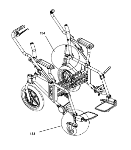
rear steer configuration. With reference to Figures 13 and 14(a)-14(e) the
following
description will describe the features of the wheelchair that allow it to be
converted
into front wheel steer configuration. Firstly, the front wheels are removed to
reveal
CA 02961184 2017-03-13
WO 2016/043606
PCT/NZ2015/050154
drum brake 18 as shown in Figure 13. The rear wheel 132 is pivoted into a
forward
position as shown in Figure 13. In other words the rear arm 130 that connects
to the
wheel 132 is rotated forwards to shorten the wheel base of the wheelchair. As
shown in blown up area 134 shown in Figure 14(a) and in Figure 14(b) a locking
pin
135, is used to lock the rear wheel in the fixed forward position by inserting
the
locking pin through sleeves 136 and 137 depicted in Figures 14(b) and Figure
14(c)
to thereby remove the swivel ability of the rear wheel. In one embodiment the
locking pin 135 is the axle of the front wheel that has been removed. A pair
of front
wheel castor wheels 131 are then inserted into the forward down tube 139 on
which
the foot rests 14 are secured as shown in Figures 13, 14(a) and 14(d) and
14(e).
The castor wheels lock into the down tube 139 located at the forward end of
the side
frame assembly 2 by way of a depressible lug. The castor wheels can be readily
engaged or removed from the chair as needed. It is important that the castor
wheels
have a built in brake 138 to allow the front wheels to be locked from rotation
for
safety reasons given that the drum brakes of the removed front wheels are not
operable.
With reference to Figure 1, the back rest uprights 10 may optionally include a
support link between the back rest uprights. The back rest 35 and seat support
34
may be made from a wear resistant fabric, such as an acrylic canvas or a nylon
canvas. Alternatively the back rest and or seat support may be a solidly
contoured
detachable insert that is put in place as required. A suitable shaped seat
support is
shown in Figure 11. The moulded plastic fibreglass or plastic seat base 45
would
clip onto the side frame and would optionally include a foam pad on the seat
pad to
provide cushioning for the occupant. The back rest may also include a moulded
plastic or fibreglass support that slides over the back rest uprights.
With reference to Figures 10(a) to 10(d) each rear wheel 17 is mounted to the
side
frame assembly by a leg 46 sliding into a rear wheel mounting bracket 11. It
is also
envisaged that a quick release mechanism provided by a depressible pin that
fits into
a complimentary hole on the leg 46 would allow for the rear wheel 17 and leg
46 to
be quickly removed for compact transport reasons. To enhance the stability of
the
rear steer wheelchair, the connection of the rear wheel 17 to the side frame
assembly 2 has been achieved by using a biasing swivel connection assembly
such
11
CA 02961184 2017-03-13
WO 2016/043606
PCT/NZ2015/050154
that when the chair is being propelled forward the wheel trails behind the leg
by a
trail distance of around 50-60 mm. This is achieved by using a biased swivel
connection 47 to (i) keep the wheel in a trailing position and discourage the
wheel
from turning and becoming unstable and (ii) to hold the wheel in a forward
facing
position when the wheel chair is collapsed and folded up into a packed
position. The
biasing may be by spring 48 and face cam 49, 50 as shown in Figures 10(a) ¨
10(c),
but it is to be appreciated that other biasing means may be employed. One such
biasing means would be the use of a detent system or a pin system that biases
the
wheel into the desirable position.
In the embodiment illustrated the angle of the side frame extending to the leg
relative
to the normal of the ground is about 4 to 8 degrees. In the embodiment shown
in
Figure 10(d) the trail 51 of the wheel is about 57 mm. This angle tends to
maintain
the wheel in the rear facing position and enhances the directional stability
of the
wheelchair.
It is to be appreciated that the overall centre of gravity of the chair, and
therefore
stability of the chair, can be modified by moving the side frames forward or
back
relative to the wheels of the chair. Similarly adjustments in the height of
the seat
relative to the wheels will also affect the overall centre of gravity of the
chair.
USE OF THE WHEELCHAIR
The wheelchair is expected to be used as any other standard wheelchair would
be
used. However, with the rear steer aspect and ease of deployment and
collapsibility
it is anticipated that this wheelchair will appeal to those wheelchair users
who like
getting out and going places. Furthermore with the use of larger front wheels
with
wider pneumatic tyres the wheelchair has the ability to go over rougher
terrain with
ease. Traditional wheelchairs will stop if their small front wheels hit a
pebble or
some other imperfection in the ground surface. It is hoped that people
associated
with wheelchair users will be more inclined to take the wheelchair to places
that
might not have been suitable for more traditional style wheelchairs.
In use, the wheelchair can be easily deployed by pulling the side frames of
the
12
CA 02961184 2017-03-13
WO 2016/043606
PCT/NZ2015/050154
wheelchair apart to lock the 6 bar linkage in a locked position. The pushing
arms of
the wheelchair can be readily pulled back into a locked position. The
footrests are
unfolded ready for the occupants feet. When the occupant is positioned in the
chair
and secured by an optional lap belt, the chair is ready for use. Once the
chair has
been used and needs to be transported say in a vehicle the pushing handles of
the
wheelchair can be folded down towards the seat of the chair, the handle that
brakes
the locked 6 bar linkage configuration is pulled and passed through the seat
of the
chair to collapse the 6 bar linkage and thereby bring the side frames of the
chair
closer together. The 6 bar linkage handle can then be used as a carry handle
to
carry the wheelchair in its collapsed configuration. Various views of the
collapsed
wheelchair are shown in Figures 4(a) to 4(c) and Figures 5(a) and (b).
The present invention and its embodiments have been described in detail.
However,
the scope of the present invention is not intended to be limited to the
particular
embodiments of the invention described in the specification. Various
modifications,
substitutions, and variations can be made to the disclosed material without
departing
from the spirit and/or essential characteristics of the present invention.
Accordingly,
one of ordinary skill in the art will readily appreciate from the disclosure
that later
modifications, substitutions, and/or variations performing substantially the
same
function or achieving substantially the same result as embodiments described
herein
may be utilized according to such related embodiments of the present
invention.
Thus, the following claims are intended to encompass within their scope
modifications, substitutions, and variations to the embodiments of the
invention
disclosed herein.
13