Sélection de la langue

Search

Sommaire du brevet 2978254 

Énoncé de désistement de responsabilité concernant l'information provenant de tiers

Une partie des informations de ce site Web a été fournie par des sources externes. Le gouvernement du Canada n'assume aucune responsabilité concernant la précision, l'actualité ou la fiabilité des informations fournies par les sources externes. Les utilisateurs qui désirent employer cette information devraient consulter directement la source des informations. Le contenu fourni par les sources externes n'est pas assujetti aux exigences sur les langues officielles, la protection des renseignements personnels et l'accessibilité.

Disponibilité de l'Abrégé et des Revendications

L'apparition de différences dans le texte et l'image des Revendications et de l'Abrégé dépend du moment auquel le document est publié. Les textes des Revendications et de l'Abrégé sont affichés :

  • lorsque la demande peut être examinée par le public;
  • lorsque le brevet est émis (délivrance).
(12) Demande de brevet: (11) CA 2978254
(54) Titre français: SUPPORT D'INSTALLATION DE STORE ENROULEUR AJUSTABLE DOTE D'UN PROTECTEUR DE TISSU DE STORE
(54) Titre anglais: ADJUSTABLE ROLLER BLIND MOUNTING BRACKET WITH BLIND FABRIC PROTECTOR
Statut: Examen demandé
Données bibliographiques
(51) Classification internationale des brevets (CIB):
  • E06B 9/42 (2006.01)
  • E06B 9/50 (2006.01)
(72) Inventeurs :
  • NG, PHILIP (Canada)
(73) Titulaires :
  • ZMC METAL COATING INC. (Canada)
(71) Demandeurs :
  • ZMC METAL COATING INC. (Canada)
(74) Agent: SMART & BIGGAR LP
(74) Co-agent:
(45) Délivré:
(22) Date de dépôt: 2017-09-06
(41) Mise à la disponibilité du public: 2018-05-24
Requête d'examen: 2022-08-04
Licence disponible: S.O.
(25) Langue des documents déposés: Anglais

Traité de coopération en matière de brevets (PCT): Non

(30) Données de priorité de la demande:
Numéro de la demande Pays / territoire Date
62/426,250 Etats-Unis d'Amérique 2016-11-24

Abrégés

Abrégé anglais


An adjustable roller blind mounting bracket comprising a bracket member
adapted for mounting to a surface, an adjustment plate slidably received upon
the interior face of the bracket member, an adjuster to alter the position of
the
adjustment plate relative to the bracket member; and a shield secured to the
adjustment plate and moveable therewith. The adjustment plate releasably
receives and supports a roller tube shaft of a roller tube of the roller
blind. The
shield has an interior side surface offset from the adjustment plate that
prevents
contact between the adjuster and blind fabric received about the roller tube.

Revendications

Note : Les revendications sont présentées dans la langue officielle dans laquelle elles ont été soumises.


CLAIMS
I CLAIM:
1. An adjustable roller blind mounting bracket comprising:
a bracket member adapted for mounting to a surface, said bracket member
having an interior face;
an adjustment plate slidably received upon said interior face of said bracket
member, said adjustment plate releasably receiving and supporting a roller
tube shaft of a roller tube of the roller blind;
an adjuster to alter the position of said adjustment plate relative to said
bracket member; and
a shield secured to said adjustment plate and moveable therewith, said
shield having an interior side surface offset from said adjustment plate and
preventing contact between said adjuster and blind fabric received about the
roller tube.
2. The mounting bracket as claimed in claim 1 wherein said bracket member
and said shield have co-operating flanges, at least one of said flanges having

a threaded bore for receiving a threaded bolt, said co-operating flanges and
said threaded bolt together comprising said adjuster.
3. The mounting bracket as claimed in claim 2 wherein said shield includes
a
bore or opening for releasably receiving the roller tube shaft of the roller
tube.
9

4, The mounting bracket as claimed in claim 3 wherein said shield includes
a
friction reducing coating on said interior side surface.
5. The mounting bracket as claimed in claim 4 wherein said co-operating
flanges comprise a first flange on said bracket member and a second flange
on said shield, said first flange including a threaded bore for receiving said

threaded bolt, said shield preventing contact between said first flange and
said threaded bolt.

Description

Note : Les descriptions sont présentées dans la langue officielle dans laquelle elles ont été soumises.

TITLE
Adjustable Roller Blind Mounting Bracket with Blind Fabric Protector
FIELD
This invention relates generally to the field of brackets used to mount roller
blinds and other similar types of window coverings.
BACKGROUND
Roller blinds, or shades as they are sometimes referred to, are common forms
of
window coverings used in residential and commercial applications. Roller
blinds
are typically mounted within or exterior to a window frame by means of
mounting brackets that are screwed or otherwise fastened to structural
elements
of the window, the window frame, a wall, or the ceiling adjacent to the window

fra me.
When mounting a roller blind or shade it is important that the blind be level
or
horizontal for not only obvious aesthetic purposes, but also to ensure a
proper
functioning of the blind. If the roller tube upon which the blind fabric is
wound is
not horizontal, the blind may tend to "telescope" on the roller tube as it is
wound
up. Excessive telescoping can cause the edge of the blind fabric to come into
contact with a mounting bracket, which can result in damage to the blind
1
CA 2978254 2017-09-06

material, or a binding of the roller tube to the point that the roller blind
will not
function properly.
It will thus be appreciated that careful and time consuming measurements are
often required in order to properly mount a blind or shade. The degree of
difficulty in mounting the brackets to hold the shade increases in situations
where the existing window, window frame, wall and/or ceiling is not perfectly
straight or perfectly plumb.
To assist in the mounting of roller blinds or shades, adjustable mounting
brackets
have been proposed. Such brackets allow for a degree of vertical movement of
the ends of the brackets in order to assist in the horizontal leveling of the
roller
tube (see for example U.S. Pat. No. 7,854,419 and 8,967,568, incorporated
herein by reference).
While such adjustable mounting brackets are of assistance in helping to
properly
orient the roller tube and to help prevent or limit telescoping of the blind
fabric,
should the blind fabric nevertheless telescope and contact the adjustment
mechanisms that are commonly present in such brackets, the edges of the blind
fabric could become damaged. The potential for damage to the blind fabric is
enhanced in cases where relatively delicate or sheer blind fabrics are
utilized.
2
CA 2978254 2017-09-06

SUMMARY
There is provided an adjustable roller blind mounting bracket comprising a
bracket member adapted for mounting to a surface, said bracket member having
an interior face; an adjustment plate slidably received upon said interior
face of
said bracket member, said adjustment plate releasably receiving and supporting
a roller tube shaft of a roller tube of the roller blind; an adjuster to alter
the
position of said adjustment plate relative to said bracket member; and a
shield
secured to said adjustment plate and moveable therewith, said shield having an

interior side surface offset from said adjustment plate and preventing contact
between said adjuster and blind fabric received about the roller tube.
BRIEF DESCRIPTION OF THE DRAWINGS
For a better understanding of the present invention, and to show more clearly
how it may be carried into effect, reference will now be made, by way of
example, to the accompanying drawings which show exemplary embodiments of
the present invention in which:
Figure 1 is a front elevation perspective view of a roller blind employing an
adjustable bracket in accordance with an embodiment of the invention.
3
CA 2978254 2017-09-06

Figure 2 is an upper side perspective view of an adjustable roller blind
mounting
bracket in accordance with an embodiment of the invention.
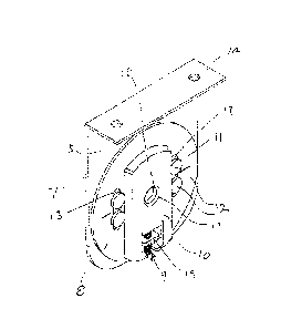
Figure 3 is a right side view of the mounting bracket shown in Figure 2.
Figure 4 is a sectional view taken along the line 4-4 in Figure 3.
Figure 5 is an exploded view of the mounting bracket shown in Figure 2.
DESCRIPTION
The present invention may be embodied in a number of different forms. The
specification and drawings that follow describe and disclose some of the
specific
forms of the invention.
Figure 1 shows a relatively standard roller blind 1 that incorporates an
adjustable
mounting bracket 2 in accordance with an embodiment of the invention. Roller
blind 1 further includes a second mounting bracket 3, with a roller tube 4
secured between the two mounting brackets. Blind fabric 5 is received about
roller tube 4. Second mounting bracket 3 would typically include a clutch
mechanism (not shown) and a chain or cord 6 for operating the roller blind.
4
CA 2978254 2017-09-06

With reference to Figures 2 through 5, in accordance with an embodiment of the

invention, mounting bracket 2 is comprised, in general, of a bracket member 7,

an adjustment plate 8, an adjuster 9, and a shield 10. Although it will be
appreciated that a variety of different forms and configurations of adjustment
plates and adjusters could be utilized, in the embodiment depicted adjustment
plate 8 is in the general form of a disc 11 that is secured to bracket member
7 by
means of a plurality of fasteners 12. One of ordinary skill will also
appreciate
that such adjustment plates are known in the art and that their position
relative
to bracket member 7 can be adjusted by a blind installer. Altering the
position of
the adjustment plate relative to bracket member 7 is typically accommodated by
the receipt of fasteners 12 through slots 13 in the adjustment plate that
permit
the adjustment plate to be slid in the direction of the longitudinal axis of
slots 13.
As shown, bracket member 7 may include a mounting flange 14 to permit the
bracket member to be mounted to a surface (for example a wall or window
frame). Bracket member 7 further includes an interior face 15 to which
adjustment plate 8 is secured. Adjuster 9 permits the slidable movement of
adjustment plate 8 along interior face 15 of bracket member 7.
In accordance with an embodiment of the invention, shield 10 is secured to (or

integrally formed with) adjustment plate 8 such that it is movable with the
adjustment plate. That is, as the adjustment plate is slidably adjusted about
interior face 15 of bracket member 7, so is shield 10. Shield 10 includes an
5
CA 2978254 2017-09-06

interior side surface 16 that is offset from adjustment plate 8 in a direction

toward roller tube 4. From a thorough understanding of the invention it will
be
understood that shield 10, and in particular interior side surface 16,
prevents
contact between adjuster 9 and blind fabric 5 received about roller tube 4.
In one embodiment of the invention, shield 10 includes a bore 17 for
releasably
receiving the roller tube shaft of roller tube 4. Bore 17 may include a
bushing or
bearing 18 to help reduce frictional contact between the shield and the roller

tube shaft. Further, the interior side surface 16 of shield 10 may include a
friction reducing coating (which may be paint, a plasticized coating, a
friction
reducing decal or outer layer, etc.) in order to further help prevent damage
to
blind fabric 5 in the event that the blind fabric should come into contact
with
interior side surface 16 .
As shown in Figures 2 through 5, bracket member 7 and shield 10 may include
co-operating flanges 19 and 20. Flange 19 comprises a first flange secured to
or
formed with bracket member 7, and flange 20 comprises a second flange formed
with or secured to shield 10. Flanges 19 and 20 are preferably generally
parallel
to one another. In the particular embodiment shown, first flange 19 includes a

threaded bore for receiving a threaded bolt 21. Flanges 19 and 20, together
with
threaded bolt 21, comprise adjuster 9. Threading bolt 21 into the threaded
bore
on first flange 19 causes the interior end 22 of bolt 21 to contact second
flange
20 such that threading the bolt into or out of first flange 19 results in a
sliding
6
CA 2978254 2017-09-06

movement of adjuster plate 8 about the interior face 15 of bracket member 7.
Second flange 20 extends inwardly from inner side face 16 of shield 10 toward
the interior face 15 of bracket member 7. Threaded bolt 21 and first flange 19

do not extend outwardly from adjuster plate 8 (toward roller tube 4) to an
extent
that they would project beyond interior side surface 16 of shield 10.
It will therefore be understood that through the incorporation of an
adjustable
mounting bracket constructed in accordance with the described embodiments of
the invention, damage to blind fabric wound about the roller tube will be
minimized or eliminated, particularly in instances where the blind fabric
telescopes about the roller tube. In some instances, despite good intentions
and
care on the part of installers, roller tubes are not mounted perfectly
horizontal.
In other instances, wear on components of the roller blind over time can cause

the roller tube to become slightly out of horizontal. If the roller tube were
non-
horizontal when blind fabric is returned to the roller tube it may have a
tendency
to "telescope" longitudinally along the length of the tube and come into close
proximity, or in some cases contact, with components of mounting bracket 2. In

situations where shield 10 is not utilized, telescoping blind fabric could
contact
portions of adjuster 9 (including threaded bolt 21) which is likely to cause
damage to the edges of the blind fabric. Through the incorporation of shield
10,
contact between blind fabric 5 and mounting bracket 2 is substantially limited
to
7
CA 2978254 2017-09-06

only interior side surface 16 of shield 10 which, as noted above, has a
tendency
to help minimize damage to the blind fabric.
It is to be understood that what has been described are the preferred
embodiments of the invention. The scope of the claims should not be limited by

the preferred embodiments set forth above, but should be given the broadest
interpretation consistent with the description as a whole.
8
CA 2978254 2017-09-06

Dessin représentatif
Une figure unique qui représente un dessin illustrant l'invention.
États administratifs

Pour une meilleure compréhension de l'état de la demande ou brevet qui figure sur cette page, la rubrique Mise en garde , et les descriptions de Brevet , États administratifs , Taxes périodiques et Historique des paiements devraient être consultées.

États administratifs

Titre Date
Date de délivrance prévu Non disponible
(22) Dépôt 2017-09-06
(41) Mise à la disponibilité du public 2018-05-24
Requête d'examen 2022-08-04

Historique d'abandonnement

Il n'y a pas d'historique d'abandonnement

Taxes périodiques

Dernier paiement au montant de 210,51 $ a été reçu le 2023-08-15


 Montants des taxes pour le maintien en état à venir

Description Date Montant
Prochain paiement si taxe applicable aux petites entités 2024-09-06 100,00 $
Prochain paiement si taxe générale 2024-09-06 277,00 $

Avis : Si le paiement en totalité n'a pas été reçu au plus tard à la date indiquée, une taxe supplémentaire peut être imposée, soit une des taxes suivantes :

  • taxe de rétablissement ;
  • taxe pour paiement en souffrance ; ou
  • taxe additionnelle pour le renversement d'une péremption réputée.

Les taxes sur les brevets sont ajustées au 1er janvier de chaque année. Les montants ci-dessus sont les montants actuels s'ils sont reçus au plus tard le 31 décembre de l'année en cours.
Veuillez vous référer à la page web des taxes sur les brevets de l'OPIC pour voir tous les montants actuels des taxes.

Historique des paiements

Type de taxes Anniversaire Échéance Montant payé Date payée
Le dépôt d'une demande de brevet 400,00 $ 2017-09-06
Taxe de maintien en état - Demande - nouvelle loi 2 2019-09-06 100,00 $ 2019-06-10
Taxe de maintien en état - Demande - nouvelle loi 3 2020-09-08 100,00 $ 2020-06-19
Taxe de maintien en état - Demande - nouvelle loi 4 2021-09-07 100,00 $ 2021-05-31
Requête d'examen 2022-09-06 814,37 $ 2022-08-04
Taxe de maintien en état - Demande - nouvelle loi 5 2022-09-06 203,59 $ 2022-08-08
Taxe de maintien en état - Demande - nouvelle loi 6 2023-09-06 210,51 $ 2023-08-15
Titulaires au dossier

Les titulaires actuels et antérieures au dossier sont affichés en ordre alphabétique.

Titulaires actuels au dossier
ZMC METAL COATING INC.
Titulaires antérieures au dossier
S.O.
Les propriétaires antérieurs qui ne figurent pas dans la liste des « Propriétaires au dossier » apparaîtront dans d'autres documents au dossier.
Documents

Pour visionner les fichiers sélectionnés, entrer le code reCAPTCHA :


Pour visualiser une image, cliquer sur un lien dans la colonne description du document. Pour télécharger l'image (les images), cliquer l'une ou plusieurs cases à cocher dans la première colonne et ensuite cliquer sur le bouton "Télécharger sélection en format PDF (archive Zip)" ou le bouton "Télécharger sélection (en un fichier PDF fusionné)".

Liste des documents de brevet publiés et non publiés sur la BDBC .

Si vous avez des difficultés à accéder au contenu, veuillez communiquer avec le Centre de services à la clientèle au 1-866-997-1936, ou envoyer un courriel au Centre de service à la clientèle de l'OPIC.


Description du
Document 
Date
(yyyy-mm-dd) 
Nombre de pages   Taille de l'image (Ko) 
Requête d'examen 2022-08-04 3 114
Changement à la méthode de correspondance 2022-08-04 2 52
Abrégé 2017-09-06 1 17
Description 2017-09-06 8 222
Revendications 2017-09-06 2 37
Dessins 2017-09-06 3 60
Dessins représentatifs 2018-04-19 1 9
Page couverture 2018-04-19 2 41
Modification 2024-01-15 13 358
Description 2024-01-15 8 312
Revendications 2024-01-15 2 49
Demande d'examen 2023-10-27 3 171