Note : Les descriptions sont présentées dans la langue officielle dans laquelle elles ont été soumises.
WELL MULTIPLE CASING INSTALLATION SYSTEM
BACKGROUND OF THE INVENTION
This application claims priority from U.S. application
Serial No.13/987,729, filed August 26, 2013.
This invention relates generally to methods and
apparatus utilized in the completion of hydrocarbon well,
and is particularly directed to methods for reducing the
amount of drillrig time and associated expense associated
with hanging casing or tubing within a previously installed
concentric outer casing.
There is need for improvements in apparatus and method
for installing casing strings in oil and gas wells, and
which reduce time and cost of such installation.
1
CA 2980906 2017-09-29
SUMMARY OF THE INVENTION
It is a major object of the invention to
provide method and apparatus to meet needs associated
with the above described operations. Basically, the
improved method of installing a plurality of casing
sections in a well, includes the steps:
a) providing hanger structure sized for
installation at a well head, the hanger structure having
a vertical through opening via which successive casing
sections are installable vertically in the well,
b) the hanger structure having vertically
spaced shoulders for landing such casing sections,
c) providing adjustable means for enabling
controllable adjustment of hanger length, whereby
ls uncemented casing weight is applied to the hanger
structure.
As will be seen, such adjustable means
typically includes wedge surfaces that induce lateral
expansion of a lower portion of the hanger structure in
response to adjustment of said means. Also, such
shoulders are defined by annularly extending supports
2
CA 2980906 2017-09-29
which are removable from said hanger structure, and
adapted to pass casing sections. The annular supports,
such as bowls, typically form progressively smaller
inner diameters, to facilitate installation and landing
of coaxial casing sections.
Another object is to provide body sections
that are laterally removably away from landed casing.
As will be seen, at least one body section includes
detachable components removable laterally away from
installed casing, at the well head. Bowl sections and
their supports are also laterally removable.
A further object is to provide for enhanced
0-ring sealing against well casing, as in installations
described herein.
The basic method of installing well head
production apparatus onto well casing successively
connected into position in a well, includes;
a) installing and landing multiple concentric
casing strings in the well, for cementing,
b) detecting unwanted weight induced
3
CA 2980906 2017-09-29
downward displacement of a selected string or strings
after attempted string cementing, and while landing
weight is temporarily relieved and until no such
downward displacement of a last installed casing string
is detected,
d) and then connecting said production
apparatus to upper extent of the last installed casing
string.
As will be seen, at least one body section is
sidewardly laterally removable away from the landed head
of casing that has been successfully cemented, to allow
connection to that head of well producing apparatus.
These and other objects and advantages of the
invention, as well as the details of an illustrative
embodiment, will be more fully understood from the
following specification and drawings, in which:
DRAWING DESCRIPTION
Fig. 1 is a vertical section taken through
assembled structure embodying the invention;
4
CA 2980906 2017-09-29
Fig. 2 is a perspective view of the Fig. 1
structure;
Figs. 3 and 4 are schematic views of completed
installation;
Fig, 5 shows a modification; and
Fig. 6 shows body section removability.
Fig. 7 shows modified 0-ring sealing.
DETAILED DESCRIPTION
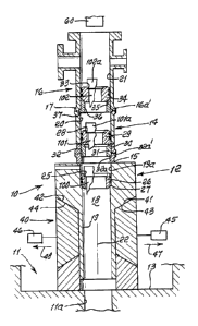
Referring first to Fig. 1, and to the Fig. 4
schematic, it shows apparatus 10 to be installed at a
well site 11 to facilitate successive installation of
casing string sections in the well. Such apparatus
includes a lower body section 12 be installed as at
surface 13, an upper body section 14 carried at 15 by
section 12, and a yet further upper body section 16
carried at 17 by section 14. All such sections may be
considered as casing hanger structure sections.
The sections define a vertical through opening
18, as at bores 19 and 19a in section 12; bore 20 in
5
CA 2980906 2017-09-29
section 14 and bore 21 in section 16, all such bores
being co-axial, i.e. with respect to common axis 22.
Through opening 18 is adapted to pass casing installable
vertically in the well ha.
The hanger structure has or includes
vertically spaced shoulders for landing different casing
sections. For example, annular shoulder 25 to support
casing 100 is defined by first annulus or bowl 26
supported at annular shoulder 27 in lower body section
12, second annular shoulder 28 to support casing 101 is
defined by second annulus or bowl 29 supported at
tapered annular shoulder 30 on annulus 31, which is in
turn supported at 32 to structure 32a associated with
body section 14; and third annular. shoulder 33 to
support casing 102 defined by third annulus or howl 34
supported at tapered annular shoulder 35 on annulus 36,
which in turn supported at 37 by the second or upper
body section 14.
Annulus 31 interf its body structure 32a and
14, and annulus 26 interf its body structure 16a and 16
aiding stabilization of the assembled body section.
6
CA 2980906 2017-09-29
In this regard, the second bowl 29 and its
support 31 are downwardly installed in the bore via
hanger body sections 16 and 14 after casing 100 is
installed downwardly; and the third bowl 34 and annular
36 are installed after casing 101 is installed
downwardly into landed position.
Adjustable means is provided for enabling
controllable adjustment of hanger length, whereby
uncemented casing weight is applied on the hanger
structure.
As shown in Fig. 1, the adjustable means 40
includes interengaged wedge surfaces 41 and 42 engaging
wedge surfaces 43 an 44 on body 12, and schematically
shown actuators 45 and 46 operable to move surfaces 41
and 42 in opposite directions 47 and 48 away from the
shoulders 43 and 44 of section 12. If section 12 then
drops, along with sections 14 and 16, it indicates that
cementing of casing 100 supported at 27 is not
completed.
A second string of casing 101 is then run into
the well, and through casing 100, and landed at 28.
7
CA 2980906 2017-09-29
Cementing is then continued through the two casings.
when cementing is completed, the wedge surfaces 41 and
42 are moved further away from surfaces 43 and 44. If
the casing drops 100, along with casing 101 and body
sections 12, 14 and 16 it means that such second
attempted cementing is not completed or effective. A
third string of casing 102 is then run into the well,
and through both casings 100 and 101. Cementing is then
continued through the three casings, until successful.
Well producing apparatus is then connected onto-the
projecting head 102a of the successively cemented casing
102 after body sections 14 and 16 are removed,
laterally, to expose casing head 102a. If casing 101
had been successfully cemented, the wall producing
apparatus could be connected to head 101a.
After the casing string or strings have been
run into position, and the last string successfully
cemented, the upper body sections 14 and 16 are:removed,
laterally away from the casing. To enable this,
sections 14 and 16 may be split to each include
detachable components 55 and 56, as shown in Fig. 6,
8
CA 2980906 2017-09-29
connected as by latches 57, or by flange connections on
the body sections, facilitating lateral removal of such
components as well as sections 58 and 59 of the bowls
and of bowl support sections respectively shown at 31
and 36. The latter may also include sections removable
laterally away from the casing, with the components 55
and 56. This enables rapid access of well production
equipment 60 to the casing head or heads seen in Fig 3,
and particularly to the casing that produces well fluid
(oil, gas, etc.) See Fig. 3 installation, -with
production connection 66 welded in position after
removal of body sections 14 and 16.
Accordingly, the method of installing well
head production apparatus onto well casing'successively
connected into position in a well, basically includes:
a) installing and landing multiple concentric
casing strings in the well, for cementing,
b) detecting unwanted weight induced downward
displacement of at least one and preferably multiple
casing strings after attempted string cementing, and
while such landing is temporarily relieved, and until no
9
CA 2980906 2017-09-29
such downward displacement of a last installed casing
string is detected
c) and then connecting said production
apparatus to upper extent of said last installed casing
string.
As will be seen, step b) typically comprises
detecting unwanted weight induced downward displacement
of multiple of the casing strings after attempted string
cementing. Such multiple strings typically include three
strings installed before cementing. -
Also, latches may be provided to hold the body
sections in position to support the bowls. The body
sections are outwardly removable to facility attachment
of well production equipment to the last installed
casing string. Body section flanges may be used instead
of latches and may be disconnected to enable section
removal. See flanges 16a and 16a', and 32a and 32a'
In the modification shown in Fig. 5, the
modified lower body section 12a has a lower extension 90
in the form of a piston, movable downwardly in cylinder
19 of uncemented casing weight is applied to bowl 26.
CA 2980906 2017-09-29
Resistance to piston downward travel, as by fluid
pressure at 92 in the cylinder, is controlled as at 93.
Fig. 7 shows a modified bowl such as bowl 34'
incorporating annular sealing structure for sealing off
against the surface of casing, such as casing surface
102a. Such structure includes an elastomeric 0-ring 92
extending about the casing and sealing at 92a against
the casing surface.
The sealing structure also includes 0-ring
annular retention surfaces 34" and 34"' formed by bowl
34' serving to pressurize and seal against the 0-ring
for enhancing its sealing at 92a against the casing
surface 102a.
A holder in the form of extension 34a' of 34'
overlies 34' and is adjustably bolted at 96 to 34'.
That extension adjustably downwardly pressurizes and
seals against the upper angular side, at 92b of the
0-ring, additionally enhancing effective and adjustable
sealing against the casing at 92a, as referred to.
Also, space 97 is created above the 0-ring to allow
pressure to deform the 0-ring, pushing it down in space
11
CA 2980906 2017-09-29
97 as well. The angular surface at 34" also acts
similarly. The pressurizing surface angles at 92b and
34" typically are between 350 and 550 in planes
containing the 0-ring axis 99.
Accordingly, an 0-ring with multiple annular
sealing surfaces is provided, corresponding to the
pressurizing annular surfaces. A second 0-ring 98 is is
spaced co-axially from 0-ring 92. See 0-ring axis 99.
As will be seen, the method of pressurizing
the 0-ring to provide enhanced sealing against the work
surface of the casing, includes the following steps, in
relation to the 0-ring axis
a) providing multiple spaced apart
pressurizing and relatively angled surfaces that extend
annularly about the 0-ring axis, and about the work,
b) and relatively displacing at least two of
said surfaces spaced apart lengthwise of said axis to
annularly engage the 0-ring at different angles, thereby
defoiming the 0-ring as it seals against the work.
The method enables provision of space adjacent
at least one of such surfaces to receive 0-ring
12
CA 2980906 2017-09-29
deformation adjacent the work. The 0-ring is
resiliently deformable, for example elastomeric.
13
CA 2980906 2017-09-29