Note : Les descriptions sont présentées dans la langue officielle dans laquelle elles ont été soumises.
JET PUMP LIFT SYSTEM FOR PRODUCING HYDROCARBON FLUIDS
BACKGROUND OF THE INVENTION
Field of the Invention
Embodiments of the present invention generally relate to artificially lifting
fluid
from a wellbore. More particularly, embodiments of the present invention
relate to
artificially lifting fluid from a wellbore using a jet pump lift system.
Description of the Related Art
To obtain hydrocarbon fluids from an earth formation, a wellbore is drilled
into
the earth to intersect an area of interest within a formation. The wellbore
may then be
"completed" by inserting casing within the wellbore and setting the casing
therein
using cement. In the alternative, the wellbore may remain uncased (an "open
hole
wellbore"), or may become only partially cased. Regardless of the form of the
wellbore, production tubing is typically run into the wellbore primarily to
convey
production fluid (e.g., hydrocarbon fluid, which may also include water) from
the area
of interest within the wellbore to the surface of the wellbore.
Often, pressure within the wellbore is insufficient to cause the production
fluid
to naturally rise through the production tubing to the surface of the
wellbore. Thus, to
carry the production fluid from the area of interest within the wellbore to
the surface of
the wellbore, artificial lift means is sometimes necessary.
Some artificially-lifted wells are equipped with sucker rod lifting systems.
Sucker rod lifting systems generally include a surface drive mechanism, a
sucker rod
string, and a downhole positive displacement pump. Fluid is brought to the
surface of
the wellbore by pumping action of the downhole pump, as dictated by the drive
mechanism attached to the rod string.
One type of sucker rod lifting system is a rotary positive displacement pump,
1
CA 2982072 2017-10-10
typically termed a progressive cavity pump ("PCP"). The progressive cavity
pump lifts
production fluid by a rotor disposed within a stator. The rotor rotates
relative to the
stator by use of a sucker rod string.
An additional type of sucker rod lifting system is a rod lift system, with
which
fluid is brought to the surface of the wellbore by reciprocating pumping
action of the
drive mechanism attached to the rod string. Reciprocating pumping action moves
a
traveling valve on the positive displacement pump, loading it on the down-
stroke of
the rod string and lifting fluid to the surface on the up-stroke of the rod
string.
Sucker rod lifting systems include several moving mechanical components.
.. Specifically, the rod strings of sucker rod lifting systems must be
reciprocated or
rotated to operate the lifting systems. In some applications, the moving parts
are
disadvantageous. When a subsurface safety valve is employed within the
wellbore,
such as within an offshore well, a sucker rod string cannot be placed through
the
subsurface safety valve. Additionally, moving parts are susceptible to failure
or
damage, potentially causing the sucker rod lifting systems to become
inoperable.
An alternative lift system involves using a jet pump. As shown in Figure 1, a
production tubing 10 having a jet pump 20 is installed in a casing 15. The jet
pump
includes a nozzle section, a venturi section, and inlets ports in fluid
communication
with the venturi section. A ported sub 22 fluidly connects the bottom of the
venturi
20 section with the annular area between the tubing 10 and the casing 15.
Production
fluid flowing up the tubing 10 can flow into the venturi section via the inlet
ports.
In operation, power fluid is directed down the tubing 10 toward the nozzle
section of the jet pump 20. Power fluid exiting the nozzle section is directed
through
the venturi section. As the power fluid passes from the nozzle section to the
venturi
section, production fluid is drawn into the venturi section via the inlet
ports. The
combined power fluid and production fluid leave the venturi section via the
ported sub
22 and enter the annular area, where the combined fluids flow upward to the
surface.
In many of these operations, a safety valve is attached to a landing nipple 23
2
CA 2982072 2017-10-10
disposed below the jet pump 20. The safety valve serves as a safety barrier
for both
the tubing 10 and the casing 15 by blocking communication through the bore of
the
tubing 10. In some instances, the jet pump is installed at depths of 8,000 ft.
or more.
Because the safety valve is below the jet pump, the safety valve must be rated
for use
at these depths. The safety valves required for these depths are usually much
more
expensive than safety valves rated for use at shallower depths; in some
instances,
more than double or triple the costs. The cost associated with control lines
for
operating the safety valves also increase with depth.
There is, therefore a need for an improved lift system for producing
hydrocarbon fluids. There is also need for a lift system that allows a safety
valve to
be installed above a jet pump.
SUMMARY OF THE INVENTION
In one embodiment, a jet pump lift system for use with a tubing disposed in a
casing includes a jet pump installed in the tubing; a one way valve for
communicating
.. a power fluid into the jet pump; and a safety valve configured to block
fluid
communication through the tubing and disposed above the jet pump.
In another embodiment, a method of producing hydrocarbon fluids includes
installing a jet pump in a production tubular; maintaining a safety valve
located above
the jet pump in an open position; supplying a power fluid through a one way
valve and
into the jet pump; urging a production fluid into the jet pump; and flowing
the production
fluid and the power fluid past the safety valve.
BRIEF DESCRIPTION OF THE DRAWINGS
So that the manner in which the above recited features of the present
invention
can be understood in detail, a more particular description of the invention,
briefly
summarized above, may be had by reference to embodiments, some of which are
illustrated in the appended drawings. It is to be noted, however, that the
appended
drawings illustrate only typical embodiments of this invention and are
therefore not to
be considered limiting of its scope, for the invention may admit to other
equally
3
CA 2982072 2017-10-10
effective embodiments.
Figure 1 shows a prior art artificial lift system using a jet pump.
Figure 2 shows an exemplary artificial lift system using a jet pump and a one
way valve.
Figure 2A is an enlarged partial view of the lift system of Figure 2.
Figure 3 illustrates an exemplary embodiment of a one way valve.
DETAILED DESCRIPTION
Embodiments of the present disclosure relate to an artificial lift system
using a
jet pump and a one-way valve for fluid communication between the jet pump and
a
power fluid source. In one aspect, the jet pump driven system advantageously
allows
a safety valve to be installed above the jet pump.
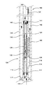
Figure 2 shows an exemplary artificial lift system for producing a hydrocarbon
fluid. Figure 2A is an enlarged partial view of Figure 2. A jet pump 120 is
installed in
a production tubing 110 disposed in a casing 115. A packer 117 blocks the
annular
area between the tubing 110 and the casing 115 below the jet pump 120.
The jet pump 120 includes a tubular housing 121 having an inlet located at a
lower end and an outlet located at an upper end. The outer surface of the two
ends
of the tubular housing 121 sealingly engages the inner surface of the bore of
the tubing
110. In this respect, production fluid flowing up the bore is directed into
the inlet of the
housing 121. In one embodiment, the ends may be sealed using one or more
sealing
members 111 such as o-rings and chevron seals.
An annular chamber 118 is defined between the two sealed ends and between
the tubing 110 and the housing 121 of the jet pump 120. A one way valve 160 is
used
to control fluid communication between the annular chamber 118 and the annular
area
113 between the tubing 110 and the casing 115. The one way valve 160 is
configured
to allow fluid in the annular area 113 to flow into the annular chamber 118.
In this
4
CA 2982072 2017-10-10
respect, the one way valve 160 prevents pressure increases, such as a blow-out
condition, from being communicated into the casing 115. An exemplary one way
valve
is a check valve. It is contemplated that a single or a plurality of one way
valves may
be used to communication fluid into the annular chamber 118. In one example,
the
one way valve 160 can be located at any location between the jet pump and the
power
fluid source. In another example, the one way valve 160 is located below the
valve
180, as shown in Figure 2. In yet another example, the one way valve 160 is
located
at a depth between 6,000 ft. and 30,000 ft., such as between 8,000 ft. and
20,000 ft.
In a further example, the one way valve is located at a depth between 6,000
ft. and
the depth of perforation.
In one embodiment, the jet pump 120 is installed in a tubing 110 having a side
pocket mandrel 114, as disclosed in U.S. Patent No. 7,228,909,
in particular, Figures 1, 2A, 2B, 3, and 5, and the
corresponding description.
Figure 3 illustrate an exemplary embodiment of a one way valve 335 suitable
for use with a side pocket of the tubing. The one way valve 335 includes a
tubular
body 305 having a generally longitudinal central bore 336 therethrough and
having an
upper end 301 and a lower end 302. The lower end 302 includes an outlet port
313
for ejecting fluid from the bore 336, and the upper end 301 includes a
connector for
connecting the one way valve to a latching mechanism for retrieval. The
tubular body
305 includes two inlet ports 331A, 331B fluidly connecting the central bore
336 to the
outside of the one way valve 335. Seal assemblies 328, 329 form a seal path
for the
fluid to enter the inlet ports 331A, 331B. A first ball and seat mechanism 340
is used
to control fluid communication between the inlet ports 331A, 331B and the bore
336.
When the fluid outside the one way valve 335 reaches a predetermined level,
the ball
will be urged away from the seat, thereby allowing fluid, such as power fluid
P, to flow
into the bore 336. A second ball and seat mechanism 350 is disposed in the
body
305 between the first ball and seat mechanism 340 and the outlet port 313. The
second ball and seat mechanism 350 allows fluid flow from the inlet ports
331A, 331B
to the outlet port 350, but does not allow fluid flow in the opposite
direction.
5
CA 2982072 2017-10-10
Date Recue/Date Received 2021-06-11
Referring back to Figures 2 and 2A, the jet pump 120 includes a nozzle section
122 spaced apart from a venturi section 124. The spaced area 125 between the
nozzle section 122 and the venturi section 124 fluidly communicates with the
bore of
housing 121. This arrangement allows fluid flowing through the inlet of the
housing
121 to flow toward the venturi section 124. A side port 126 formed in the
tubular
housing 121 provides fluid communication between the annular chamber 118 and
the
interior of the nozzle section 122. The nozzle section 122 includes a throat
128 having
an inwardly tapered portion that increases the velocity of the power fluid
flowing out
of the nozzle section 122. The venturi section 124 is configured to receive
power fluid
from the nozzle section 122 and the production fluid. The venturi section 124
includes
an outwardly tapered portion 129 that increases the pressure of the combined
fluids
flowing out of the venturi section 124 while decreasing the velocity of the
combined
fluids. Exemplary power fluids include water, oil, hydrocarbon, and
combinations
thereof.
A safety valve 180 is installed in the tubing 110 and above the jet pump 120.
In one embodiment, the safety valve 180 includes a flapper 181 movable between
an
open position and a closed position. The flapper 181 is operated by a flow
tube 182
controlled by a control line. As shown, the flapper 181 is maintained in the
open
position by the flow tube 182. To close the flapper 181, pressure is supplied
through
the control line to move the flow tube 182 upward, thereby freeing the flapper
181 to
pivot into the bore of the tubing 110 to block fluid communication through the
bore.
To open the flapper 181, pressure is supplied through the control line to move
the flow
tube 182 downward, thereby pivoting the flapper 181 away from the bore to open
fluid
communication through the bore.
In operation, production fluid 141 in the tubing 110 flows upward and enters
the
jet pump 120 via the inlet of the tubular housing 121. Power fluid 142 is
supplied down
the annular area 113 between the tubing 110 and the casing 115 toward the jet
pump
120. The power fluid 142 then passes through the one way valve 160 and enters
the
annular chamber 118. The power fluid 142 flows through the side port 126
toward the
throat 128 of the nozzle section 122. As the power fluid 142 is forced through
the
6
CA 2982072 2017-10-10
throat 128, the velocity of the power fluid 142 is increased. The power fluid
142 exiting
the throat 128 passes through the spaced area 125 and enters the venturi
section
124. As the power fluid passes from the nozzle section 122 to the venturi
section 124,
production fluid 141 in the spaced area 125 is drawn into the venturi section
124. The
combined fluids 141, 142 then flow through the outwardly tapered portion 129,
where
the velocity of the combined fluids is decreased and the pressure is
increased. The
combined fluids 141, 142 flows out of the jet pump 120 and up the tubing 110.
The
flapper 181 is retained in the open position to allow the combined fluids 141,
142 to
flow to the surface.
As discussed, embodiments of the jet pump lift system advantageously allow
the safety valve to be installed above the jet pump. Because the one way valve
prevents fluid communication from the tubing 110 into annular area 113 with
the
casing 115, the safety valve only needs to block fluid communication up the
tubing
110. In one example, the safety valve is located at 3,000 ft. or above, such
as between
200 ft. and 2,500 ft., between 1,000 ft. and 2,000 ft., and 2,000 ft. or
above. Safety
valves rated for these depths cost substantially less than safety valves rated
for much
lower depths, such as between 8,000 ft. and 20,000 ft.
Any directional terms used in the description above are merely illustrative,
for
example, the terms "upward", "downward", etc., and not limiting. It is
understood that
the production tubing described above is usable within any orientation of
wellbore,
including but not limited to a vertical, horizontal, directionally-drilled, or
lateral
wellbore.
While the foregoing is directed to embodiments of the present invention, other
and further embodiments of the invention may be devised without departing from
the
basic scope thereof, and the scope thereof is determined by the claims that
follow.
7
CA 2982072 2017-10-10