Note : Les descriptions sont présentées dans la langue officielle dans laquelle elles ont été soumises.
CA 02984452 2017-130
WO 2016/183505 PCT/US2016/032503
1
Title
Belt Drive Mechanism
Field of the Invention
The invention relates to a belt drive mechanism, and
more particularly, to a belt drive mechanism comprising a
first flexible member and a second flexible member each
having at least one segment with a tensile load of
approximately zero newtons during operation.
Background of the Invention
Wind turbines are arranged to capture energy of the
wind by means of one or more rotor blades, and to transfer
this energy into electrical energy by means of a generator.
In some wind turbines, a drive train, including a gear
arrangement, is provided for transferring rotational
movements of a hub carrying the rotor blade(s) to
rotational movements of the generator. The gear arrangement
may comprise a number of intermeshed toothed gear wheels
which provides an appropriate gearing between the
rotational movements of the hub and the rotational
movements of the generator shaft. As an alternative, the
gear arrangement may comprise a number of pulleys being
interconnected by means of a number of belts or chains, in
order to transfer rotational movements between the pulleys.
To use a belt to transmit the rotation from the rotor
to a generator is known from, among others,
W02015/058770A1. In order to prevent ratcheting or tooth
jump, a toothed belt is installed with a preload or
tension. The preload must be large enough such that the
belt will not jump on the sprocket during full load
CA 02984452 2017-130
WO 2016/183505 PCT/US2016/032503
2
operation. The preload tension is applied during
installation.
The preload tension can be a significant
source of belt wear and noise. Improper or lack of preload
may also cause tooth cracking. It can also diminish system
efficiency.
Preload for a toothed belt can be over 100
pounds depending belt pitch and width, see Wallace
Erickson, Belt Selection and Application for Engineers 277-
299, Marcel Dekker, Inc. (1987)
The prior art relies on a simple routing of the drive
belts.
Improper allocation of belt tension, routing and
alignment will reduce the operational life of a drive belt
representing significant cost to repair or replace. It
will also reduce the overall efficiency of the turbine
drive system, also representing increased costs.
Representative of the art is EP2391825 which discloses
a drive device for a windmill comprising a large pulley
disposed on a main shaft and at least one belt or chain
adapted to transfer rotation from the pulley to a
generator. The pulley is rotationally coupled to at least
two secondary shafts which are disposed parallel to the
main shaft. One or more belts which transfer the rotation,
extend over the pulley and the secondary shafts. The
secondary shafts are in turn rotationally coupled to at
least one, preferably two, electric generators.
What is needed is a belt drive mechanism comprising a
first flexible member and a second flexible member each
having at least one segment with a tensile load of
approximately zero newtons during operation.
The present
invention meets this need.
CA 02984452 2017-10-30
WO 2016/183505 PCT/US2016/032503
3
Summary of the Invention
An aspect of the invention is to provide a belt drive
mechanism comprising a first flexible member and a second
flexible member each having at least one segment with a
tensile load of approximately zero newtons during
operation.
Other aspects of the invention will be pointed out or
made obvious by the following description of the invention
and the accompanying drawings.
The invention comprises a belt drive mechanism
comprising a first disc in rotational relation to a
secondary shaft, a first flexible member engaged between
the first disc and the secondary shaft to rotationally
drive the secondary shaft about its axis of rotation, the
first flexible member having a segment with a tensile load
of approximately zero newtons during operation, a second
flexible member engaged between the secondary shaft and an
output shaft to rotationally drive the output shaft, the
second flexible member having a segment with a tensile load
of approximately zero newtons during operation, and the
output shaft connectable to a load.
Brief Description of the Drawings
The accompanying drawings, which are incorporated in
and form a part of the specification, illustrate preferred
embodiments of the present invention, and together with a
description, serve to explain the principles of the
invention.
Figure 1 is a perspective view of the transmission.
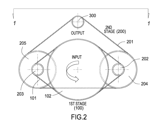
Figure 2 is a schematic of the drive arrangement.
Figure 3 is a plan view schematic of the drive
arrangement.
CA 02984452 2017-10-30
WO 2016/183505 PCT/US2016/032503
4
Figure 4 is a schematic of the first stage drive.
Figure 5 is a schematic of the second stage drive.
Figure 6 is a rear perspective view of an alternate
embodiment.
Figure 7 is a front perspective view of an alternate
embodiment.
Figure 8(a) is a plan view of a toothed belt.
Figure 8(b) is a plan view of a ribbed belt.
Figure 9 is a front perspective view of the drive
schematic as shown in Figure 2.
Detailed Description of the Preferred Embodiment
Figure 1 is a perspective view of the transmission.
The transmission is disposed in a typical nacelle frame
400. The transmission comprises first shaft 102 journalled
to the frame in pillow blocks 401. Second disc 204 and 205
are each connected to their respective shafts (202 and 203)
which are in turn journalled to the frame on pillow blocks
401.
Flexible drive member 101 is trained between the
first shaft disc and each of the secondary shafts. Rotor
shaft 102a is connected to a rotor (not shown), such as a
wind turbine prop.
Shaft 102(a) is the shaft for power
input to the transmission.
Generator 302 is mounted to the frame 400.
Flexible
drive member 201 is trained between each secondary shaft
disc 204, 205 and the generator sprocket 300. Sprocket 300
is mounted to shaft 301. Generator 302 is the load for the
system.
An inventive feature of the system is that a slack
side tension for the 1st stage flexible drive member 101 and
the 2'd stage flexible drive member 201 are each low, but
greater than zero newtons upon installation. Both
CA 02984452 2017-10-30
WO 2016/183505 PCT/US2016/032503
installation tensions then decrease, tending to zero
newtons as full load torque is applied to each stage of the
drive. The transmission is a step-up transmission. Most
wind turbines rotate from 5 to 20 RPM depending on wind
5 speed.
The step up ratio of the instant transmission is
about 80 to 1.
Figure 2 is a schematic of the drive arrangement. The
first stage drive 100 comprises a flexible drive member 101
that is trained about a first disc 102. A
radius R1
establishes an outer perimeter of first disc 102. First
disc 102 is attached to a rotor (not shown) such as on a
wind turbine. Rotation of the first disc is caused by wind
impinging on the rotor blades.
Flexible drive member 101 may comprise a toothed belt,
multiple-ribbed belt, flat belt or a chain. The
outer
perimeter of first disc 102 is toothed, ribbed or flat to
engage flexible drive member 101.
Flexible drive member
101 may comprise one or more members (a,b,c) mounted side
by side in parallel.
Flexible drive member 101 engages shaft 202 and shaft
203.
The portion of shaft 202 and shaft 203 that engages
flexible drive member 101 is configured as toothed, ribbed
or flat to engage member 101.
Each shaft 202 and 203 is
journalled in pillow blocks 401 or other suitable bearings
to allow rotation. The pillow blocks or other bearings are
mounted to a frame 400. Frame 400 is mounted in a turbine
nacelle (not shown).
Disc 204 is fixed to shaft 202. Disc 205 is fixed to
shaft 203.
Flexible drive member 201 is trained between disc 204,
disc 205 and output shaft 300.
Flexible drive member 201
may comprise one or more members (a,b,c) in parallel.
CA 02984452 2017-10-30
WO 2016/183505 PCT/US2016/032503
6
Flexible drive member 201 may comprise a toothed belt,
multiple-ribbed belt, flat belt or chain.
The portion of sprocket 300 that engages flexible
drive member 201 is configured as toothed to engage member
201.
Shaft 301 can be connected to a driven load such as
an electrical generator 302. The axis of rotation of shaft
301 can be disposed radially outward of the outer perimeter
R1 of first disc 102.
Figure 3 is a plan view schematic of the drive
arrangement. The
first stage 100 is coupled to a rotor
(not shown). The second stage 200 is disposed between the
first stage 100 and an output shaft 301 load, such as an
electric generator 302.
Figure 4 is a schematic of the first stage drive.
System variables for the first stage are identified in
Figure 4. A slack side member segment is indicated by T30.
Since the input torque is split between shaft 202 and shaft
203, there are two belt segments having a slack
characteristic at full load, namely, segment 101a and
segment 101b. "Slack" refers to having little or no tensile
load. In
this case the driver is disc 102 and the driven
is shaft 202 and shaft 203. Direction of rotation is shown
by the arrows in the figures. In an alternate embodiment an
electric generator or other load may be directly connected
to each shaft 202, 203.
Figure 5 is a schematic of the second stage drive.
System variables for the second stage are identified in
Figure 5.
The slack side member segment is indicated by
T30. Segment 201a has a slack characteristic.
For this
second stage there are two drivers, 204 and 205. The
driven is shaft 301. Direction of rotation is shown by the
CA 02984452 2017-10-30
WO 2016/183505
PCT/US2016/032503
7
arrows.
Both first stage and second stage rotate in the
same direction. The direction of rotation may either be
clockwise or counter-clockwise. In
this example it is
counter-clockwise when viewed from the rotor end (input
end) as shown in Figure 4 and Figure 5.
An example solution for the inventive drive follows.
..õ \.:==1 , , =1=1`
k = ...\\\\
*******
Generator power [KW] 500 500
Generator speed [RPM] 1521 1521
Q EN -m] 3139 3139
Pitch [mm] 19 19
====================
========================.......................................................
.........................................
,
Modulus [N/mm] 175911 175911
[mm] 500 500
w ynmj Jou AtOggUnununmum
[mm] 1100 1114
L [mm] 1100 960
[mm] 3000 1500
2t
L m1 3000 2910
2m
[N] 28836 28836
T [N] 13463 14435
[N] 87012 81510
T [N] 76200 81702
[N-m] 13156 12324
Q IN -m] 11521 12353
CA 02984452 2017-10-30
WO 2016/183505
PCT/US2016/032503
8
43156ii 12324iii
======:::fr
iiiiiiirtHUMMTMMMK
...............................................................................
......................................................................
...................................................
iiii9.4111111111111111111111111111111111111111111111111111111111111111111111111
1111111111111111111111111111111100111111111111111111111111111111111111111111111
1111111111111111111111144711111143761111111111111111111111111111111111111111111
111111111111iiiiiiiiiiiiii
R2 1mm] 860
iiiiiiii01111111111111111111111111111111111111111111111111111111111111111111111
111111111111111111111111111otirg11I113tiflrii] 12 120
=111111111111111111111111111111111111111111111iiiiiiiiiiii
iiiiiiiiiiimongmgmgmgmggiNgungoongo
Each of the variables is defined as follows:
Symbol [unit] description
01 [rad] rotation of the shaft 203
0, [rad] rotation of the shaft 202
Oi [rad] rotation of the disc 102
R1 [mm] radius of the disc 102
r1 [mm] radius of the shaft 203 and shaft 202
Ti [N] tight side tension of drive member 101
Tr [N] tight side tension of drive member 101
Is [N] slack side tension of drive member 101
L11 [mm] 1st stage drive span length
Lir[mm] 1st stage drive span length
M1 [N/mm] belt modulus belt 101
[mm] 1st stage drive 101 width
Qi [N-mm] torque transmitted by shaft 203
Q, [N-mm] torque transmitted by shaft 202
Qo [N-mm] output torque of shaft 300
Os [rad] rotation of the shaft 301
R2 [mm] radius of sprocket 205
r2 [mm] radius of sprocket 300
r3 [mm] radius of secondary shaft 202, 203
CA 02984452 2017-10-30
WO 2016/183505 PCT/US2016/032503
9
Ti [N] tight side tension of drive member 201
12 [N] middle span tension of drive member 201
13 [N] slack side tension of drive member 201
L2t[mm] 2nd stage drive, tight span length of drive
member 201
L2m[mm] 2nd stage drive, middle span length of drive
member 201
L23 [ITIM1 2nd stage drive, slack span length of drive
member 201
m2 [N/mm] belt modulus of belt 201
w2 [min] 2nd stage drive belt 201 width
Qt [N-mm] torque transmitted between the tight span Ti
and middle span 12
Qm [N-mm] torque transmitted between the middle span 12
and slack span 13.
"Symmetric" refers to a system wherein member segments
201a and Ti on each side of the output shaft 301 are of
equal length.
"Asymmetric" refers to a system wherein
segments 201a and Ti are not of equal length.
For a flexible member drive with no member tensioners,
also called a "lock center drive", the initial installation
tension for flexible drive member 101 and flexible drive
member 201, namely, Ts and 13, can be determined in the
following manner:
1. A flexible member, in this case a toothed belt for
example, is placed between two toothed sprockets of
equal size on a test machine. The belt is then
subjected to a static pull (load). Before the load is
applied the belt is in a somewhat slack shape. In this
state the sprocket hub load versus travel curve is
very flat since there is no load on the belt. This is
the seating region. Once the belt is seated, the two
CA 02984452 2017-10-30
WO 2016/183505 PCT/US2016/032503
belt segments between the sprockets become straight as
each takes up load. At this point sprocket load
versus travel will enter a linear region showing
sprocket movement (x) versus load (y). The transition
5 knee
from a horizontal line (no load: y=0) to linear
(loaded) can be easily identified. The tension at the
knee region is the required initial tension TO
necessary to keep the belt span segments straight.
This value is the minimum value of the initial
10
installation tension for the subject belt: TOm,õ. This
method can be applied to member 101 and 201.
2. The maximum torque for the operational system is Qmax=
Using DTR = 8, one can determine the initial
installation tension TO1 for the given belt.
First,
the test system is run at TO1 with ()max. There should
be no belt tooth jump during this test. Tooth jump
occurs when a tooth disengages from the sprocket to
skip or "jump" to the next adjacent tooth.
This
typically occurs in low belt tension situations.
3. The initial value of TO1 is then reduced by half,
T02=(T01)/2, and the test is re-run. If
there is no
tooth jump detected, the second value is reduced by
half again, T03=(T02)/2.
4. This process is repeated until tooth jump is detected.
Once tooth jump is detected the proper installation
tension is reset to the previous level TO1, that is,
the last setting where no tooth jump was detected.
The test is rerun at T0,1 to confirm this tension
setting. At full load the final tension setting for
the slack side (Ts or T3) should be approximately zero
newtons.
CA 02984452 2017-10-30
WO 2016/183505 PCT/US2016/032503
11
For the lock center drive, the proper initial tension for
the installed flexible drive member segments, Ts and 13, can
then be achieved by:
1. Move each shaft 202 and shaft 203 radially outward,
away from the axis of rotation "A" of disc 102, to set
the 1st stage drive initial tension T. This is
preferably the position where all segments are
straight.
2. Install the 2'd stage sprockets 204, 205, but do not
lock them down to either shaft 202, 203. A taper lock
bushing is a means to achieve this. For this step
each disc 204, 205 is left free to rotate about each
shaft 202, 203. Any suitable lubricant can be used to
temporarily lubricate the shafts.
3. Move the generator shaft 300 radially outward from
axis A against the second stage flexible drive member
201 to set an initial tension 13. This is preferably
the position where all segments are straight.
4. Lock each of the sprockets 204, 205 onto its
respective shaft 202, 203.
5. Start up the system and check for tooth jump for both
drive members at full load. If
jump occurs, move
shaft 202, 203 or shaft 300 of the respective drive
member to slightly increase the belt tension. Repeat
check and adjust as needed until no tooth jump occurs
at full load.
Figure 6 is a rear perspective view of an alternate
embodiment. In
this embodiment the second stage drive
comprises three toothed discs 204, 205, 206. In
this
embodiment power (torque) from the rotor 102 is split into
thirds, each third transmitted to one of three secondary
shafts. Each secondary shaft 207, 208, 209 is engaged with
CA 02984452 2017-10-30
WO 2016/183505 PCT/US2016/032503
12
the flexible member 101.
Each toothed disc 204, 205, 206
is connected to a respective secondary shaft 207, 208, 209.
Each of the secondary shaft discs is engaged with flexible
member 201. Each secondary shaft can be toothed to engage
a toothed belt flexible member 201. Each
secondary shaft
can also be ribbed or flat.
Flexible member 101 engages an outer perimeter of
first disc 102. In
order to enhance power transfer from
first disc 102 to flexible member 101, idlers 204a, 205a
and 206a are used to press flexible member 101 into
engagement with the outer perimeter of first disc 102. The
additional circumference of engagement causes more teeth of
flexible member 101 to engage first disc 102, which in turn
decreases the loading per tooth. This in turn reduces the
chance of tooth skip at elevated power conditions (high
torque), where power (HP) = (torque x speed)/5252.
Each idler 204a, 205a and 206a serves to route
flexible member 101 so as to increase the number of teeth
engaged with each shaft 207, 208, 209.
The routing wraps
more of flexible member 101 about each shaft, also referred
to as wrap angle (a), which then reduces the chance of
tooth skip under elevated power conditions. The wrap angle
(a) about each shaft 207, 208, 209 is greater than 120
degrees.
Flexible member 201 engages each disc 204, 205, 206.
Flexible member 201 also engages idler disc 210 and toothed
disc or sprocket 300. Sprocket 300 is connected to a load
such as a generator 302. Disc 210 is used to increase the
wrap angle (0) of the flexible member 201 about sprocket 300
to greater than 120 degrees and up to approximately 180
degrees.
CA 02984452 2017-10-30
WO 2016/183505 PCT/US2016/032503
13
Figure 7 is a front perspective view of an alternate
embodiment. Each idler 204a, 205a and 206a routes flexible
member 101 to establish a suitable wrap angle a about each
shaft 207, 208, 209. As such each idler helps to determine
belt routing, but is not used to apply a significant
preload to the belt, therefore the condition T0 is
maintained at full load.
Idler disc 210 routes flexible member 201 to establish
a suitable wrap angle 0. As such idler disc 210 helps to
determine belt routing but is not used to apply a
significant preload to the belt, therefore the condition
T30 is maintained at full load.
Figure 8(a) is a plan view of a toothed belt. A
toothed belt comprises teeth 800 which extend across a
width (w) of the belt.
Figure 8(b) is a plan view of a ribbed belt. A ribbed
belt comprises ribs 801 which extend in the longitudinal
(endless) direction of the belt. A flat belt comprises no
teeth or ribs.
Figure 9 is a front perspective view of the drive
schematic in Figure 2.
Shaft 102a can be connected to a
propeller shaft (not shown). Shaft 301 can be connected to
a load such as a generator.
Although a form of the invention has been described
herein, it will be obvious to those skilled in the art that
variations may be made in the construction and relation of
parts without departing from the spirit and scope of the
invention described herein.