Note : Les descriptions sont présentées dans la langue officielle dans laquelle elles ont été soumises.
CA 02985990 2017-11-14
[DESCRIPTION]
[Invention Title]
VEHICLE EMERGENCY SAFETY DEVICE USING SELFIE STICK
[Technical Field]
The present invention relates to a vehicle emergency
safety device using a selfie stick, which is attachable to
a vehicle door when a vehicle unavoidably stops due to an
accident of the vehicle or another vehicle ahead on a road,
and gives an easily recognizable warning to following
vehicles to prevent secondary or tertiary accidents.
[Background Art]
Among traffic accidents occurring on motorways, a
rate of secondary accidents due to driver inattention,
e.g., rear-end collisions caused because an accident is
not recognized in advance and crashes into a stationary
vehicle on the shoulder of a road, gradually increases and
thus loss of life and property also increases.
To inform following vehicles of a hazardous
situation ahead on a road or an emergency stop of a
vehicle, every vehicle has emergency lights which flicker
when manipulated by a driver. In
particular, when the
vehicle stops on a road or on the shoulder of the road to
check an error or breakdown caused while driving, the
1
CA 02985990 2017-11-14
emergency lights should be turned on and a warning
triangle should be placed 100 to 200 m behind the stopped
vehicle. Every driver is obliged by the Road Traffic Act
to carry and use a warning triangle. The warning triangle
is produced to be easily recognizable not only in the
daytime but also in the nighttime by reflecting light
emitted from headlights. Currently, the warning triangle
includes a light-emitting diode, an illuminator, or the
like which emits light to increase recognizability and
visibility.
A selfie stick includes a cradle for holding a
smartphone, and an extendable stick connected to the
bottom of the cradle, and retracted when carried and
extended when used.
For example, Korean Utility Model Registration No.
20-352673 discloses a detachable signal tube holder for
holding an expendable and reusable signal tube containing
compressed gunpowder and capable of maintaining a total
intensity of light even when the number of emergency lamps
or signal tubes thrown onto the ground is reduced, to warn
long-distance drivers of a traffic accident, the signal
tube holder including a cylindrical body having, at an end
thereof, a connection hole to which the signal tube is
connected and fixed, a plurality of rotation members
hinge-rotatably supported by the end of the cylindrical
2
CA 02985990 2017-11-14
body and spread in a radial shape, a movable ring spaced
apart from a hinge point of the rotation members by a
predetermined distance and slidable on the body, a draft
spring for generating traction power to move the movable
ring with respect to the rotation member supporting end of
the body, and a support member hinge-rotatably supported
between the movable ring and the rotation members to
rotate the rotation members in association with movement
of the movable ring.
Korean Utility Model Registration No. 20-40946
discloses a vehicle safety lamp which is turned on by
combining a plurality of retractable poles 2, 2', and 2"
having different diameters, onto the top of a body 1,
mounting a lamp 3 on the top pole 2", coiling a wire 6 on
a coiled part 5 produced by coiling a ferroelastic spring
5' around a short shaft 4 in the body 1, to be inserted
into the plurality of poles 2, 2', and 2" and wired to the
lamp 3, and connecting a power input wire 7 to the wire 6
coiled on the coiled part 6 using a terminal.
Korean Patent Registration No. 10-352673 discloses a
detachable signal tube holder for holding an expendable
and reusable signal tube containing compressed gunpowder
and capable of maintaining a total intensity of light even
when the number of emergency lamps or signal tubes thrown
onto the ground is reduced, to warn long-distance drivers
3
CA 02985990 2017-11-14
of a traffic accident, the signal tube holder including a
cylindrical body having, at an end thereof, a connection
hole to which the signal tube is connected and fixed, a
plurality of rotation members hinge-rotatably supported by
the end of the cylindrical body and spread in a radial
shape, a movable ring spaced apart from a hinge point of
the rotation members by a predetermined distance and
slidable on the body, a draft spring for generating
traction power to move the movable ring with respect to
the rotation member supporting end of the body, and a
support member hinge-rotatably supported between the
movable ring and the rotation members to rotate the
rotation members in association with movement of the
movable ring.
Korean Patent Registration No. 10-356225 discloses a
portable emergency lamp including a height-adjustable
light bar assembly 10, a link-combined support stick 11
supporting the light bar assembly 10, a height-variable
screw bar 12 of the support stick 11, a belt 13 and a
motor 14 for rotating the height-variable screw bar 12, a
wire-coiling roller 15 extendable and connectable to a
vehicle to supply power to the light bar assembly 10, and
a frame 17 for mounting the above elements and having at
least four wheels 16.
Korean Patent Publication No. 10-2005-41574
4
CA 02985990 2017-11-14
discloses an emergency indication method of a vehicle, by
which an indicator body, which selectively operates due to
manipulation of a driver or a detection signal of a crash
sensor, is mounted on the roof of the vehicle or at a rear
side of a trunk, the indicator body is open to display a
warning indication at a moment when the running vehicle is
suddenly braked or stopped for any reason, and thus
drivers of following and oncoming vehicles recognize the
indication and are prepared for a hazardous situation,
thereby preventing additional accidents.
[Disclosure]
[Technical Problem]
Therefore, the present invention has been made in
view of the above problems, and it is one object of the
present invention to provide a vehicle emergency safety
device using a selfie stick, the device being capable of
solving problems of the above-described conventional
technologies by which a traffic accident within a short
distance ahead cannot be recognized if the view is blocked
by another vehicle or the like, a driver should personally
exit a vehicle and take the risk of accident due to
vehicles travelling on a road in order to place a warning
triangle at a certain distance behind the vehicle after
the driver has an accident and temporarily stops the
CA 02985990 2017-11-14
vehicle on the road or on the shoulder of the road, and
the vehicle emergency safety device cannot be easily
attached to the vehicle.
[Technical Solution]
The present invention is an improved version of
Korean Patent Application No. 10-2010-0045967 (20100517;
Registration No. (Date) 10-01170968 (20120730)) entitled
'Vehicle Emergency Safety Device' and Korean Patent
Application No. 10-2014-7029272 entitled 'Vehicle Emergency
Safety Device Attachable to Vehicle Door' filed by the
present applicant, and provides a vehicle emergency safety
device using a selfie stick, which is attachable to a
vehicle door and includes
a support stick 100 including first, second, third,
and fourth poles 110, 120, 130, and 140 having different
diameters and extendable to a desired length in a
telescopic manner by pulling out the second, third, and
fourth poles 120, 130, and 140 sequentially retracted into
the first pole 110 having the largest diameter,
two fixing clamps 20 provided at a lower part of the
support stick 100,
a joint 200 provided on the top of the support stick
100, a cradle 300 provided on the top of the joint 200 and
360 -rotatable by a second adjusting screw 260, and a
6
CA 02985990 2017-11-14
flasher 10 inserted into and fixed to the cradle 300.
[Advantageous Effects]
A vehicle emergency safety device using a selfie
stick, according to the present invention, may be easily
and rapidly attached to a vehicle door by anyone.
Since a stopped vehicle may be recognized from 300 m
to 1,000 m behind and a driver of a following vehicle may
recognize an emergency situation, a rear-end collision due
to lack of recognizability may be prevented, danger and
inconvenience of placing a warning triangle 100 to 200 m
behind and bringing the warning triangle back after the
emergency situation ends may be solved, and the emergency
situation may be rapidly and correctly recognized by other
drivers.
[Description of Drawings]
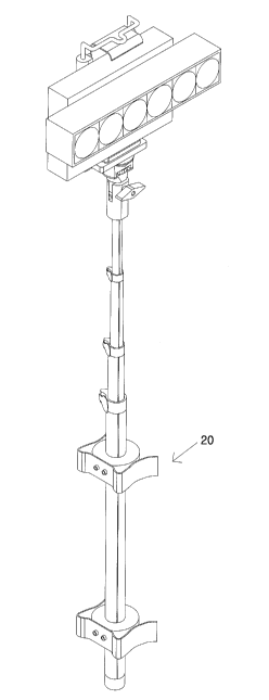
FIG. 1 is a perspective view of a vehicle emergency
safety device using a selfie stick, according to the
present invention.
FIG. 2 is a detailed perspective view of the vehicle
emergency safety device using the selfie stick, according
to the present invention.
FIG. 3 is a detailed perspective view of a flasher
according to the present invention.
7
CA 02985990 2017-11-14
FIG. 4 is a detailed perspective view of a fixing
clamp according to the present invention.
FIG. 5 is a perspective view showing how to use a
cradle and a joint according to the present invention.
[Best Mode]
The present invention provides a vehicle emergency
safety device using a selfie stick, the device including a
support stick 100 including first, second, third, and
fourth poles 110, 120, 130, and 140 having different
diameters and extendable to a desired length in a
telescopic manner by pulling out the second, third, and
fourth poles 120, 130, and 140 sequentially retracted into
the first pole 110 having the largest diameter,
two fixing clamps 20 provided at a lower part of the
support stick 100,
a joint 200 provided on the top of the support stick
100, a cradle 300 provided on the top of the joint 200 and
360 -rotatable by a second adjusting screw 260, and a
flasher 10 inserted into and fixed to the cradle 300. As
illustrated in FIGS. 1 and 2, the support stick 100 of the
vehicle emergency safety device includes the first, second,
third, and fourth poles 110, 120, 130, and 140 having
different diameters, and is used by pulling out the second,
third, and fourth poles 120, 130, and 140 sequentially
8
CA 02985990 2017-11-14
retracted into the first pole 110 having the largest
diameter, to a desired length in a telescopic manner,
fitting the flasher 10 into the cradle 300 provided on the
top of the fourth pole 140, attaching the device to a side
of a vehicle door using the two fixing clamps 20 provided
on the first pole 110, spaced apart from each other by a
certain distance, and including clips, and then adjusting
the joint 200 located between the fourth pole 140 and the
cradle 300.
[Mode of the Invention]
The present invention relates to a vehicle emergency
safety device using a selfie stick, the device including a
support stick 100 including first, second, third, and
fourth poles 110, 120, 130, and 140 having different
diameters and extendable to a desired length in a
telescopic manner by pulling out the second, third, and
fourth poles 120, 130, and 140 sequentially retracted into
the first pole 110 having the largest diameter,
two fixing clamps 20 provided at a lower part of the
support stick 100,
a joint 200 provided on the top of the support stick
100, a cradle 300 provided on the top of the joint 200 and
360 -rotatable by a second adjusting screw 260, and a
flasher 10 inserted into and fixed to the cradle 300.
9
CA 02985990 2017-11-14
As illustrated in FIGS. 1 and 2, the support stick
100 according to the present invention includes the first,
second, third, and fourth poles 110, 120, 130, and 140
having different diameters, and is used by pulling out the
second, third, and fourth poles 120, 130, and 140
sequentially retracted into the first pole 110 having the
largest diameter, to a desired length in a telescopic
manner, fitting the flasher 10 into the cradle 300
provided on the top of the fourth pole 140, attaching the
device to a side of a vehicle door using the two fixing
clamps 20 provided on the first pole 110, spaced apart
from each other by a certain distance, and including clips,
and then adjusting the joint 200 located between the
fourth pole 140 and the cradle 300.
The support stick 100 includes the first, second,
third, and fourth poles 110, 120, 130, and 140 and is
extendable to a desired length by retracting or extending
the second, third, and fourth poles 120, 130, and 140 into
or from the first pole 110 having the largest diameter.
The first, second, third, and fourth poles 110, 120,
130, and 140 have different diameters. That is, an upper
pole has a smaller diameter than a lower pole. Stoppers 2
are provided at upper ends of the first, second, and third
CA 02985990 2017-11-14
poles 110, 120, and 130 to fix the same after being
extended to a certain length.
As illustrated in FIGS. 1, 2, and 5, the joint 200
uses a conventional selfie stick joint and, specifically,
includes a fixing member 210 and a hinge member 220. The
fixing member 210 is provided at an end of the fourth pole
140, and a hinge member lower part 221 of the hinge member
220 is inserted into and fixed to a fixing member upper
recess 211 provided at an upper part of the fixing member
210.
A first adjusting screw 250 penetrates through the
fixing member upper recess 211 and the hinge member lower
part 221 inserted into the fixing member upper recess 211
in such a manner that an angle of the hinge member 220 is
adjustable only in one direction, e.g., a left-right
direction or a front-rear direction, by the first
adjusting screw 250.
A hinge member upper recess 222 is provided in the
top center of the hinge member 220, a hinge member central
side slot 223 is horizontally provided, and thus the
center of the hinge member 220 may rotate the cradle 300
provided on the top of the joint 200 by 360 and fix the
same using the horizontally provided hinge member central
side slot 223 and the second adjusting screw 260 provided
11
CA 02985990 2017-11-14
in the hinge member upper recess 222. As such, an
improvement in structure may be achieved.
As illustrated in FIGS. 1, 2, and 5, the cradle 300
is used to hold and fix the flasher 10 including a
plurality of light-emitting diodes (LEDs) or the like.
The cradle 300 according to the present invention
has a "c" shape, and a fixed grip 320 provided at a lower
part of a body plate 310 and a movable grip 330 provided
at an upper part of the body plate 310 are elastically
supported in directions toward each other in such a manner
that the flasher 10 is pressed and fixed between the fixed
grip 320 and the movable grip 330.
Specifically, the fixed grip 320 is integrally
provided at an end of the body plate 310, the movable grip
330 includes slidable bars 335 inserted into and
vertically slidable along two side grooves of the body
plate 310, and elastic means (not shown) for exerting
elastic force to move the movable grip 330 toward the
fixed grip 320 are provided in the two side grooves of the
body plate 310.
As illustrated in FIG. 4, each of the two fixing
clamps 20 inserted into and fixed to the support stick 100
and spaced apart from each other by a certain distance
12
CA 02985990 2017-11-14
includes a fixing ring 23 and a fixing clip 25 attached to
the outside of the fixing ring 23,
The first pole 110 is inserted into a through-hole
23-1 provided in the center of the fixing ring 23.
The fixing clip 25 provided outside the fixing ring
23 is attached and assembled to the fixing ring 23 using
bolts and nuts.
The fixing clips 25 provided on the fixing clamps 20
are fixed and attached to an end of the vehicle door. As
such, an improvement in structure may be achieved.
The present invention will now be described with
reference to the attached drawings.
FIG. 1 is a perspective view of a vehicle emergency
safety device using a selfie stick, according to the
present invention, FIG. 2 is a detailed perspective view
of the vehicle emergency safety device using the selfie
stick, according to the present invention, FIG. 3 is a
detailed perspective view of a flasher according to the
present invention, FIG. 4 is a detailed perspective view
of a fixing clamp according to the present invention, and
FIG. 5 is a perspective view showing how to use a cradle
and a joint according to the present invention.
FIGS. 1 to 5 illustrate stoppers 2, a flasher 10, a
13
CA 02985990 2017-11-14
battery case 11, a switch 12, fixing clamps 20, fixing
rings 23, through-holes 23-1, fixing clips 25, a support
stick 100, first, second, third, and fourth poles 110, 120,
130, and 140, a joint 200, a fixing member 210, a fixing
member upper recess 211, a hinge member 220, a hinge
member lower part 221, a hinge member upper recess 222, a
hinge member central side slot 223, a first adjusting
screw 250, a second adjusting screw 260, a cradle 300, a
body plate 310, a fixed grip 320, a movable grip 330, and
slidable bars 335.
In terms of structure, as illustrated in FIGS. 1 to
4, the vehicle emergency safety device using the selfie
stick, according to the present invention, includes
the support stick 100 including the first, second,
third, and fourth poles 110, 120, 130, and 140 having
different diameters and extendable to a desired length in
a telescopic manner by pulling out the second, third, and
fourth poles 120, 130, and 140 sequentially retracted into
the first pole 110 having the largest diameter,
two fixing clamps 20 provided at a lower part of the
support stick 100,
the joint 200 provided on the top of the support
stick 100, the cradle 300 provided on the top of the joint
14
CA 02985990 2017-11-14
200 and 360 -rotatable by the second adjusting screw 260,
and the flasher 10 inserted into and fixed to the cradle
300 and including the battery case 11 and the switch 12.
The support stick 100 includes the first, second,
third, and fourth poles 110, 120, 130, and 140 having a
pipe shape with grooves at two sides thereof, having
diameters sequentially reduced from the bottom to the top,
and retracted in a telescopic manner,
the stoppers 2 provided at uppermost parts of the
first, second, and third poles 110, 120, and 130, and
the two fixing clamps 20 provided on the first pole
110 and spaced apart from each other by a certain distance.
The fixing clamp 20 includes the fixing ring 23
having a through-hole in the center thereof, and the
fixing clip 25 fixed to the outside of the fixing ring 23
using bolts and nuts as illustrated in FIG. 4.
The joint 200 includes the fixing member 210 fixed
to an end of the fourth pole 140,
the hinge member lower part 221 inserted into and
fixed to the fixing member upper recess 211 provided at an
upper part of the fixing member 210, and having a through-
hole in the center thereof,
the first adjusting screw 250 penetrating through
CA 02985990 2017-11-14
the fixing member upper recess 211 and the hinge member
lower part 221,
the hinge member upper recess 222 provided in the
top center of the hinge member 220, the hinge member
central side slot 223 horizontally provided in the center
of the hinge member 220, and the second adjusting screw
260 provided in the hinge member central side slot 223 and
having an upper part provided in the hinge member upper
recess 222.
The cradle 300 has a "E" shape and includes
the body plate 310 having body plate grooves (not
shown) at two sides thereof, elastic means (not shown)
provided in lower parts of the body plate grooves (not
shown),
the fixed grip 320 provided at a lower part of the
body plate 310, and the movable grip 330 provided at an
upper part of the body plate 310 and including the
slidable bars 335 at two sides thereof.
In terms of usage, when an emergency occurs,
emergency lights are turned on and a vehicle stops.
The vehicle emergency safety device according to the
present invention is taken out of a safety box in a trunk
of the vehicle, and then the retracted support stick 100
16
CA 02985990 2017-11-14
of the vehicle emergency safety device is extended by
pulling out the first, second, third, and fourth poles 110,
120, 130, and 140 in a telescopic manner, and is fixed
using the stoppers 2.
The flasher 10 is mounted on the cradle 300 provided
on the top of the fourth pole 140 in such a manner that
the flasher 10 is pressed and fixed between the fixed grip
320 and the movable grip 330 of the cradle 300, and the
flasher 10 is switched on.
The fixing clips 25 of the two fixing clamps 20
provided on the first pole 110 of the support stick 100
and spaced apart from each other by a certain distance are
attached to an end of a vehicle door in such a manner that
the end of the vehicle door is inserted between the fixing
ring 23 and (one of) two sides of the fixing clip 25.
The flasher 10 faces backward by adjusting the joint
200 located between the fourth pole 140 and the cradle 300.
Thus, the stopped vehicle may be easily recognized by
other vehicles.
Thereafter, the vehicle emergency safety device may
be detached in reverse order of the above-described method.
As such, the vehicle emergency safety device may be used
when the vehicle is involved in an accident.
[Industrial Applicability]
17
CA 02985990 2017-11-14
A vehicle emergency safety device using a selfie
stick, according to the present invention, may be attached
to a vehicle door when a vehicle unavoidably stops due to
an accident, and may include
a support stick 100 including first, second, third,
and fourth poles 110, 120, 130, and 140 having different
diameters and extendable to a desired length in a telescopic
manner by pulling out the second, third, and fourth poles
120, 130, and 140 sequentially retracted into the first pole
110 having the largest diameter,
two fixing clamps 20 provided at a lower part of the
support stick 100,
a joint 200 provided on the top of the support stick
100, a cradle 300 provided on the top of the joint 200 and
360 -rotatable by a second adjusting screw 260, and a
flasher 10 inserted into and fixed to the cradle 300.
18