Note : Les descriptions sont présentées dans la langue officielle dans laquelle elles ont été soumises.
CART APPARATUSES WITH OPERABLE STEPS
FIELD
[0001] The present disclosure relates to cart apparatuses with operable
steps,
specifically cart apparatuses with steps that can be moved into and between an
inoperable
position and an operable position.
BACKGROUND
[0002] U.S. Patent No. 4.174,021 discloses a ladder truck for use in
stores for
transporting goods from central storage to display shelves and for
facilitating the loading of such
goods on display shelves. The ladder truck comprises a wheeled truck having
attached to one end
a stepladder.
[0003] U.S. Patent No. 5,170,529 discloses a wheel lock mechanism for
use in carts and
the like for releasably locking an opposed pair of swivel caster wheels of
such carts. The wheel
lock mechanism includes a lever arm extending outwardly from the cart operable
by the foot of
an operator for moving a locking mechanism between a wheel locking position
and a
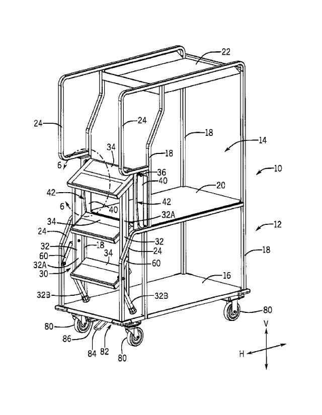
free-wheeling position.
100041 U.S. Patent No. 9,149,114 discloses a cabinet having a deep shelf
with limited
access and includes at least two opposite sides carrying track means to permit
easy adjustment
of the shelf between two or more levels by a single person maneuvering only
the one
accessible end of the shelf The cabinet can be mounted on wheels to form a
cart.
SUMMARY
[0005] This Summary is provided to introduce a selection of concepts
that are further
described herein below in the Detailed Description. This Summary is not
intended to identify
key or essential features of the claimed subject matter, nor is it intended to
be used as an aid
in limiting the scope of the claimed subject matter.
[0006] An example cart apparatus of the present disclosure includes a
frame that
defines a cavity and steps operably coupled to the frame. The steps are
movable into and
between an inoperable position in which the steps are nested in the cavity and
an operable
- 1 -
CA 2990682 2019-07-12
position in which the steps are at least partially outside the cavity. One of
the steps and the
frame has a guide pin, and the other of the steps and the frame defines a slot
in which the
guide pin is slideably received. The slot is configured to guide the steps
into and between the
inoperable position and the operable position as the guide pin slides in the
slot.
BRIEF DESCRIPTION OF THE DRAWINGS
[0007] This Summary is provided to introduce a selection of concepts
that are further
described below in the Detailed Description. This Summary is not intended to
identify key or
essential features of the claimed subject matter, nor is it intended to be
used as an aid in
limiting the scope of the claimed subject matter.
[0008] FIG. 1 is an example cart with steps in an inoperable position.
[0009] FIG. 2 is the cart of FIG. 1 with the steps in an operable
position.
[0010] FIG. 3 is a side view of the cart of FIG. 1.
[0011] FIG. 4 is a side view of the cart of FIG. 2.
[0012] FIG. 5 is an exploded view of the cart of FIG. 2.
[0013] FIG. 6 is an enlarged view within line 6-6 of FIG. 1.
[0014] FIG. 7 is an enlarged view within line 7-7 of FIG. 2.
[0015] FIG. 8 is an enlarged view within line 8-8 of FIG. 2.
[0016] FIG. 9 is a view like FIG. 8 showing a partial bottom view of
cart of FIG. 2.
[0017] FIG. 10 is a side view of a locking assembly in a disengaged
position.
[0018] FIG. 11 is a view like FIG. 10 with the locking assembly in an
engaged
position.
[0019] FIG. 12 is an enlarged view of an example plate having a slot. A
guide pin of
a roller assembly is positioned at a first end of the slot when the steps are
in the inoperable
position.
[0020] FIG. 13 is a view like FIG. 12 with the guide pin of the roller
assembly
positioned at a second end of the slot when the steps are in the operable
position.
[0021] FIG. 14 is a view like FIG. 12 with the guide pin of the roller
assembly
positioned in a middle portion of the slot when the steps are in a locked
position.
- 2 -
CA 2990682 2019-07-12
DETAILED DESCRIPTION OF THE DRAWINGS
[0022] In the present description, certain terms have been used for
brevity, clarity, and
understanding. No unnecessary limitations are to be inferred therefrom beyond
the
requirement of the prior art because such terms are used for descriptive
purposes only and are
intended to be broadly construed. The different apparatuses described herein
may be used
alone or in combination with other apparatuses. Various equivalents,
alternatives, and
modifications are possible within the scope of the appended claims.
[0023] Movable storage or stocking carts are typically utilized by
businesses to
transport objects (e.g. merchandise, saleable items, equipment, marketing
materials) within a
building. The present inventors have recognized that as an operator (e.g.
employee) moves a
cart through the building, the operator often carries separate steps with
them. These separate
and "loose" steps can be accidentally dropped or can accidentally bump other
objects (e.g.
walls, staged merchandise, customers) thereby causing bodily injury and/or
damage.
Accordingly, through research and development the present inventors have
developed the cart
of the present disclosure that includes steps which are operably connected to
the cart.
Furthermore, the cart of the present disclosure permits the steps to be moved
within the cart
when the steps are not in use.
[0024] FIGS. 1-9 depict an example cart 10 of the present disclosure
that is for moving
materials and objects (e.g. boxes). The cart 10 includes a frame 12 that
defines a cavity 14 in
which objects can be placed. The frame 12 comprises a base 16 and a plurality
of support
members 18 that extend from the base 16. The frame 12 further includes a shelf
20 disposed
in the cavity 14 vertically above the base 16. The base 16 has a horizontal
depth (H1 on FIG.
4) that is greater than the horizontal depth of the shelf 20 (H2 on FIG. 4).
That is, the depth of
the base 16 (H1 on FIG. 4) is greater than the depth of the shelf 20 (H2 on
FIG. 4).
[0025] A top 22 is positioned vertically above the shelf 20. The shelf
20 and the top
22 are coupled to the support members 18 such that objects placed on the shelf
20 and/or the
top 22 are vertically supported thereon, respectively. To increase the
stability of the cart 10,
the top 22 has a horizontal depth (H3 on FIG. 4) that is less than the
horizontal depth of the
shelf 20 (H2 on FIG. 4). The frame 12 includes handles 24 that can be grasped
by an operator
to move and maneuver the cart 10.
- 3 -
CA 2990682 2019-07-12
[0026] Steps 30 are coupled to the frame 12 such that the steps 30 are
movable into
and between an inoperable position in which the steps 30 are nested in the
cavity 14 (FIGS. 1
& 3) and an operable position in which the steps 30 are at least partially
outside of the cavity
14 and the frame 12 (FIGS. 2 & 4). The steps 30 include a pair of opposing
legs 32 and a
plurality of treads 34 that extend between the opposing legs 32. The opposing
legs 32 and the
treads 34 are fixedly coupled to each other, and each opposing leg has an
upper or first section
32A and a lower or second section 32B that extends transverse to the first
section 32A. While
in the inoperable position (FIGS. 1 & 3), the steps 30 are vertically directly
above the base 16.
The uppermost tread 34 of the steps 30 aligns (i.e. is flush) with the shelf
20 of the frame 12
when the steps 30 are in the operable position (FIGS. 2 & 4). The uppermost
tread 34 has a
horizontal depth (H4 on FIG. 4), and the horizontal depth of the uppermost
tread 34 (H4 on
FIG. 4) and the horizontal depth of the shelf 20 (H2 on FIG. 4) equate to the
horizontal depth
of the base 16 (H1 on FIG. 4). That is, the length of the uppermost tread 34
(H4 of FIG. 4)
added with the length of the shelf 20 (H2 on FIG. 4) equals the length of the
base 16 (H1 on
FIG. 4).
[0027] The steps 30 include a guide pin 36 that is slidable (i.e.
slidably received) in a
slot 42 defined by a plate 40 which may be part of the frame 12. The slot 42
is configured to
guide the steps 30 into and between the inoperable position (FIGS. 1 & 3) and
the operable
position (FIGS. 2 & 4) as the steps 30 are moved by the operator and/or as the
guide pin 36
slides in the slot 42. In certain examples, the plate 40 is positioned within
the cavity 14.
[0028] The slot 42 has a first end 44 (FIG. 6) that receives and retains
the guide pin
36 when the steps 30 are in the inoperable position (FIGS. 1 & 3) and a second
end 46 (FIG.
6) opposite the first end 44 that receives the guide pin 36 when the steps 30
are in the operable
position (FIGS. 2 & 4). The second end 46 is disposed vertically directly
below the first end
44.
[0029] The steps 30 are configured to move from the inoperable position
(FIGS. 1, 3,
& 6) to the operable position (FIGS. 2, 4, & 7) when the operator applies a
force (i.e. a lifting
force, pulling force, rotational force, and/or a combination force thereof) to
the steps 30 such
that the guide pin 36 slides away from the first end 44 and through upper
portion 43A (FIG.
- 4 -
CA 2990682 2019-07-12
6) of the slot 42 toward the second end 46. The upper portion 43A is
positioned between the
first end 44 and the second end 46 and disposed vertically above the first end
44 of the slot 42
such that the guide pin 36 vertically upwardly slides through the upper
portion 43A and then
vertically downwardly moves toward the second end 46 as the steps 30 move from
the
inoperable position (FIGS. 1, 3, & 6) to the operable position (FIGS. 2, 4, &
7). That is, the
guide pin 36 vertically downwardly slides through a middle portion 43B (FIG.
6) and a lower
portion 43C (FIG. 6) of the slot 42 toward the second end 46 as the steps 30
are moved from
the inoperable position (FIGS. 1, 3, & 6) to the operable position (FIGS. 2,
4, & 7). The guide
pin 36 is configured to slide through the middle portion 43B and the lower
portion 43C toward
the second end 46 under force of gravity when the steps 30 are moved from the
inoperable
position (FIGS. 1 & 3) to the operable position (FIGS. 2 & 4).
[0030] When the steps 30 are moved in the opposite direction, i.e. the
steps 30 are
moved from the operable position (FIGS. 2, 4, & 7) to the operable position
(FIGS. 1, 3, &
6), the guide pin 36 vertically upwardly slides from the second end 46 through
the lower
portion 43C and the middle portion 43B toward the first end 44. The guide pin
36 is configured
to slide through the upper portion 43A to the first end 44 under force of
gravity when the steps
30 are moved from the operable position (FIGS. 2, 4, & 7) to the inoperable
position (FIGS.
1, 3, & 6).
[0031] Referring specifically to FIGS. 12 and 13, the upper portion 43A
is positioned
between the first end 44 and the second end 46. The upper portion 43A is
sloped (i.e. the upper
portion 43A is vertically upwardly sloped) such that the upper portion 43A has
a maximum
point 45 that is vertically above the first end 44. The lower portion 43C is
vertically below the
upper portion 43A and extends horizontally away from the second end 46 of the
slot 42 such
that the steps 30 horizontally outwardly moves relative to the frame 12 (FIGS.
3-4) when the
guide pin 36 slides through the lower portion 43C. The lower portion 43C is
sloped (i.e. the
lower portion 43C is vertically downwardly sloped). The middle portion 43B
extends from
and is transverse to the upper portion 43A and the lower portion 43C. The
middle portion 43B
is horizontally outwardly curved from the first and second ends 44, 46 and/or
the frame 12
(FIGS. 3-4) (i.e. the middle portion 43B is "bowed" outwardly away from the
frame 12).
- 5 -
CA 2990682 2019-07-12
[0032] The slot 42 and the cart 10 are further configured to prevent
inadvertent
movement of the steps 30 from the inoperable position (FIGS. 1 & 3) to the
operable position
(FIGS. 2 & 4). Specifically, the steps 30 are configured to move to a locked
position (not
shown) between the inoperable position (FIGS. 1 & 3) and the operable position
(FIGS. 2 8c
4) when a jostling force (e.g. a force that results from the cart 10 being
jostled or rolling over
a bump) acts on the steps 30. When the steps 30 are in the locked position,
the guide pin 36 is
trapped in the slot 42 (see FIG. 14; e.g. the guide pin 36 is trapped in the
middle portion 43B
(FIG. 6) of the slot 72) and the opposing legs 32 of the steps 30 rest on the
base 16 (similar to
position of the opposing legs 32 on the base 16 as shown in FIG. 3 when the
steps 30 are in
the inoperable position). That is, the jostling force may cause the guide pin
36 to vertically
upwardly slide from the first end 44, through the upper portion 43A past the
maximum point
45, and into the middle portion 43B where the guide pin 36 becomes trapped
(i.e. is prevented
from further moving toward the second end 46 due to the positioning of the
guide pin 36 and
the legs 32 relative to each other) and the opposing legs 32 rest on the base
16 (FIG. 3).
Accordingly, the steps 30 remain in the locked position until the operator
applies a force to
the steps 30 to thereby move the steps 30 to the inoperable position (FIGS. 1
& 3) or the
operable position (FIGS. 2 & 4). The ability of the steps 30 to move to the
locked position
when a jostling force acts on the steps 30 prevents injury to the operator
and/or damage to
nearby objects.
[0033] In certain examples, the guide pin 36 is part of a roller
assembly 70 that rolls
relative to the slot 42 as the steps 30 move into and the between the
inoperable position (FIGS.
1 & 3) to the operable position (FIGS. 2 & 4). The roller assembly 70 includes
at least one
washer (not shown) that is configured to prevent excessive lateral movement of
the guide pin
38 and/or the steps 30 relative to the slot 42 and/or frame 12, respectively.
[0034] The cart 10 includes a hinge member 60 that is pivotally coupled
to the frame
12 and the steps 30 and configured to guide the steps 30 into and the between
the inoperable
position (FIGS. 1 & 3) and the operable position (FIGS. 2 & 4). The hinge
member 60 is
further configured to limit rotational movement of the steps 30 such that the
steps 30 primarily
translate as the steps 30 move into and between the inoperable position (FIGS.
1 & 3) and the
- 6 -
CA 2990682 2019-07-12
operable position (FIGS. 2 & 4). The hinge member 60 pivots at least 90
degrees relative to
the handle 24 and/or the frame 12 when the steps 30 are moved into and between
the
inoperable position (FIGS. 1 & 3) and the operable position (FIGS. 2 & 4). The
hinge member
60 extends from the cavity 14 when the steps 30 are in the operable position
(FIGS. 2 & 4),
and the hinge member 60 is positioned in the cavity when the steps 30 are in
the inoperable
position (FIGS. 1 & 3).
[0035] Referring to FIGS. 8-11, the cart 10 includes a plurality of
caster wheels 80
that enable horizontal movement of the cart 10. The number, type, and
configuration of caster
wheels 80 relative to the frame 12 can vary from that which is shown. In the
depicted example,
the caster wheels 80 are coupled to the base 16.
[0036] The cart 10 includes a locking assembly 82 disposed vertically
directly below
the steps 30 such that the locking assembly 82 can be selective activated by
an operator to
thereby prevent movement of at least one of the plurality of caster wheels 80
prior to moving
the steps 30 into and between the inoperable position (FIGS. 1 & 3) and the
operable position
(FIGS. 2 & 4). The locking assembly 82 includes a first pedal 84 and a second
pedal 86. In
operation, the first pedal 84 is depressed by the operator (i.e. the operator
vertically
downwardly presses the first pedal 84) which causes the locking assembly 82 to
engage the
caster wheels 80 and thereby "lock" movement of the caster wheels 80 such that
the caster
wheels 80 cannot freely rotate. The operator disengages the locking assembly
82 by applying
a lifting force to the second pedal 86 (i.e. the operator uses a foot to
vertically lift up on the
second pedal 86) which allows the caster wheel 80 to rotate freely. The
locking assembly 82
is rendered inaccessible, including blocked, to the operator when the steps
are in the operable
position (FIGS. 2 & 4) such that the locking assembly 82 cannot be
inadvertently disengaged
and/or the caster wheels 80 "unlocked" when the steps are in the operable
position (FIGS. 2
& 4). Reference is made the above mentioned U.S. Patents for further
description of example
conventional locking assemblies and operation thereof.
- 7 -
CA 2990682 2019-07-12