Note : Les descriptions sont présentées dans la langue officielle dans laquelle elles ont été soumises.
CA 02992701 2018-01-16
WO 2017/033067
PCT/1B2016/052516
1
OPTICAL COHERENCE TOMOGRAPHY GUIDED EPIRETINAL
MEMBRANE PEELING
FIELD
[0001] The present disclosure relates generally to improved visualization
for ophthalmic surgeries and, more particularly, to optical coherence
tomography guided epiretinal membrane peeling.
BACKGROUND
[0002] An epiretinal membrane (ERM) is a thin sheet of fibrous tissue that
can form on the macula and may act like a film through which it is harder to
see. The film may also contract like scar tissue, which can pull on the
retina.
ERM can cause various retinal pathologies, including retinal folds, retinal
distortion, cystoids, macular edema, and small hemorrhages.
[0003] Currently, the only way to treat ERM is surgical removal through
vitrectomy. In such a procedure, a vitreoretinal surgeon uses extremely fine
forceps, under high magnification, to grasp and gently peel away the
membrane from the retina (often referred to as "ERM peeling"). However,
visualization of ERM may be difficult due to its thin and translucent nature,
making ERM peeling a challenging procedure. One proposed technique to
facilitate better visualization involves staining the ERM with vital dyes
(e.g.,
Trypan Blue, ICG). However, the potential toxicity of these dyes to retina
cells
is still unclear and, as a result, this technique remains controversial.
[0004] Accordingly, there remains a need for improved visualization of
ERM during an ERM peeling procedure. Certain embodiments of the present
disclosure may address this need.
CA 02992701 2018-01-16
WO 2017/033067
PCT/IB2016/052516
2
SUMMARY
[0005] In certain embodiments, an ERM visualization system includes an
OCT system operable to generate an OCT image of a region of a patient's
eye, the region of the patient's eye including an ERM. The ERM visualization
system further includes an image processing unit operable to process the
OCT image to identify the ERM by differentiating the ERM from other
structures within the region of the patient's eye and generate an ERM map
depicting one or more characteristics (including at least a location of a
portion
of the ERM within the region of the patient's eye) of the identified ERM. The
ERM visualization system further includes a display operable to display the
ERM map.
[0006] Certain embodiments of the present disclosure may provide one or
more technical advantages. For example, because the transparent nature of
ERM may make it difficult to locate, displaying an OCT-based ERM map to a
surgeon may allow the surgeon to better visualize the location and
characteristics of the ERM during an ERM peeling procedure. As a result,
embodiments of the present disclosure may allow for more complete ERM
removal while decreasing the risk of damage to the underlying structures of
the patient's eye.
CA 02992701 2018-01-16
WO 2017/033067
PCT/IB2016/052516
3
BRIEF DESCRIPTION OF THE DRAWINGS
[0007] For a more complete understanding of the present disclosure and
the advantages thereof, reference is now made to the following description
taken in conjunction with the accompanying drawings in which like reference
numerals indicate like features and wherein:
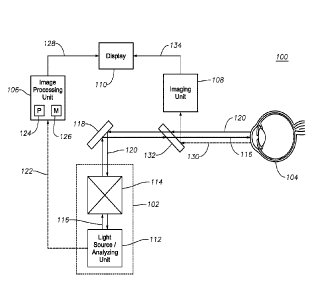
[0008] FIG. 1 illustrates an exemplary ERM visualization system
facilitating
OCT-guided ERM peeling, according to certain embodiments of the present
disclosure; and
[0009] Figs. 2A-2F illustrate exemplary ERM maps generated by the ERM
visualization system depicted in FIG. 1, according to certain embodiments of
the present disclosure.
[0010] The skilled person in the art will understand that the drawings,
described below, are for illustration purposes only. The drawings are not
intended to limit the scope of the applicant's disclosure in any way.
CA 02992701 2018-01-16
WO 2017/033067
PCT/IB2016/052516
4
DETAILED DESCRIPTION
[0011] For the purposes of promoting an understanding of the principles of
the present disclosure, reference will now be made to the embodiments
illustrated in the drawings, and specific language will be used to describe
the
same. It should nevertheless be understood that no limitation of the scope of
the disclosure is intended. Any alterations and further modifications to the
described systems, devices, and methods, and any further application of the
principles of the present disclosure are fully contemplated as would normally
occur to one skilled in the art to which the disclosure relates. In
particular, it is
fully contemplated that the systems, devices, and/or methods described with
respect to one embodiment may be combined with the features, components,
and/or steps described with respect to other embodiments of the present
disclosure. For the sake of brevity, however, the numerous iterations of these
combinations will not be described separately. For simplicity, in some
instances the same reference numbers are used throughout the drawings to
refer to the same or like parts.
[0012] In general, the present disclosure may provide an ERM
visualization system that includes an OCT system operable to generate an
OCT image of at least a portion of the eye (e.g., the area near the retina)
and
an image processing unit operable to process that OCT image to facilitate
ERM visualization. For example, the image processing unit may process the
OCT image to identify the location of the ERM, the thickness of the ERM, the
gap between the ERM and the underlying structures of the eye, and/or
contractions caused by the ERM. Based on this information, a display may be
generated and displayed to a surgeon that includes an ERM map to guide the
surgeon in performing an ERM peeling procedure.
[0013] FIG. 1 illustrates an exemplary ERM visualization system 100
facilitating OCT-guided ERM peeling, according to certain embodiments of the
present disclosure. In general, ERM visualization system 100 includes an
OCT system 102 for generating OCT images of a patient's eye 104 and an
image processing unit 106 for processing the OCT image generated by OCT
system 102 in order to determine characteristics of the ERM in the patient's
eye 104. ERM visualization system 100 may further include an imaging unit
CA 02992701 2018-01-16
WO 2017/033067
PCT/IB2016/052516
108 operable to generate images of the patient's eye during surgery and a
display 110 for displaying an ERM map generated based on the
characteristics of the ERM determined by image processing unit 106. For
example, display 110 may display a video image of the patient's eye
generated by imaging unit 108 along with an ERM map overlay including
characteristics of the ERM determined based on the OCT image. As another
example, display 110 may be a projection unit coupled to a surgical
microscope (e.g., a heads-up-display) such that the ERM map may be
displayed within the field of view of the surgical microscope.
[0014] Although the various components of system 100 are depicted and
described as being part of a single system, the present disclosure
contemplates that those components may be divided among any suitable
number of systems, according to particular needs. As just one example, OCT
system 102 and image processing unit 106 may each be part of a pre-
operative imaging system, while imaging unit 108 and display 110 may be
used during surgery (with the ERM map determined preoperatively imported,
registered, and overlaid on the live image generated by imaging unit 108 and
displayed on display 110).
[0015] OCT system 102 may include a light source/analyzing unit 112 and
a beam scanner 114. In general, light source/analyzing unit 112 may
generate an OCT imaging beam 116 and beam scanner 114 may direct the
generated OCT imaging beam 116 to a particular region within the patient's
eye 104. Reflections of the OCT imaging beam 116 from the particular region
within the patient's eye 104 may return to light source/analyzing unit 112
along the same optical path as OCT imaging beam 116, and light
source/analyzing unit 112 may generate OCT images of the particular region
by determining interference between the reflections and a reference arm of
the OCT imaging beam 116. The present disclosure contemplates that OCT
system 110 may include any suitable additional optical components for
manipulating OCT imaging beam 116 as would be understood by those of skill
in the art, and those additional components are not depicted/described for the
sake of simplicity.
CA 02992701 2018-01-16
WO 2017/033067
PCT/IB2016/052516
6
[0016] In certain embodiments, the OCT imaging beam 116 may comprise
a visible, an infrared, or near infrared light beam covering a relatively
narrow
band of wavelengths (e.g., 400nm ¨ 700nm, 830nm - 870nm, 790nm -
900nm, 950nm-1150nm). However, an OCT imaging beam 116 having any
suitable spectral range may be used. The OCT imaging beam 116 may pass
through beam scanner 114 (described in further detail below) along with any
other suitable optical components of OCT system 102 (not depicted, as
described above). OCT imaging beam 116 may then be directed to the
patient's eye 104, such as by a mirror 118 operable to reflect light falling
within the spectral range of the OCT imaging beam 116.
[0017] Beam scanner 114 may comprise any suitable optical component or
combination of optical components facilitating focusing of the OCT imaging
beam 116 in the X-Y plane. For example, beam scanner 114 may include
one or more of a pair of scanning mirrors, a micro-mirror device, a MEMS
based device, a deformable platform, a galvanometer-based scanner, a
polygon scanner, and/or a resonant PZT scanner. In certain embodiments,
the position of the optical components of beam scanner 114 may be
manipulated in an automated manner. As just one example, beam scanner
114 may comprise a pair of scanning mirrors each coupled to a motor drive,
the motor drives operable to rotate the mirrors about perpendicular axes. As
a result, by controlling the position of the coupled motors (e.g., according
to a
pre-determined or selected scan pattern), the X-Y positioning of OCT imaging
beam 116 within the patient's eye 104 can be controlled. Additionally, the
depth of focus of the OCT imaging beam 116 may be controlled by one or
more other components of OCT system 102 as is understood in the art in
order to facilitate 3-D OCT imaging.
[0018] A portion of the OCT imaging beam 116 reaching the patient's eye
104 may be reflected by the patient's eye (reflected OCT beam 120).
Reflected OCT beam 120 may return to OCT system 102 along substantially
the same optical path as traveled by OCT imaging beam 116. Once reflected
OCT beam 120 reaches light source/analyzing unit 112, light source/analyzing
unit 112 may construct an OCT image (A-scan) based on interference
between the reflected OCT beam 120 and a reference arm of OCT imaging
CA 02992701 2018-01-16
WO 2017/033067
PCT/IB2016/052516
7
beam 116 (as is known in the art). Moreover, by moving the imaging beam in
the X-Y plane via beam scanner 114 and/or changing the depth of focus of
the imaging beam 114, a plurality of OCT images (A-scans) may be
generated and combined into an OCT cross sectional image (B-scan), and a
plurality of those cross sectional images (B-scans) may be combined to
generate a 3-D OCT image.
[0019] The OCT image(s) generated by OCT system 102 (identified in FIG.
1 by reference numeral 122), which may include an A-scan, a B-scan, or a 3-
D OCT image constructed by combining a plurality of B-scans as described
above, may be communicated to image processing unit 106. In general,
image processing unit 106 may analyze the received OCT images 122 to
identify any ERM depicted in those images. Based on that analysis, image
processing unit 106 may generate an ERM map to be displayed to a surgeon
to assist in an ERM peeling procedure.
[0020] Image processing unit 106 may include any suitable combination of
hardware, firmware, and software. In certain embodiments, image processing
unit 106 may include a processing module 124 and a memory module 126.
Processing module 124 may include one or more microprocessors, field-
programmable gate arrays (FPGAs), controllers, or any other suitable
computing devices or resources. Processing module 124 may work, either
alone or with other components of ERM visualization system 100, to provide
the functionality described herein. Memory module 126 may take the form of
volatile or non-volatile memory including, without limitation, magnetic media,
optical media, random access memory (RAM), read-only memory (ROM),
removable media, or any other suitable memory component.
[0021] Image processing unit 106 may be programmed to (or may store
software in memory module 126 that, when executed by processing module
124, is operable to) process the OCT images 122 generated by OCT system
102 to identify the location and/or characteristics of the ERM depicted in
those
images. For example, image processing unit 106 may process the OCT
images 122 to differentiate ERM from the underlying structures of the eye
(e.g., the retina). Because ERM may reflect OCT imaging beam 116
differently than the underlying structures, the ERM may be depicted
differently
CA 02992701 2018-01-16
WO 2017/033067
PCT/IB2016/052516
8
in OCT images 122 (e.g., as a brighter region of the images) and thus may be
differentiated from those underlying structures by image processing unit 106.
[0022] Having identified the ERM in the OCT images 122, image
processing unit 106 may be further operable to construct an ERM map
illustrating particular features of the ERM. For example, the ERM map may
identify the edge of the ERM, contractions caused by the ERM, the thickness
of the ERM, gaps between the ERM and the underlying structures of the eye,
or any other suitable aspects of the ERM. Exemplary ERM maps are
depicted in FIGS. 2A-2F, described in further detail below.
[0023] In certain embodiments, image processing unit 106 may be
communicatively coupled (via wired or wireless communication) to display
110, and image processing unit 106 may communicate generated ERM maps
(identified in FIG. 1 by reference numeral 128) to display 110 such that they
may be displayed to a surgeon during an ERM peeling procedure. Display
110 may include any suitable display device, such as flat panel monitor
operable to display still of live video images. For example, display 110 may
display a live video image generated by imaging unit 108 with an overlaid
ERM map 128 (as described in further detail below). Additionally or
alternatively, display device 110 may include a projection unit coupled to the
optics of a surgical microscope such that the ERM map may be displayed in
the surgeon's field of view through the microscope.
[0024] In certain embodiments, ERM visualization system 100 may
additionally include an imaging unit 108, which may include any suitable
device for generating an image of a patient's eye 104. Additionally, imaging
unit 108 may include any suitable magnification and focusing optics (not
depicted) for generating any suitable image of the patient's eye. As a
simplified example, visible or near infrared light 130 from the patient's eye
104
may be directed toward imaging unit 108 via a mirror 132 operable to reflect
or partially reflect wavelengths in the visible or near infrared spectrum
while
allowing passage of OCT imaging beam 116 and reflected OCT beam 120. In
certain embodiment, the generated images may be discrete still photographs
of the patient's eye 104. In other embodiment, the generated images may
comprise a continuous video stream of the patient's eye 104. Example
CA 02992701 2018-01-16
WO 2017/033067
PCT/IB2016/052516
9
imaging units may include digital video cameras, line scan ophthalmoscopes
or confocal-scanning ophthalmoscopes.
[0025] In certain embodiments, imaging unit 108 may be communicatively
coupled (via wired or wireless communication) to display 110, and imaging
unit 108 may communicate generated images of the patient's eye 104
(identified in FIG. 1 by reference numeral 134) to display 110 such that they
may be displayed to a surgeon. As described above, the ERM map 128
generated by image processing unit 106 may also be communicated to
display 110 and overlaid on the image 134 generated by imaging unit 108. As
one example, image 134 may be a live video image and ERM map 128 may
be a static ERM map generated based on an earlier (pre-surgical or intra-
surgical) OCT scan, the static ERM map 128 being displayed as overlaid on
the relevant portion of live video image 134. Moreover, the static ERM map
128 may track the live video image 134 by correlating relevant structures of
the eye 104 between the ERM map 128 and the live video image 134. In
some embodiment, imaging unit 108 may communicate generated images of
the patient's eye 104 directly to the image processing unit 106 to generate a
combined or composite image with the ERM map information, which is then
communicated to the display 110.
[0026] In certain embodiments, the displayed ERM maps 128 may be
continuously or periodically updated during the ERM peeling procedure. For
example, continuous OCT scanning may facilitate real-time updating of the
ERM map (or a portion thereof) displayed via display 110. As another
example, all or a portion of the original OCT image 122 may be updated
periodically (e.g., in automated manner or at the surgeons request), resulting
in corresponding updates to the generated ERM map 128. In either case, the
original OCT image 122 may be updated only in the region in which the
surgeon is working (e.g., by tracking the surgeon's instrument and imaging
only an area surrounding the instrument), with corresponding updates to the
ERM map 128 generated by image processing unit 106.
[0027] By displaying an ERM map to a surgeon (via display 110 or by
projecting the ERM map into the surgical microscope, as described above),
ERM visualization system 100 may facilitate better visualization of ERM
CA 02992701 2018-01-16
WO 2017/033067
PCT/IB2016/052516
during an ERM peeling procedure. As a result, ERM visualization system 100
may allow for more complete ERM removal while decreasing the risk of
damage to the underlying structures of the patient's eye 104.
[0028] Figs. 2A-2F illustrate exemplary ERM maps 200a-200f generated
by ERM visualization system 100, according to certain embodiments of the
present disclosure. In the illustrated embodiments, ERM maps 200a-200f are
depicted as overlaid on a relevant portion of a fundus image generated by
imaging unit 108, as discussed above.
[0029] More particularly, ERM map 200a (depicted in FIG. 2A) depicts the
outline of the ERM edge, which may help a surgeon locate an appropriate
starting point for ERM peeling procedure.
[0030] ERM map 200b (depicted in FIG. 2B) depicts the area in which the
ERM is located in a semi-transparent manner, effectively providing a digital
staining without the need to use dyes that may be toxic to the retina. Like
the
edge depicted in ERM map 200a, displaying ERM map 200b ay help a
surgeon locate an appropriate starting point for ERM peeling procedure.
[0031] ERM map 200c (depicted in FIG. 2C) depicts a contraction pattern
202c (with contraction centers 204c) caused by the ERM. The depicted
contraction centers 204c may indicate locations where the ERM is tightly
attached to the retina and may be high risk zones for the ERM peeling
procedure.
[0032] ERM maps 200d and 200e (depicted in FIG. 2D and FIG 2E,
respectively) each illustrate gaps between the ERM and the underlying
structures of the patient's eye (e.g., the retina). In particular, ERM map
200d
represents the size of the gap using contour lines while ERM map 200d
represents the size of the gap using shading. Because it may be desirable to
begin the ERM peeling procedure at locations having a maximum gap
between the EMR and the retina, ERM maps 200d and 200e may provide a
useful guide in starting the ERM peeling procedure.
[0033] Finally, ERM map 200f (depicted in FIG. 2F) depicts the thickness
of the ERM. Because it may be desirable to begin the ERM peeling
11
procedure at locations having a maximum ERM thickness, ERM maps 200f may
provide a useful guide in starting the ERM peeling procedure.
[0034] Although
FIGS 2A-2F illustrate alternative depictions of an ERM map,
the present disclosure contemplates that those alternative depictions may be
combined in any suitable manner.
Moreover, the present disclosure
contemplates that ERM visualization system 100 may be capable of generating
each of the ERM maps depicted in FIGS 2A-2F (or any suitable combination
thereof) such that the surgeon may select a desired ERM map to be displayed.
[0035] It will
be appreciated that various of the above-disclosed and other
features and functions, or alternatives thereof, may be desirably combined
into
many other different systems or applications. It will also be appreciated that
various presently unforeseen or unanticipated alternatives, modifications,
variations or improvements therein may be subsequently made by those skilled
in the art.
Date Recue/Date Received 2022-07-04