Note : Les descriptions sont présentées dans la langue officielle dans laquelle elles ont été soumises.
CA 02995257 2018-02-09
WO 2017/025096
PCT/DK2016/050262
1
AN ASSEMBLY COMPRISING AN END-FITTING AND AN UNBONDED FLEXIBLE
PIPE
The present invention relates to an assembly comprising an end-fitting and
an unbonded flexible pipe having a length and a longitudinal axis, said
flexible pipe comprising, from the inside and out, an internal armour layer,
an
internal pressure sheath, at least one external armour layer and an outer
sheath, the first end of the unbonded flexible pipe being terminated in the
end-fitting, and the end-fitting comprises means for connecting the internal
armour layer to an external electric power source.
TECHNICAL FIELD
Unbonded flexible pipes are frequently used as flexible risers or flexible
flowlines for the transport of fluid hydrocarbons such as oil and gas.
Moreover, unbonded flexible pipes are often used e.g. as riser pipes or
flowlines in the production of oil or other subsea applications.
The unbonded flexible pipes are constructed from a number of non-bonded
layers, such as helically laid steel and polymeric layers formed around a
central bore for transporting fluids. A typical unbonded flexible pipe
comprises, from the inside and outwards, an inner armouring layer known as
zo the carcass, an internal pressure sheath surrounded by one or more
armouring layers, such as pressure armouring and tensile armouring, and an
outer sheath. Thus, the internal pressure sheath forms a bore in which the
fluid to be transported is conveyed, i.e. the inner surface of the internal
pressure sheath facing the carcass forms the bore.
The armouring layers comprise or consist of multiple elongated armouring
elements that are not bonded to each other directly or indirectly via other
layers along the pipe. Thereby, the pipe becomes bendable and sufficiently
CA 02995257 2018-02-09
WO 2017/025096
PCT/DK2016/050262
2
flexible to roll up for transportation. The armouring elements are very often
manufactured from metallic and electrically conductive material.
Flexible unbonded pipes of the present type are for example described in the
standard "Recommended Practice for Flexible Pipe", ANSI/API 17 B, fourth
Edition, July 2008, and the standard "Specification for Unbonded Flexible
Pipe", ANSI/API 17J, Third edition, July 2008. As mentioned such pipes
usually comprise an innermost sealing sheath ¨ often referred to as an
internal pressure sheath, which forms a barrier against the outflow of the
fluid which is conveyed in the bore of the pipe, and one or usually a
plurality
io of armouring layers. Normally the pipe further comprises an outer
protection
layer, often referred to as the outer sheath, which provides mechanical
protection of the armour layers. The outer protection layer may be a sealing
layer sealing against ingress of sea water. In certain unbonded flexible pipes
one or more intermediate sealing layers are arranged between armour layers.
In general flexible unbonded pipes are expected to have a lifetime of 20
years or more in operation.
The meaning of the term "unbonded" in this text is that at least two of the
layers including the armouring layers and polymer layers are not bonded to
each other. In practice the known pipe normally comprises at least two
zo armouring layers located outside the internal pressure sheath and
optionally
an armour structure located inside the internal pressure sheath, which inner
armour structure normally is referred to as the carcass.
An unbonded flexible pipe is terminated by an end-fitting in which the
individual layers of the unbonded flexible pipe are fixed. The end-fitting
comprises a flange or similar means which makes it possible to connect the
end-fitting to other connectors, e.g. on a production platform or a well.
In recent years considerable research efforts have been put into flexible
unbonded pipes equipped with heating systems, such as electric heating. The
electric heating system may utilize the metallic armour layers in the
CA 02995257 2018-02-09
WO 2017/025096
PCT/DK2016/050262
3
unbonded flexible pipe. Such pipes are terminated in both ends using end-
fittings designed to withstand the mechanical and thermal loads put on the
pipe. Successful systems utilizing electric heating of the unbonded flexible
pipe require that the end-fitting is equipped with means for electrical
connection, hence, the end-fitting should be adapted for operating with
electricity, such as comprising electrical wiring.
DISCLOSURE OF INVENTION
An object of the present invention is to provide an improved assembly
io comprising an end-fitting and an unbonded flexible pipe allowing the
heating
system in the unbonded flexible pipe to receive electric power from an
external power source.
The present invention relates to an assembly comprising an end-fitting and
an unbonded flexible pipe. The unbonded flexible pipe has a length and a
longitudinal axis and a first and a second end. The flexible pipe comprises
from the inside and out;
an internal armour layer,
an internal pressure sheath,
at least one external armour layer and an outer sheath, and the first end of
zo the unbonded flexible pipe being terminated in the end-fitting in a pipe-
end.
Opposite to the pipe-end the end-fitting has a flange-end comprising a flange
for connection to a connector, and the end-fitting comprises an annular
channel next to the flange in the direction of the pipe-end. The end-fitting
further comprises means for connecting the internal armour layer to an
external electrical power source, the means for connecting comprises
connection points to the internal armour layer in the unbonded flexible pipe
and connection points to the electrical power source wherein the connection
CA 02995257 2018-02-09
WO 2017/025096
PCT/DK2016/050262
4
points for the electrical power source are mounted in a housing adapted to an
outer surface-part in the annular channel of the end-fitting.
End-fittings are well-known in the technical field of unbonded flexible pipes,
in which it is also well-known how to terminate an unbonded flexible pipe in
an end-fitting.
At one end the end-fitting comprise a flange adapted to connect the end-
fitting to a connector, which may e.g. be a connection to a floating unit or
another end-fitting. Next to the flange the end-fitting comprises an annular
channel going around the circumference of the end-fitting providing an
io indentation in the outer surface-part of the end-fitting. In this
context the
end-fitting has a length which extends from the flange-end to the pipe-end.
The phrase "outer surface-part of the end-fitting" should be understood as
comprising any part of the surface of the end-fitting which may come into
contact with the surrounding environment.
The unbonded flexible pipe comprises an internal armour layer inside the
internal pressure sheath. The internal armour layer may be referred to as the
carcass. The unbonded flexible pipe also comprises at least one external
armour layer outside the internal pressure sheath.
The terms "inside" and "outside" a layer, such as e.g. the internal pressure
zo sheath, of the pipe is used to designate the relative distance to the
axis of
the pipe, such that by "inside a layer" is meant the area encircled by the
layer
i.e. with a shorter axial distance than the layer and by "outside a layer" is
meant the area not encircled by the layer and not contained by the layer, i.e.
with a longer distance to the axis of the pipe than the layer. The
longitudinal
axis of the pipe also defines the center axis of the pipe, i.e. "longitudinal
axis"
and "center axis" are used interchangeably.
Thus, the unbonded flexible pipe comprises a carcass inside the internal
pressure sheath. Outside the internal pressure sheath the unbonded flexible
CA 02995257 2018-02-09
WO 2017/025096
PCT/DK2016/050262
pipe comprises at least one external armour layer. This at least one external
armour layer may comprise one or two pressure armour layers and/or one or
two tensile armour layers. The pressure armour layer and the tensile armour
layer may be manufactured from an electrically conductive material.
5 The carcass in an unbonded flexible pipe is preferably produced by
winding
from an elongate member such as a strip. The elongate member is made to
form a tube, and the winding degree is typically from between 85 to 89.8 .
When the unbonded flexible pipe comprises one or more pressure armour
layers, such layers are typically made from elongate members wound with an
angle of approximately 65 to about 88 in respect of the center axis.
Frequently an unbonded flexible pipe comprises two pressure armour layers
which may be wound either in the same or in opposite directions in relative to
the center axis.
The unbonded flexible pipe may also comprise one or more tensile armour
layers. Very often an unbonded flexible pipe comprises two tensile armour
layers which are wound in opposite directions in respect of the center axis.
The winding angle relative to the center axis is approximately in the range of
to 55 .
According to the invention the end-fitting comprises means for connecting the
zo internal armour layer or carcass to an external electrical power source.
These
means comprise connection points to the internal armour layer in the
unbonded flexible pipe and connection points to the electrical power source.
The connection points will typically be electrical contacts. Electrical
contact
between the connection points is established by means of electrical wiring.
25 The electrical wiring may e.g. comprise copper or aluminium wire or a
rod of
copper or aluminium.
Moreover, in an embodiment, the connection points to the internal armour
layer in the unbonded flexible pipe and the connection points to the
electrical
power source are connected by an electrical conductor electrically insulated
CA 02995257 2018-02-09
WO 2017/025096
PCT/DK2016/050262
6
from the end-fitting. The electrical conductor may be an electrically
conductive wire or rod with insulating material on the outer surface. The
insulating material may e.g. be a polymer material such as polyethylene,
polyvinyl chloride, silicone, or modified ethylene tetrafluoroethylene or a
combination thereof.
According to the invention the connection points for the electrical power
source are mounted in a housing adapted to the channel in the outer surface-
part of the end-fitting. The housing encapsulates the connection points for
the electrical power source and serves to ensure that moisture, water, oil and
gas are kept away from the connection points. The housing is adapted to
receive wiring from the electrical power source while at the same time being
adapted to an outer surface-part of the end-fitting. Thus, the housing is
mounted on the exterior surface of the end-fitting and protects the
connection points to the external power source. The housing may be a box
having access parts for receiving electrical wires and parts which allow
connection to the end-fitting.
In an embodiment the end-fitting assembly comprises means for connecting
the at least one external armour layer to the electrical power source. The
means comprises connection points to the external armour layer in the
zo unbonded flexible pipe which are connected to connection points for the
electrical power source, preferable by means of electrical wiring.
The housing is mounted in the annular channel of the end-fitting next to the
flange to connect to other parts, such as a production platform. Thus the
housing may be placed in a relatively protected position in the channel of the
end-fitting.
In an embodiment of the assembly the housing and the electrical connections
are ATEX certified. When the housing and the electrical connections are ATEX
certified, the risk of explosion is minimized (ATEX: ATmosphere EXplosive)
and the parts meet the requirements in Directive 94/9/EC - ATEX Guidelines,
CA 02995257 2018-02-09
WO 2017/025096
PCT/DK2016/050262
7
from the European Community. The housing is preferably manufactured by
use of an electrically insulating material, such as e.g. polyethylene,
polyurethane, polyvinyl chloride, silicone, or ethylene tetrafluoroethylene.
However, the housing may also be manufactured from a metallic material,
optionally with an insulating coating. The housing may be adapted for
attachment to the end-fitting by means of bolts, screws, snap-locks, or
optionally by gluing or welding.
In an embodiment the internal armour layer is wound from an elongate
metallic member, and preferably the elongate metallic member has a specific
resistance of about 10-6 Q=rn or less. Preferably the elongate member is
wound up to form a tube, and the winding degree is typically from between
85 to 89.8 .
In an embodiment the at least one external armour layer comprises a
pressure armour. Preferably, the unbonded flexible pipe comprises one or two
pressure armour layers.
In an embodiment, the at least one external armour layer comprises a tensile
armour. Preferably the unbonded flexible pipe comprises one, two or more
tensile armour layers.
Preferably, the at least one external armour layer is wound from an elongate
zo metallic member having a specific resistance of about 10-6 Q=rn or less.
In an embodiment, the unbonded flexible pipe comprises one or more
insulating layers. The layers may be both thermally and electrically
insulating,
and in this respect serve to control the heat in the pipe and which parts of
the pipe are exposed to electricity. Preferably the one or more insulating
layers are terminated in the end-fitting.
In an embodiment the second end of the unbonded flexible pipe is
terminated in a second end-fitting. Thus, at least the first end of the
unbonded flexible pipe is terminated in the first end-fitting having
connection
CA 02995257 2018-02-09
WO 2017/025096
PCT/DK2016/050262
8
points to connect with an external power source. However, the second end of
the unbonded flexible pipe is preferably terminated in a second end-fitting.
This second end-fitting preferably comprises means for establishing electrical
contact between the internal armour layer and at least one external armour
layer. Thus, an electrical circuit may be established between the external
power source, the internal armour layer and the external armour layer via the
first and the second end-fitting.
In an embodiment the surface of the end-fitting is coated with an insulating
material, in particular an electrically insulating material such as a polymer
io material having a high electrical resistance, including epoxy,
polyurethane,
polytetrafluoroethylene, fluorinated ethylene propylene, enamel coatings and
various fibre-reinforced coatings.
In an embodiment of the assembly the outer surface of the end-fitting is
provided with a protective sleeve. The outer sleeve may be made from
metallic and/or polymer material, and serve to protect the end-fitting during
transport. Thus, when the assembly has been transported to the deployment
site, the protective sleeve may be removed. The protective sleeve may
optionally be re-used for other end-fittings.
zo DETAILED DESCRIPTION OF THE INVENTION
The invention will now be described in further details with reference to
embodiments shown in the drawing in which:
Figure 1 shows an assembly of an end-fitting and a pipe;
Figure 2 shows a cross section of an assembly according to the invention;
Figure 3 shows an assembly of an end-fitting and a pipe according to the
invention;
CA 02995257 2018-02-09
WO 2017/025096
PCT/DK2016/050262
9
The figures are not accurate in every detail but only sketches intended to
show the principles of the invention. Details which are not a part of the
invention may have been omitted. In the figures the same reference numbers
are used for the same parts.
Figure 1 illustrates an assembly 1 comprising an end-fitting 2 and an
unbonded flexible pipe 3.
The end-fitting 2 comprises a body part 4, a channel 5 and a flange 6 for
connection to a connector or another end-fitting. The flange 6 comprises
holes 7 for bolts which may be used for the connection.
io The unbonded flexible pipe 3 comprises, from the inside an out, a
carcass 10,
an internal pressure sheath 11, a tensile armour 12 and an outer sheath 13.
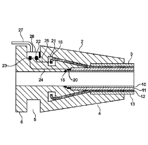
Figure 2 shows a cross section of an assembly 1 according to the present
invention. The assembly 1 comprises an end-fitting 2 and an unbonded
flexible pipe 3 which is terminated in the end-fitting 2.
The carcass layer 10 is terminated in the body 4 of the end-fitting at the
carcass ring 15. The internal pressure sheath 11 is also terminated in the
end-fitting 2 and fixed by pressure means (not shown). The tensile armour 12
is terminated in a cavity 16 in the end-fitting 2. The tensile armour 12 is
fixed
by an epoxy resin filled into the cavity 16. Finally, the outer sheath 13 is
zo terminated in the body 4 of the end-fitting. The outer sheath 13 is
fixed by
pressure means (not shown).
The carcass 10 and the tensile armour 12 are equipped with electrical
connection points 20 and 21 which are connected to the connection points 22
and 23 located in the annular channel 5 of the end-fitting 2 via the wiring 24
and 25. The connection points 20, 21 and 22, 23 and the wiring 24 and 25
are integrated in the end-fitting 2.
CA 02995257 2018-02-09
WO 2017/025096
PCT/DK2016/050262
The connection points 22 and 23 are protected by a housing 26 which fulfill
the requirements in Directive 94/9/EC - ATEX Guidelines, from the European
Community.
Via the cable 27 the connections points are connected to an external
5 electrical power source, whereby it is possible to establish an
electrical circuit
between the external electrical power source and the carcass 10 and the
tensile armour 12.
Figure shows 3 shows an embodiment in which the housing 26 protecting the
connection points 22 and 23 is located in a recess 28 in the body 4 of the
10 end-fitting 2. The cable 27 is lead through the upper part of the
housing 26
and at least partly sheltered by the channel 5 of the end-fitting 2.
Alternatively the cable 27 may be lead through holes 7 of the flange 6.
In an alternative embodiment of the invention only the carcass is connected
to the cable and the end-fitting is used as return lead. This is possible
since
the tensile armour according to this embodiment has electrical contact with
the end-fitting. However, the carcass should be carefully insulated from the
electrically conductive parts of the end-fitting.
Consequently the present invention provides an assembly of an end-fitting
and an unbonded flexible pipe in which a connector is integrated in the end-
fitting and allows electrical access from the outside directly to the carcass
of
the pipe and optionally and other electrically conductive armour layer.