Sélection de la langue

Search

Sommaire du brevet 3000976 

Énoncé de désistement de responsabilité concernant l'information provenant de tiers

Une partie des informations de ce site Web a été fournie par des sources externes. Le gouvernement du Canada n'assume aucune responsabilité concernant la précision, l'actualité ou la fiabilité des informations fournies par les sources externes. Les utilisateurs qui désirent employer cette information devraient consulter directement la source des informations. Le contenu fourni par les sources externes n'est pas assujetti aux exigences sur les langues officielles, la protection des renseignements personnels et l'accessibilité.

Disponibilité de l'Abrégé et des Revendications

L'apparition de différences dans le texte et l'image des Revendications et de l'Abrégé dépend du moment auquel le document est publié. Les textes des Revendications et de l'Abrégé sont affichés :

  • lorsque la demande peut être examinée par le public;
  • lorsque le brevet est émis (délivrance).
(12) Brevet: (11) CA 3000976
(54) Titre français: RECEPTACLE RECTANGULAIRE MOULE PAR SOUFFLAGE PERFECTIONNE
(54) Titre anglais: IMPROVED BLOW MOLDED RECTANGULAR CONTAINER
Statut: Octroyé
Données bibliographiques
(51) Classification internationale des brevets (CIB):
  • B65D 1/26 (2006.01)
  • B29C 49/04 (2006.01)
  • B65D 1/40 (2006.01)
(72) Inventeurs :
  • GILL, MATTHEW T. (Etats-Unis d'Amérique)
  • ROUBAL, EDWARD J., III (Etats-Unis d'Amérique)
  • PRITCHETT, RAYMOND A., JR. (Etats-Unis d'Amérique)
  • TAYLOR, LARRY M. (Etats-Unis d'Amérique)
  • SNYDER, JEFFREY (Etats-Unis d'Amérique)
(73) Titulaires :
  • GRAHAM PACKAGING COMPANY, L.P. (Etats-Unis d'Amérique)
(71) Demandeurs :
  • GRAHAM PACKAGING COMPANY, L.P. (Etats-Unis d'Amérique)
(74) Agent: NORTON ROSE FULBRIGHT CANADA LLP/S.E.N.C.R.L., S.R.L.
(74) Co-agent:
(45) Délivré: 2020-04-28
(22) Date de dépôt: 2011-12-29
(41) Mise à la disponibilité du public: 2012-09-13
Requête d'examen: 2018-04-10
Licence disponible: S.O.
(25) Langue des documents déposés: Anglais

Traité de coopération en matière de brevets (PCT): Non

(30) Données de priorité de la demande:
Numéro de la demande Pays / territoire Date
13/036,722 Etats-Unis d'Amérique 2011-02-28

Abrégés

Abrégé français

Un réceptacle en plastique moulé par soufflage par extrusion comprend un corps principal et une finition qui délimite une ouverture. La finition comporte une surface supérieure et une surface extérieure sur laquelle est délimité un bourrelet dencliquetage. Afin déviter laffaissement de la surface supérieure, plusieurs rainures sont délimitées dans la surface extérieure, chacune des rainures traversant le bourrelet dencliquetage. De plus, le corps principal comporte une surface extérieure qui délimite une forme sensiblement rectangulaire aux coins arrondis lorsquon lobserve en coupe transversale. La surface extérieure de la finition a également une forme sensiblement rectangulaire aux coins arrondis lorsquon lobserve en coupe transversale. La forme de la finition, lorsquon lobserve en coupe transversale, est plus petite que la forme du corps principal. Un rebord est délimité entre la surface extérieure du corps principal et la surface extérieure de la finition. Le rebord a une première largeur, adjacente à lun des angles arrondis de la finition, qui est supérieure à une seconde largeur qui nest pas adjacente à lun des angles arrondis de la finition.


Abrégé anglais

An extrusion blow molded plastic container includes a main body portion and a finish portion that defines an opening. The finish portion has an upper surface and an outer surface on which a snap bead is defined. In order to prevent saddling of the upper surface, a plurality of grooves is defined in the outer surface, each of the grooves passing through the snap bead. In addition, the main body portion has an outer surface that defines a substantially rectangular shape with rounded corners when viewed in transverse cross-section. The outer surface of the finish portion also has a substantially rectangular shape with rounded corners when viewed in transverse cross-section. The shape of the finish portion when viewed in transverse cross-section is smaller than the shape of the main body portion. A ledge is defined between the outer surface of the main body portion and the outer surface of the finish portion. The ledge has a first width, adjacent to one of the rounded corners of the finish portion, which is greater than a second width that is not adjacent to one of the rounded corners of the finish portion.

Revendications

Note : Les revendications sont présentées dans la langue officielle dans laquelle elles ont été soumises.


CLAIMS
1. An extrusion blow molded plastic container, comprising:
a main body portion, said main body portion having an outer surface defining a

substantially rectangular shape with rounded corners when viewed in transverse
cross-section;
a finish portion defining an opening, the finish portion having an upper
surface and an
outer surface that defines a substantially rectangular shape with rounded
corners when viewed in
transverse cross-section, the shape of the finish portion when viewed in
transverse cross-section
being smaller than the shape of the main body portion; and
a continuous ledge defined along an entire perimeter of the container between
the outer
surface of the main body portion and the outer surface of the finish portion,
and wherein the
ledge has a first maximum width at one of the rounded corners of the finish
portion, and a second
maximum width at a long side of the container, wherein the first maximum width
is greater than
the second maximum width, where the outer surface of the finish portion has a
snap bead defined
thereon.
2. An extrusion blow molded plastic container according to claim 1, wherein
a difference
between the first width and the second width is substantially within a range
of about 0.01 inch to
about 0.3 inch.
3. An extrusion blow molded plastic container according to claim 2, wherein
the difference
between the first width and the second width is substantially within a range
of about 0.03 inch to
about 0.2 inch.
4. An extrusion blow molded plastic container according to claim 3, wherein
the difference
between the first width and the second width is substantially within a range
of about 0.07 inch to
about 0.15 inch.
5. An extrusion blow molded plastic container according to claim 1, wherein
the outer
surface of the finish portion further has a plurality of grooves defined
therein, each of the
plurality of grooves passing through the snap bead.
6

6. An extrusion blow molded plastic container according to claim 5, wherein
each of the
plurality of grooves has a substantially vertical orientation.
7. An extrusion blow molded plastic container according to claim 5, wherein
the plurality of
grooves are defined on a long side of the finish portion, the long side having
a first width, each
of the plurality of grooves having a bottom surface that has a maximum width
when viewed in
transverse cross-section, and wherein a ratio of a sum of the maximum widths
of the plurality of
grooves to the first width is substantially within a range of about 0.1 to
about 0.4.
8. An extrusion blow molded plastic container according to claim 7, wherein
the ratio is
substantially within a range of about 0.15 to about 0.35.
9. An extrusion blow molded plastic container according to claim 8, wherein
the ratio is
substantially within a range of about 0.2 to about 0.3.
10. An extrusion blow molded plastic container, comprising:
a main body portion;
a finish portion defining an opening, the finish portion having an upper
surface and an
outer surface on which an outwardly projecting snap bead is defined about the
finish portion
wherein the finish portion when viewed in transverse cross section has a pair
of long sides and a
pair of short sides having a shorter length relative to the long sides; and
a plurality of grooves defined in the outer surface at least along one of the
long sides of
the finish portion and configured to interrupt the snap bead into a plurality
of snap bead
segments, wherein the plurality of grooves are configured to inhibit saddling
of the at least one
long side of the finish portion.
11. An extrusion blow molded plastic container according to claim 10,
wherein each of the
plurality of grooves has a substantially vertical orientation.
12. An extrusion blow molded plastic container according to claim 10,
wherein at least one
of the plurality of grooves is tapered, having a first inner width and a
second outer width that is
7

greater than the first inner width.
13. An extrusion blow molded plastic container according to claim 10,
wherein at least one
of a plurality of grooves has a bottom surface and a pair of side surfaces,
and wherein at least one
of the side surfaces is oriented at a first angle with respect to the bottom
surface when viewed in
transverse cross-section, the first angle being substantially within a range
of about 30° to
about 60°
14. An extrusion blow molded plastic container according to claim 13,
wherein the first angle
is substantially within a range of about 35 degrees to about 55 degrees.
15. An extrusion blow molded plastic container according to claim 14,
wherein the first angle
is substantially within a range of about 40 degrees to about 50 degrees.
16. An extrusion blow molded plastic container according to claim 10,
wherein no groove is
positioned on either of the short sides.
17. An extrusion blow molded plastic container according to claim 10,
wherein a first
plurality of grooves is defined in the outer surface of the finish portion on
a first of the long
sides, and a second plurality of grooves is defined in the outer surface of
the finish portion on a
second of the long sides.
18. An extrusion blow molded plastic container according to claim 17,
wherein the first
plurality of grooves comprises at least three grooves, and second plurality of
grooves comprises
at least three grooves.
19. An extrusion blow molded plastic container according to claim 10,
wherein the plurality
of grooves are defined on a long side of the finish portion, the long side
having a first width,
each of the plurality of grooves having a bottom surface that has a maximum
width when viewed
in transverse cross-section, and wherein a ratio of a sum of the maximum
widths of the plurality
of grooves to the first width is substantially within a range of about 0.1 to
about 0.4.
8

20. An extrusion blow molded plastic container according to claim 19,
wherein the ratio is
substantially within a range of about 0.15 to about 0.35.
21. An extrusion blow molded plastic container according to claim 20,
wherein the ratio is
substantially within a range of about 0.2 to about 0.3.
22. The extrusion blow molded plastic container of claim 10, wherein each
of the plurality of
grooves pass completely through the snap bead.
9

Description

Note : Les descriptions sont présentées dans la langue officielle dans laquelle elles ont été soumises.

=
WO 2012/121785 PCT/US2011/067854
IMPROVED BLOW MOLDED RECTANGULAR CONTAINER
BACKGROUND OF THE INVENTION
1. Field of the Invention
[0001] This invention relates generally to the field of blow molded plastic
containers, and
more specifically to a rectangular blow molded plastic container that has
improved resistance
to deformation such as saddling.
2. Description of the Related Techno12gy
[0002] The extrusion blow molding process involves capturing a portion of a
hot,
continuously extruded parison of plastic material in a moving mold, which may
be mounted
on a shuttle or a rotating wheel. The captured plastic material is inflated
against the interior
of the mold, forming a hollow article. Flash material is typically trimmed
from the article
after it has been ejected from the mold.
[0003] Various consumer products, such as food products, are packaged for
sale in
extrusion blow molded plastic containers that are sealed with a closure. One
type of such
container is shown in FIGURE 6. It includes a generally rectangular main body
portion and a
finish portion that has a circumferentially extending snap bead. The finish
portion has an
upper surface that defines a rim framing an opening that provides access to
the interior of the
container.
[0004] One problem that has persisted in the manufacture of containers of
the type that are
shown in FIGURE 6 is that the central portions of the upper rim tend to
develop a concave
shape, especially on the long sides of the container. This phenomenon is known
as saddling,
and it adversely affects the ability of a closure to form a good seal with the
upper surface of
the finish portion. The saddling is visible in the finite element analysis
display that is
provided in FIGURE 6.
1
CA 3000976 2018-04-10

=
WO 2012/121785 PCT/US2011/067854
[0005] A need exists for an improved blow molded rectangular plastic
container that
exhibits superior resistance to saddling during the molding process.
SUMMARY OF THE INVENTION
[0006] Accordingly, it is an object of the invention to provide an improved
blow molded
rectangular plastic container that exhibits superior resistance to saddling
during the molding
process.
[0007] In order to achieve the above and other objects of the invention, an
extrusion blow
molded plastic container according to a first aspect of the invention includes
a main body
portion and a finish portion that defines an opening. The finish portion has
an upper surface
and an outer surface on which a snap bead is defined. A plurality of grooves
is defined in the
outer surface, each of the grooves passing through the snap bead.
[0008] An extrusion blow molded plastic container according to a second
aspect of the
invention includes a main body portion that has an outer surface defining a
substantially
rectangular shape with rounded corners when viewed in transverse cross-
section. The
container further has a finish portion defining an opening. The finish portion
has an upper
surface and an outer surface that defines a substantially rectangular shape
with rounded
corners when viewed in transverse cross-section. The shape of the finish
portion when
viewed in transverse cross-section is smaller than the shape of the main body
portion. The
container further has a ledge defined between the outer surface of the main
body portion and
the outer surface of the finish portion. The ledge has a first width, adjacent
to one of the
rounded corners of the finish portion, which is greater than a second width
that is not adjacent
to one of the rounded corners of the finish portion.
[0009] These and various other advantages and features of novelty that
characterize the
invention are pointed out with particularity in the claims annexed hereto and
forming a part
hereof. However, for a better understanding of the invention, its advantages,
and the objects
obtained by its use, reference should be made to the drawings which form a
further part
hereof, and to the accompanying descriptive matter, in which there is
illustrated and described
a preferred embodiment of the invention.
2
CA 3000976 2018-04-10

=
WO 2012/121785 PCT/US2011/067854
BRIEF DESCRIPTION OF THE DRAWINGS
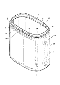
[00010] FIGURE 1 is a perspective view of a container that is constructed
according to a
preferred embodiment of the invention;
[00011] FIGURE 2 is a front elevational view of the container that is shown in
FIGURE 1;
[00012] FIGURE 3 is a top plan view of the container that is shown in FIGURE
1;
[00013] FIGURE 4 is a side elevational view of the container that is shown in
FIGURE 1;
[00014] FIGURE 5 is a cross-sectional view taken along lines 5-5 in FIGURE 4;
[00015] FIGURE 6 is a finite element analysis display depicting saddling
occurring in a
conventional rectangular blow molded container; and
[00016] FIGURE 7 is a finite element analysis display depicting the reduction
of settling
that is achieved in a container that is constructed according to the
embodiment of FIGURE 1.
DETAILED DESCRIPTION OF THE PREFERRED EMBODIMENT(S)
[00017] Referring now to the drawings, wherein like reference numerals
designate
corresponding structure throughout the views, and referring in particular to
FIGURE 1, an
extrusion blow molded rectangular plastic container 10 includes a main body
portion 12 and a
finish portion 14 defining an opening 16 that provides access to a hollow
interior of the
container 10.
[00018] The finish portion 14 has an upper surface 18 that defines a rim
framing the
opening 16. The finish portion 14 also has an outer surface 20 on which a
generally
circumferentially extending snap bead 22 is defined. The snap bead 22 projects
radially
outwardly from adjacent areas of the finish portion 14, and preferably
substantially resides
within a horizontal plane that is transverse to a longitudinal axis of the
container 10.
[00019] A plurality of grooves 24 are preferably defined in the outer surface
20 of the finish
portion 14. Each of the grooves 24 preferably passes through the snap bead 22.
Each of the
grooves 24 preferably has a substantially vertical orientation. As is best
shown in FIGURE 3,
at least one of the plurality of grooves 24 is preferably tapered, having a
first, inner width W1
3
CA 3000976 2018-04-10

WO 2012/121785 PCT/US2011/067854
and a second, outer width W2 that is greater than the inner width WI. The
inner width W1
represents the maximum transverse extent of a bottom surface 26 of the groove
24.
[00020] The groove 24 further includes a pair of side surfaces 28 that are
angled outwardly
from the bottom surface 26 when viewed in transverse cross-section at an angle
a. Angle a is
preferably substantially within a range of about 30 to about 600, more
preferably
substantially within a range of about 350 to about 55 and most preferably
substantially within
a range of about 40 to about 50 .
[00021] As FIGURE 3 best shows, finish portion 14 preferably has a first pair
of long sides
30 and a second pair of shorts sides 32. The plurality of grooves 24 is
preferably positioned
on at least one of the long sides 30, and more preferably a first plurality of
groove 24 is
provided on the first long side 30 and a second plurality of grooves 24 is
provided on the
second long side 30. The first and second pluralities of grooves 24 are
preferably symmetrical
with respect to each other. Preferably, no groove 24 is provided on either of
the short sides
32.
[00022] The first plurality of grooves preferably includes three grooves 24,
and the second
plurality of grooves also preferably includes three grooves 24.
[00023] Referring again to FIGURE 3, it will be seen that each of the long
sides 30 of the
finish portion 14 has a first width W3. Preferably, a ratio of the sum of the
maximum widths
W1 of the bottom surfaces 26 of the grooves 24 on each of the long sides 30 to
the first width
W3 is substantially within a range of about 0.1 to about 0.4, more preferably
substantially
within a range of about 0.15 to about 0.35 and most preferably substantially
within a range of
about 0.2 to about 0.3.
[00024] As FIGURE 1 shows, the main body portion 12 has an outer surface that
defines a
substantially rectangular shape with rounded corners 36 when viewed in
transverse cross-
section. The outer surface 20 of the finish portion 14 also has a generally
rectangular shape
with rounded corners 38 when viewed in transverse cross-section.
[00025] As FIGURES 4 and 5 best show, a ledge 34 is defined between an upper
end of the
outer surface of the main body portion 12 and the lower end of the outer
surface of the finish
portion 14. Ledge 34 has a first, maximum width W4 that is adjacent to one of
the rounded
4
CA 3000976 2018-04-10

= =
WO 2012/121785
PCT/US2011/067854
corners 38 of the finish portion 14, and a second minimum width W5 that is
located away
from the rounded corners 38. Second minimum width W5 in the preferred
embodiment is
located on one of the long sides 30 of the finish portion 14. The first width
W4 is preferably
less than the second width W5. Preferably, a difference between the first
width W4 and the
second width W5 is substantially within a range of about 0.01 inch to about
0.3 inch, more
preferably substantially within a range of about 0.03 inch to about 0.2 inch
and most
preferably substantially with a range of about 0.07 inch to about 0.15 inch.
[00026] FIGURE 7 is a finite element analysis display depicting the reduced
extent of
saddling that occurs turning the manufacture of a container that is
constructed according to
the embodiment of FIGURE 1.
[00027] It is to be understood, however, that even though numerous
characteristics and
advantages of the present invention have been set forth in the foregoing
description, together
with details of the structure and function of the invention, the disclosure is
illustrative only,
and changes may be made in detail, especially in matters of shape, size and
arrangement of
parts within the principles of the invention to the full extent indicated by
the broad general
meaning of the terms in which the appended claims are expressed.
CA 3000976 2018-04-10

Dessin représentatif
Une figure unique qui représente un dessin illustrant l'invention.
États administratifs

Pour une meilleure compréhension de l'état de la demande ou brevet qui figure sur cette page, la rubrique Mise en garde , et les descriptions de Brevet , États administratifs , Taxes périodiques et Historique des paiements devraient être consultées.

États administratifs

Titre Date
Date de délivrance prévu 2020-04-28
(22) Dépôt 2011-12-29
(41) Mise à la disponibilité du public 2012-09-13
Requête d'examen 2018-04-10
(45) Délivré 2020-04-28

Historique d'abandonnement

Il n'y a pas d'historique d'abandonnement

Taxes périodiques

Dernier paiement au montant de 263,14 $ a été reçu le 2023-12-15


 Montants des taxes pour le maintien en état à venir

Description Date Montant
Prochain paiement si taxe générale 2024-12-30 347,00 $
Prochain paiement si taxe applicable aux petites entités 2024-12-30 125,00 $

Avis : Si le paiement en totalité n'a pas été reçu au plus tard à la date indiquée, une taxe supplémentaire peut être imposée, soit une des taxes suivantes :

  • taxe de rétablissement ;
  • taxe pour paiement en souffrance ; ou
  • taxe additionnelle pour le renversement d'une péremption réputée.

Les taxes sur les brevets sont ajustées au 1er janvier de chaque année. Les montants ci-dessus sont les montants actuels s'ils sont reçus au plus tard le 31 décembre de l'année en cours.
Veuillez vous référer à la page web des taxes sur les brevets de l'OPIC pour voir tous les montants actuels des taxes.

Historique des paiements

Type de taxes Anniversaire Échéance Montant payé Date payée
Requête d'examen 800,00 $ 2018-04-10
Enregistrement de documents 100,00 $ 2018-04-10
Le dépôt d'une demande de brevet 400,00 $ 2018-04-10
Taxe de maintien en état - Demande - nouvelle loi 2 2013-12-30 100,00 $ 2018-04-10
Taxe de maintien en état - Demande - nouvelle loi 3 2014-12-29 100,00 $ 2018-04-10
Taxe de maintien en état - Demande - nouvelle loi 4 2015-12-29 100,00 $ 2018-04-10
Taxe de maintien en état - Demande - nouvelle loi 5 2016-12-29 200,00 $ 2018-04-10
Taxe de maintien en état - Demande - nouvelle loi 6 2017-12-29 200,00 $ 2018-04-10
Taxe de maintien en état - Demande - nouvelle loi 7 2018-12-31 200,00 $ 2018-12-07
Taxe de maintien en état - Demande - nouvelle loi 8 2019-12-30 200,00 $ 2019-12-19
Taxe finale 2020-06-08 300,00 $ 2020-03-10
Taxe de maintien en état - brevet - nouvelle loi 9 2020-12-29 200,00 $ 2020-12-15
Taxe de maintien en état - brevet - nouvelle loi 10 2021-12-29 255,00 $ 2021-12-15
Taxe de maintien en état - brevet - nouvelle loi 11 2022-12-29 254,49 $ 2022-12-15
Taxe de maintien en état - brevet - nouvelle loi 12 2023-12-29 263,14 $ 2023-12-15
Titulaires au dossier

Les titulaires actuels et antérieures au dossier sont affichés en ordre alphabétique.

Titulaires actuels au dossier
GRAHAM PACKAGING COMPANY, L.P.
Titulaires antérieures au dossier
S.O.
Les propriétaires antérieurs qui ne figurent pas dans la liste des « Propriétaires au dossier » apparaîtront dans d'autres documents au dossier.
Documents

Pour visionner les fichiers sélectionnés, entrer le code reCAPTCHA :


Pour visualiser une image, cliquer sur un lien dans la colonne description du document. Pour télécharger l'image (les images), cliquer l'une ou plusieurs cases à cocher dans la première colonne et ensuite cliquer sur le bouton "Télécharger sélection en format PDF (archive Zip)" ou le bouton "Télécharger sélection (en un fichier PDF fusionné)".

Liste des documents de brevet publiés et non publiés sur la BDBC .

Si vous avez des difficultés à accéder au contenu, veuillez communiquer avec le Centre de services à la clientèle au 1-866-997-1936, ou envoyer un courriel au Centre de service à la clientèle de l'OPIC.


Description du
Document 
Date
(yyyy-mm-dd) 
Nombre de pages   Taille de l'image (Ko) 
Revendications 2019-10-29 4 131
Dessins 2019-10-29 7 341
Taxe finale 2020-03-10 5 176
Dessins représentatifs 2020-04-08 1 11
Page couverture 2020-04-08 1 48
Abrégé 2018-04-10 1 23
Revendications 2018-04-10 3 121
Description 2018-04-10 5 207
Dessins 2018-04-10 7 385
Modification 2018-04-10 4 121
Complémentaire - Certificat de dépôt 2018-05-02 1 150
Revendications 2018-05-10 2 56
Dessins représentatifs 2018-06-18 1 10
Page couverture 2018-06-18 2 53
Modification 2018-10-19 3 92
Demande d'examen 2019-04-29 4 254
Modification 2019-10-29 8 392