Note : Les descriptions sont présentées dans la langue officielle dans laquelle elles ont été soumises.
CA 03001635 2018-04-11
WO 2017/064030 PCT/EP2016/074283
1
An ophthalmic progressive addition lens for a myopic and presbyopic
wearer; method for providing such a lens.
The invention relates generally to the field of vision improvement and
more specifically concerns an ophthalmic progressive addition lens for a
myopic
and presbyopic wearer. It also relates to a method for providing such a lens.
Conventionally, spectacles lenses are manufactured on request in
accordance with specifications intrinsic to individual wearers. Such
specifications
generally encompass a medical prescription made by an ophthalmologist or an
eye care practitioner.
A myopic wearer has a negative optical power correction for far vision.
According to the present invention, one considers that a myopic wearer has a
prescribed far vision mean refractive power which is equal or less to minus 1
Diopter. For presbyopic wearers, the value of the power correction is
different for
far vision and near vision, due to the difficulties of accommodation in near
vision.
The prescription thus comprises a far-vision power value and an addition
representing the power increment between far vision and near vision. The
addition is qualified as prescribed addition ADD.
The inventors have noticed that current ophthalmic progressive addition
lens for a myopic and presbyopic wearer can still be improved so as to enhance
the wearer's visual comfort.
A problem that the invention aims to solve is thus to enhance the wearer's
visual comfort.
For this purpose, a subject of the invention is an ophthalmic progressive
addition lens for a myopic and presbyopic wearer which has a prescribed far
vision mean refractive power equal or less to minus 1 Diopter and a non nil
prescribed addition, ADD, said lens having a mean refractive power, PPO(a,
(3),
a module of resulting astigmatism, ASR(a, (3), an acuity loss value ACU(a,
[3.),
where said (a, [3.) functions are determined in as-worn conditions of the lens
by
CA 03001635 2018-04-11
WO 2017/064030 PCT/EP2016/074283
2
the wearer, and a first acuity criterion, AcuityCriterion1 which fulfils
following
requirement:
AcuityCriterion1 1340 D2.deg2
and where, "D" refers to Diopter, "deg" to degree, AcuityCriterion1 is defined
as a
combination of PPO(a, [3.), ASR(a, [3.), ADD, and ACU(a, [3.).
According to an embodiment, AcuityCriterion1 fulfils following
requirement: AcuityCriterion1 1390 D2.deg2.
According to an embodiment, AcuityCriterion1 fulfils following
requirement: AcuityCriterion1 1440 D2.deg2.
The inventors have discovered that to defining a threshold value of an
acuity criterion is suitable to characterize ophthalmic progressive addition
lens for
a myopic and presbyopic wearer where the wearer's visual comfort is enhanced
in view of known prior art ophthalmic progressive addition lens.
According to different embodiments of the present invention, that may be
combined:
- the lens is further characterized by a meridian line, ML(a, [3.), a
fitting
cross, FC(aFc, PFc), said (a, [3.) functions being determined in as-worn
conditions of the lens by the wearer for gaze directions (a, [3.) joining the
center of rotation of the eye, CRE, and the lens, where a is a lowering
angle in degree and í3 is an azimuth angle in degree and wherein:
= the acuity loss value ACU(a, [3.) is expressed in logMAR and
defined according to following equation:
ACU(a, [3.) = - log (AC /0(a, í3)/100), where:
= AC`Yo(a, [3.) = 100 ¨ 63 x P(a, [3.) - 44.3 x ASR(a, [3.) + 7.2 x P(a,
[3)2 + 19.5 x P(a, [3.) x ASR(a, [3.) + ASR(a, [3)2 ; when P(a, [3.) o;
and
= ACcY0(a, [3.) = 100 - 44.3 x ASR(a, [3.) + ASR(a, [3)2 ; when P(a, [3.)
= P(a, [3.) = PPO(a, [3.) ¨ PPO(a, p_a_mer);
CA 03001635 2018-04-11
WO 2017/064030 PCT/EP2016/074283
3
= p_a_mer is the value of the azimuth angle (3 on the meridian line,
ML(a, (3), at the lowering angle a;
and where AcuityCriterion1 = Numerator1 / Denominator;
= Numerator1 = LAcuSub85(0.1) x LAcuAlpha85(0.1) x ADDp4;
= Denominator = AsrGradMean x PeaksMean x PVL2;
= LAcuSub85(0.1) is the angular extent (in deg2) of the zone
where ACU(a, (3) 0.1 logMAR, inside a circle, CIR,
centered
on (a, (3) = (12,0), which radius is 35 degrees, and where a
a85%, a85% being the lowering angle where 85% of the
prescribed addition is perceived by the wearer on the meridian
line;
= LAcuAlpha85(0.1) is the acuity width (in deg) at a85% between
two iso- acuity loss lines corresponding to 0.1 logMAR and is
equal to (3_,(ACU(a85 /0, (3)=0.1) - I3_(ACU(a85%, (3)=0.1), where
(3_, is greater than p_a_mer(a85 /0) and (3_ is less than
p_a_mer(a85%);
= PVL is the power variation length is expressed in deg and
defined as being equal to (a85% - a15 /0), a15 /0 being the
lowering angle where 15% of the prescribed addition is
perceived by the wearer on the meridian line;
= AsrGradMean is the mean of the norm of the gradient of
resulting astigmatism, ASR(a, (3), expressed in Diopter per
degree, calculated inside a circle, CIR, centered on (a, (3) =
(12,0), which radius is 35 degrees;
= PeaksMean is the mean maximum module of resulting
astigmatism (in Diopter,) which is equal to [ASRmax(aL, PO +
ASRmax(aRd301/2, where ASRmax(aL, PO is the maximum
module of resulting astigmatism on a side (left side) of the
meridian line, and ASRmax(aR, r3R) is the maximum module of
resulting astigmatism on the other side (right side) of the
meridian line that are both determined inside a circle, CIR,
centered on (a, (3) = (12,0), which radius is 35 degrees;
CA 03001635 2018-04-11
WO 2017/064030 PCT/EP2016/074283
4
- a second acuity criterion, AcuityCriterion2, fulfils following
requirement:
AcuityCriterion2 2900 D2.deg2, where:
= AcuityCriterion2 = Numerator2 / Denominator;
= Numerator2 = LAcuSub85(0.2) x LAcuAlpha85(0.2) x ADDp4;
= LAcuSub85(0.2) is the angular extent (in deg2) of the zone
where ACU(a, (3) 0.2 logMAR, inside a circle, CIR, centered
on (a, (3) = (12,0), which radius is 35 degrees, and where a
a85%;
= LAcuAlpha85(0.2) is the acuity width (in deg) at a85% between
two iso-acuity loss lines corresponding to 0.2 logMAR and is
equal to 13,(ACU(a85 /0, (3)=0.2) ¨ I3_(ACU(a85%, (3)=0.2),
where (3, is greater than p_a_mer(a85 /0) and (I is less than
p_a_mer(a85`)/0);
= According to an embodiment, AcuityCriterion2 fulfils following
requirement: AcuityCriterion2 3100 D2.deg2.
= According to an embodiment, AcuityCriterion2 fulfils following
requirement: AcuityCriterion2 3300 D2.deg2.
- a third acuity criterion, AcuityCriterion3, fulfils following
requirement:
AcuityCriterion3 118 D.deg, where:
= AcuityCriterion3 = Numerator3 / Denominator;
= Numerator3 = LAcuSubFC(0.1) x ADDp3;
= LAcuSubFC(0.1) is the angular extent (in deg2) of the zone
where ACU(a, (3) 0.1 logMAR, inside a circle, CIR, centered
on (a, (3) = (12,0), which radius is 35 degrees, and where a
aFc;
= According to an embodiment, AcuityCriterion3 fulfils following
requirement: AcuityCriterion3 120 D.deg.
= According to an embodiment, AcuityCriterion3 fulfils following
requirement: AcuityCriterion3 123 D.deg.
- a fourth acuity criterion, AcuityCriterion4, fulfils following
requirement:
AcuityCriterion4 185 D.deg, where:
= AcuityCriterion4 = Numerator4 / Denominator;
CA 03001635 2018-04-11
WO 2017/064030 PCT/EP2016/074283
= Numerator4 = LAcuSubFC(0.2) x ADDp3;
= LAcuSubFC(0.2) is the angular extent (in deg2) of the zone
where ACU(a, 8) 0.2 logMAR, inside a circle, CIR, centered
on (a, 8) = (12,0), which radius is 35 degrees, and where a
5 aFc;
= According to an embodiment, AcuityCriterion4 fulfils following
requirement: AcuityCriterion4 192 D.deg.
= According to an embodiment, AcuityCriterion4 fulfils following
requirement: AcuityCriterion4 200 D.deg.
- a fifth acuity criterion, AcuityCriterion5, fulfils following requirement:
AcuityCriterion5 280 D.deg, where:
= AcuityCriterion5 = Numerator5 / Denominator;
= Numerator5 = LAcuDomain(0.1) x ADDp3;
= LAcuDomain(0.1) is the angular extent (in deg2) of the zone
where ACU(a, 8) 0.1 logMAR, inside a circle, CIR, centered
on (a, 8) = (12,0), which radius is 35 degrees;
= According to an embodiment, AcuityCriterion5 fulfils following
requirement: AcuityCriterion5 289 D.deg.
= According to an embodiment, AcuityCriterion5 fulfils following
requirement: AcuityCriterion5 297 D.deg.
- a sixth acuity criterion, AcuityCriterion6, fulfils following
requirement:
AcuityCriterion6 385 D.deg, where:
= AcuityCriterion6 = Numerator6 / Denominator;
= Numerator6 = LAcuDomain(0.2) x ADDp3;
= LAcuDomain(0.2) is the angular extent (in deg2) of the zone
where ACU(a, 8) 0.2 logMAR, inside a circle, CIR, centered
on (a, 8) = (12,0), which radius is 35 degrees.
= According to an embodiment, AcuityCriterion6 fulfils following
requirement: AcuityCriterion6 397 D.deg.
= According to an embodiment, AcuityCriterion6 fulfils following
requirement: AcuityCriterion6 410 D.deg.
CA 03001635 2018-04-11
WO 2017/064030 PCT/EP2016/074283
6
In another aspect, the present invention also provides a method
implemented by computer means for providing an ophthalmic progressive
addition lens to a myopic and presbyopic wearer having a prescribed far vision
mean refractive power equal or less to minus 1 Diopter and a non nil
prescribed
addition, ADD, comprising the step of calculating a mean refractive power
repartition, PPO(a, [3.), a module of resulting astigmatism repartition,
ASR(a, [3.),
an acuity loss value repartition ACU(a, [3.), where said (a, [3.) functions
are
calculated in as-worn conditions of the lens by the wearer, so as to fulfil
following
requirement of a first acuity criterion, AcuityCriterion1:
AcuityCriterion1 1340 D2.deg2;
Where, "D" refers to Diopter, "deg" to degree, AcuityCriterion1 is defined as
a
combination of PPO(a, [3.), ASR(a, [3.), ADD, and ACU(a, [3.).
According to different embodiments of the method of the present
invention, that may be combined:
- the method further comprising following steps:
= Calculating or defining a meridian line, ML(a, [3.),
= Calculating or defining a fitting cross, FC(aFc, PFc),
= Calculating the mean refractive power, PPO(a, [3.), and the module
of resulting astigmatism, ASR(a, r3), determined in as-worn
conditions of the lens by the wearer for gaze directions (a, [3.)
joining the center of rotation of the eye, CRE, and the lens, where
a is a lowering angle in degree and í3 is an azimuth angle in
degree, an acuity loss value ACU(a, [3.) is expressed in logMAR
and defined according to following equation:
ACU(a, [3.) = - log (AC /0(a, í3)/100), where :
= AC`Yo(a, [3.) = 100 ¨ 63 x P(a, [3.) - 44.3 x ASR(a, [3.) + 7.2 x
P(a, [3)2 + 19.5 x P(a, [3.) x ASR(a, [3.) + ASR(a, [3)2 ; when
P(a, [3.) o; and
= ACcYo(a, [3.) = 100 - 44.3 x ASR(a, [3.) + ASR(a, [3)2 ; when
P(a, [3.) < o;
= P(a, [3.) = PPO(a, [3.) ¨ PPO(a, p_a_mer);
CA 03001635 2018-04-11
WO 2017/064030 PCT/EP2016/074283
7
= p_a_mer is the value of the azimuth angle í3 on the meridian
line, ML(a, [3.), at the lowering angle a;
and where AcuityCriterion1 = Numerator1 / Denominator;
= Numerator1 = LAcuSub85(0.1) x LAcuAlpha85(0.1) x
ADDp4;
= Denominator = AsrGradMean x PeaksMean x PVL2;
= LAcuSub85(0.1) is the angular extent (in deg2) of the zone
where ACU(a, [3.)
0.1 logMAR, inside a circle, CIR,
centered on (a, [3.) = (12,0), which radius is 35 degrees, and
where a a85%, a85% being the lowering angle where
85% of the prescribed addition is perceived by the wearer
on the meridian line;
= LAcuAlpha85(0.1) is the acuity width (in deg) at a85%
between two iso-acuity loss lines corresponding to 0.1
logMAR and is equal to:
(3,(ACU(a85 /0, í3)=O.1) ¨ (3_(ACU(a85 /0, p)=c).1), where [3.,
is greater than p_a_mer(a85 /0) and [3._ is less than
p_a_mer(a85%);
= PVL is the power variation length is expressed in deg and
defined as being equal to (a85% - a15 /0), a15 /0 being the
lowering angle where 15% of the prescribed addition is
perceived by the wearer on the meridian line;
= AsrGradMean is the mean of the norm of the gradient of
resulting astigmatism, ASR(a, [3.), expressed in Diopter per
degree, calculated inside a circle, CIR, centered on (a, [3.) =
(12,0), which radius is 35 degrees;
= PeaksMean is the mean maximum module of resulting
astigmatism (in Diopter) which is equal to [ASRmax(aL, PO +
ASRmax(aR, í3R)1/2, where AsRmax(aL, po is the maximum
module of resulting astigmatism on a side (left side) of the
meridian line, and ASRmax(aR, PR) is the maximum module
of resulting astigmatism on the other side (right side) of the
CA 03001635 2018-04-11
WO 2017/064030 PCT/EP2016/074283
8
meridian line that are both determined inside a circle, CIR,
centered on (a, (3) = (12,0), which radius is 35 degrees;
- one calculates the lens so as to fulfil following requirement of a second
acuity criterion, AcuityCriterion2:
AcuityCriterion2 2900 D2.deg2, where:
= AcuityCriterion2 = Numerator2 / Denominator;
= Numerator2 = LAcuSub85(0.2) x LAcuAlpha85(0.2) x ADDp4;
= LAcuSub85(0.2) is the angular extent (in deg2) of the zone where
ACU(a, (3) 0.2 logMAR, inside a circle, CIR, centered on (a, (3) =
(12,0), which radius is 35 degrees, and where a a85%;
= LAcuAlpha85(0.2) is the acuity width (in deg) at a85% between
two iso-acuity loss lines corresponding to 0.2 logMAR and is equal
to
13,(ACU(a85 /0, 13)=0.2) ¨ 13_(ACU(a85 /0, 13)=0.2), where 13, is
greater than 13_a_mer(a85 /0) and (I is less than 13_a_mer(a85 /0);
- one calculates the lens so as to fulfil following requirement of a third
acuity
criterion, AcuityCriterion3:
AcuityCriterion3 118 D.deg, where:
= AcuityCriterion3 = Numerator3 / Denominator;
= Numerator3 = LAcuSubFC(0.1) x ADDp3;
= LAcuSubFC(0.1) is the angular extent (in deg2) of the zone where
ACU(a, (3) 0.1 logMAR, inside a circle, CIR, centered on (a, (3) =
(12,0), which radius is 35 degrees, and where a aFc;
- one calculates the lens so as to fulfil following requirement of a fourth
acuity criterion, AcuityCriterion4:
AcuityCriterion4 185 D.deg, where:
= AcuityCriterion4 = Numerator4 / Denominator;
= Numerator4 = LAcuSubFC(0.2) x ADDp3;
= LAcuSubFC(0.2) is the angular extent (in deg2) of the zone
where ACU(a, (3) 0.2 logMAR, inside a circle, CIR, centered
on (a, (3) = (12,0), which radius is 35 degrees, and where a
aFc;
CA 03001635 2018-04-11
WO 2017/064030 PCT/EP2016/074283
9
- one calculates the lens so as to fulfil following requirement of a fifth
acuity
criterion, AcuityCriterion5:
AcuityCriterion5 280 D.deg, where:
= AcuityCriterion5 = Numerator5 / Denominator;
= Numerator5 = LAcuDomain(0.1) x ADDp3;
= LAcuDomain(0.1) is the angular extent (in deg2) of the zone
where ACU(a, 8) 0.1 logMAR, inside a circle, CIR, centered
on (a, 8) = (12,0), which radius is 35 degrees;
- one calculates the lens so as to fulfil following requirement of a sixth
acuity criterion, AcuityCriterion6:
AcuityCriterion6 385 D.deg, where:
= AcuityCriterion6 = Numerator6 / Denominator;
= Numerator6 = LAcuDomain(0.2) x ADDp3;
= LAcuDomain(0.2) is the angular extent (in deg2) of the zone
where ACU(a, 8) 0.2 logMAR, inside a circle, CIR, centered
on (a, 8) = (12,0), which radius is 35 degrees;
- here above requirements of preferred embodiments directed to
AcuityCriterion1 and/or AcuityCriterion2 and/or AcuityCriterion3 and/or
AcuityCriterion4 and/or AcuityCriterion5 and/or AcuityCriterion6 may be
chosen within the scope of the method of the present invention.
- the method comprises an optimization routine where at least a target is
chosen within requirement of an acuity criterion chosen in the list
consisting of AcuityCriterion1, AcuityCriterion2, AcuityCriterion3,
AcuityCriterion4, AcuityCriterion5, AcuityCriterion6.
In still another aspect, the present invention relates to a computer
program product comprising one or more stored sequence of instruction that is
accessible to a processor and which, when executed by the processor, causes
the processor to carry out at least one of the steps of the different
embodiments
of the preceding method.
The invention also relates to a computer-readable medium carrying one or
more sequences of instructions of the preceding computer program product.
CA 03001635 2018-04-11
WO 2017/064030 PCT/EP2016/074283
Description of the drawings
The features of the present invention, as well as the invention itself, both
5 as to its structure and its operation, will be best understood from the
accompanying non limiting drawings and examples, taken in conjunction with the
accompanying description, in which :
- figures 1 and 2 show, diagrammatically, optical systems of eye and
lens and ray tracing from the center of rotation of the eye ;
10 - figure 3 shows field vision zones of an ophthalmic progressive
addition
lens;
- figures 4 to 14 show diagrams helping understanding the definitions of
the
criteria used within the frame of the present invention;
- figures 15 to 18 give optical characteristics of an ophthalmic
progressive
addition lens according to the prior art;
- figures 19 to 22 give optical characteristics of an ophthalmic
progressive
addition lens according to the invention.
On the figures, following references correspond to followings:
= MER is the meridian line;
= NVGD is the near vision gaze direction;
= FVGD is the far vision gaze direction;
= FCGD is the fitting cross gaze direction
Definitions
The following definitions are provided so as to define the wordings used
within the frame of the present invention.
The wordings "wearer's prescription", also called "prescription data", are
known in the art. Prescription data refers to one or more data obtained for
the
wearer and indicating for at least an eye, preferably for each eye, a
prescribed
sphere SPHp, and/or a prescribed astigmatism value CYLp and a prescribed axis
CA 03001635 2018-04-11
WO 2017/064030 PCT/EP2016/074283
11
AXIS suitable for correcting the ametropia of each eye for the wearer and, if
suitable, a prescribed addition ADDp suitable for correcting the presbyopia of
each of his eyes.
"Progressive ophthalmic addition lenses" are known in the art. According
to the invention, the lens may be a standard lens but also a lens for
information
glasses, wherein the lens comprises means for displaying information in front
of
the eye. The lens may also be suitable for sunglasses or not. All ophthalmic
lenses of the invention may be paired so as to form a pair of lenses (left eye
LE,
right eye RE).
A "gaze direction" is identified by a couple of angle values (a,r3), wherein
said angles values are measured with regard to reference axes centered on the
center of rotation of the eye, commonly named as "CRE". More precisely, figure
1 represents a perspective view of such a system illustrating parameters a and
[3
used to define a gaze direction. Figure 2 is a view in the vertical plane
parallel to
the antero-posterior axis of the wearer's head and passing through the center
of
rotation of the eye in the case when the parameter [3 is equal to O. The
center of
rotation of the eye is labeled CRE. The axis CRE-F', shown on Figure 2 in a
dot-
dash line, is the horizontal axis passing through the center of rotation of
the eye
and extending in front of the wearer ¨ that is the axis CRE-F' corresponding
to
the primary gaze direction. The lens is placed and centered in front of the
eye
such that the axis CRE-F' cuts the front surface of the lens on a point called
the
fitting cross, which is, in general, present on lenses to enable the
positioning of
lenses in a frame by an optician. The point of intersection of the rear
surface of
the lens and the axis CRE-F' is the point, O. A vertex sphere, which center is
the
center of rotation of the eye, CRE, and has a radius q' = O-CRE, intercepts
the
rear surface of the lens in a point of the horizontal axis. A value of radius
q' of
25.5 mm corresponds to a usual value and provides satisfying results when
wearing the lenses. Other value of radius q' may be chosen. A given gaze
direction, represented by a solid line on figure 1, corresponds to a position
of the
eye in rotation around CRE and to a point J (see figure 2) of the vertex
sphere;
the angle [3 is the angle formed between the axis CRE-F' and the projection of
the straight line CRE-J on the horizontal plane comprising the axis CRE-F';
this
CA 03001635 2018-04-11
WO 2017/064030 PCT/EP2016/074283
12
angle appears on the scheme on Figure 1. The angle a is the angle formed
between the axis CRE-J and the projection of the straight line CRE-J on the
horizontal plane comprising the axis CRE-F'; this angle appears on the scheme
on Figures 1 and 2. A given gaze view thus corresponds to a point J of the
vertex
sphere or to a couple (a,6). The more the value of the lowering gaze angle is
positive, the more the gaze is lowering and the more the value is negative,
the
more the gaze is rising. In a given gaze direction, the image of a point M in
the
object space, located at a given object distance, is formed between two points
S
and T corresponding to minimum and maximum distances JS and JT, which
would be the sagittal and tangential local focal lengths. The image of a point
in
the object space at infinity is formed, at the point F'. The distance D
corresponds
to the rear frontal plane of the lens.
For each gaze direction (a,6), a mean refractive power PPO(a,6), a module of
astigmatism ASR(a,6) and an axis AXE(a,6) of this astigmatism, and a module of
resulting (also called residual or unwanted) astigmatism ASR(a,6) are defined.
"Astigmatism" refers to astigmatism generated by the lens, or to residual
astigmatism (resulting astigmatism) which corresponds to the difference
between
the prescribed astigmatism (wearer astigmatism) and the lens-generated
astigmatism; in each case, with regards to amplitude or both amplitude and
axis;
"Ergorama" is a function associating to each gaze direction the usual
distance of an object point. Typically, in far vision following the primary
gaze
direction, the object point is at infinity. In near vision, following a gaze
direction
essentially corresponding to an angle a of the order of 35 and to an angle 6
of
the order of 5 in absolute value towards the nasal side, the object distance
is of
the order of 30 to 50 cm. For more details concerning a possible definition of
an
ergorama, US patent US-A-6,318,859 may be considered. This document
describes an ergorama, its definition and its modeling method. For a method of
the invention, points may be at infinity or not. Ergorama may be a function of
the
wearer's ametropia. Using these elements, it is possible to define a wearer
optical power and astigmatism, in each gaze direction. An object point M at an
object distance given by the ergorama is considered for a gaze direction
(a,6).
An object proximity Prox0 is defined for the point M on the corresponding
light
CA 03001635 2018-04-11
WO 2017/064030 PCT/EP2016/074283
13
ray in the object space as the inverse of the distance MJ between point M and
point J of the vertex sphere:
Prox0=1/MJ
This enables to calculate the object proximity within a thin lens
approximation for
all points of the vertex sphere, which is used for the determination of the
ergorama. For a real lens, the object proximity can be considered as the
inverse
of the distance between the object point and the front surface of the lens, on
the
corresponding light ray.
For the same gaze direction (a,r3), the image of a point M having a given
object
proximity is formed between two points S and T which correspond respectively
to
minimal and maximal focal distances (which would be sagittal and tangential
focal distances). The quantity Proxl is called image proximity of the point M:
T i r i 1
Pr oxi = ¨ ¨ + ¨
2 JT JS)
By analogy with the case of a thin lens, it can therefore be defined, for a
given
gaze direction and for a given object proximity, i.e. for a point of the
object space
on the corresponding light ray, an optical power PPO as the sum of the image
proximity and the object proximity.
PPO = Prox0 + Proxl
The optical power is also called refractive power.
With the same notations, an astigmatism AST is defined for every gaze
direction
and for a given object proximity as:
1 1
AST = ¨ ¨ ¨
JT JS
This definition corresponds to the astigmatism of a ray beam created by the
lens.
The resulting astigmatism ASR is defined for every gaze direction through the
lens as the difference between the actual astigmatism value AST for this gaze
direction and the prescribed astigmatism for the same lens. The residual
astigmatism (resulting astigmatism) ASR more precisely corresponds to module
of the vectorial difference between actual (AST, AXE) and prescription data
(CYLp, AXIS).
When the characterization of the lens is of optical kind, it refers to the
ergorama-eye-lens system described above. For simplicity, the term 'lens' is
CA 03001635 2018-04-11
WO 2017/064030 PCT/EP2016/074283
14
used in the description but it has to be understood as the 'ergorama-eye-lens
system'. The values in optic terms can be expressed for gaze directions.
Conditions suitable to determine of the ergorama-eye-lens system are called in
the frame present invention "as-worn conditions".
In the remainder of the description, terms like up , bottom ,
horizontal , vertical , above , below , or other words indicating
relative position may be used. These terms are to be understood in the wearing
conditions of the lens. Notably, the "upper" part of the lens corresponds to a
negative lowering angle a <0 and the "lower" part of the lens corresponds to
a
positive lowering angle a >00
.
A "far-vision gaze direction", referred as FVGD, is defined for a lens, as
the vision gaze direction corresponding to the far vision (distant) reference
point
and thus (aFv, r3Fv), where the mean refractive power is substantially equal
to the
mean prescribed power in far vision, the mean prescribed power being equal to
SPHp-p(CYLp/2). Within the present disclosure, far-vision is also referred to
as
distant-vision.
A "near-vision gaze direction", referred as NVGD, is defined for a lens, as
the vision gaze direction corresponding to the near vision (reading) reference
point, and thus (aNv, PNO, where the refractive power is substantially equal
to the
prescribed power in far vision plus the prescribed addition, ADD.
A "fitting-cross gaze direction", referred as FCGD, is defined for a lens, as
the vision gaze direction corresponding to the fitting cross reference point
and
thus (aFc, PFc).
The "meridian line", referred as ML(a,r3), of a progressive lens is a line
defined from top to bottom of the lens and passing through the fitting cross
where one can see clearly an object point. Said meridian line is defined on
the
basis of the repartition of module of resulting astigmatism, ASR, over the (a,
(3)
domain and substantially correspond to the center of the two central iso-
module
of resulting astigmatism values which value is equal to 0.25 Diopter. To be
more
specific and according to the present invention the meridian line is
calculated
according to following method:
- One defines the gaze direction, FCGD, corresponding to the fitting
cross
CA 03001635 2018-04-11
WO 2017/064030
PCT/EP2016/074283
(aFC, PFC);
- One calculates the lowering angle a NV corresponding to the near vision
gaze direction;
- For each lowering angle a comprised between aFc and aNv, one calculates
5 the azimuth angle (3 corresponding to the midway direction between the
two central iso-module of resulting astigmatism values which value is
equal to 0.25 Diopter; said calculated directions are referred as (a,, (3);
one calculates a straight line, d2, so as to minimizes the deviation of
(a,, PO to said straight line, according to following equation:
d2 : I3(a)= a2a +b2;a < a < aNv
a2,b2 : min{E(a2a, +b2 r}
where min function relates to determining the a2 and b2 parameters so
as to minimize the equation between brackets.
- One calculates a pivot direction (ap,v, NO defined as the
intersection
between the straight line d2 and a line corresponding to (3 = r3Fc, where :
(fify, b2)
a1
ply
15 a2
1/4/17 = PFC
- One calculates a straight line, dl, where : dl: p(a), . ;a
- One determines r3Nv as being the azimuth angle (3 of straight line d2 for
aNv; where /3v = a2aNv b2 ;
- For each lowering angle a greater than aNv, one determines the azimuth
angle (3 corresponding to the midway direction between the two central
iso-module of resulting astigmatism values which value is equal to 0.25
Diopter; said calculated directions are referred as (aj, (3); one calculates a
straight line, d3, so as to minimizes the deviation of (aj, (3) to said
straight
line and that passes at the direction (aNv, r3Nv); if the calculated slope is
negative, the sloped is chosen to be nil; d3 is thus defined according to
following equation :
CA 03001635 2018-04-11
WO 2017/064030 PCT/EP2016/074283
16
d3 : I3(a) = a3 (a ¨ a Nv)+ 13 Nv; a Nv < a
a3 : min {E (a3 (aj¨a)+ 13,7-13j)2 a3 0}
- The meridian line is finally defined as being the line built when
following
the three segments dl, d2, d3.
"Micro-markings" also called "alignment reference marking" have been
made mandatory on progressive lenses by the harmonized standards ISO
13666:2012 ("Alignment reference marking: permanent markings provided by the
manufacturer to establish the horizontal alignment of the lens or lens blank,
or to
re-establish other reference points") and ISO 8990-2 ("Permanent marking: the
lens has to provide at least following permanent markings: alignment reference
markings comprising two markings distant from 34 mm one of each other,
equidistant from a vertical plane passing through the fitting cross or the
prism
reference point"). Micro-markings that are defined the same way are also
usually
made on complex surfaces, such as on a front surface of a lens with a front
surface comprising a progressive or regressive front surface.
"Temporary markings" may also be applied on at least one of the two
surfaces of the lens, indicating positions of control points (reference
points) on
the lens, such as a control point for far-vision, a control point for near-
vision, a
prism reference point and a fitting cross for instance. The prism reference
point
PRP is considered here at the midpoint of the straight segment which connects
the micro-markings. If the temporary markings are absent or have been erased,
it
is always possible for a skilled person to position the control points on the
lens
by using a mounting chart and the permanent micro-markings. Similarly, on a
semi-finished lens blank, standard ISO 10322-2 requires micro-markings to be
applied. The centre of the aspherical surface of a semi-finished lens blank
can
therefore be determined as well as a referential as described above.
Figure 3 shows field vision zones of an ophthalmic progressive addition
lens 30 where said lens comprises a far vision (distant vision) zone 32
located in
the upper part of the lens, a near vision zone 36 located in the lower part of
the
lens and an intermediate zone 34 situated between the far vision zone 32 and
the near vision zone 36. The meridian line is referred as 38.
CA 03001635 2018-04-11
WO 2017/064030 PCT/EP2016/074283
17
A plurality of criteria has been defined in the scope of the present
invention and there definitions are illustrated by figures 4 to 13.
In the background of figures 4 to 11, the acuity loss contour plot of a same
example of an ophthalmic progressive addition lens is represented.
In the background of figure 12, the module of resulting astigmatism
contour plot of the same example of an ophthalmic progressive addition lens is
represented.
In the background of figure 13, the norm of the gradient of resulting
astigmatism contour plot of the same example of an ophthalmic progressive
addition lens is represented.
The acuity loss contour shows the variations over the (a, (3) domain of the
acuity loss value ACU(a, PO ; the acuity loss value is expressed in logMAR.
The acuity loss value ACU(a, PO is defined according to following equation:
ACU(a, PO = - log (AC /0(a, 6)1100);
AC /0(a, PO is an acuity function defined as a function of both mean
refractive
power, PPO(a, PO , and module of resulting astigmatism, ASR(a, 13); where:
= one defines a mean refractive power difference function, P(a, (3), where:
P(a, (3) = PPO(a, (3) ¨ PPO(a, p_a_mer);
p_a_mer being the value of the azimuth angle 13 on the meridian line,
ML(a, (3), at the lowering angle a;
= if P(a, PO 0, AC /0(a, PO is defined according to following equation:
ACcY0(a, PO = {100 ¨ 63 x P(a, PO - 44.3 x ASR(a, (3) + 7.2 x P(a, (3)2 + 19.5
x P(a, (3) x ASR(a, PO + ASR(a, 13)2}
= if P(a, PO < 0, AC /0(a, PO is defined according to following equation:
AC /0(a, PO = 100 - 44.3 x ASR(a, PO + ASR(a, (3)2.
Bibliographical reference of such an acuity loss definition can be found in
following document: Fauquier, C., et al. "Influence of combined power error
and
astigmatism on visual acuity." Vision Science and Its Applications, OSA
Technical Digest Series. Washington, DC: Optical Society of America (1995):
151-4.
CA 03001635 2018-04-11
WO 2017/064030 PCT/EP2016/074283
18
Acuity loss values ACU(a, (3) of the example lens are plotted in the
background of figures 4 to 11 and curves indicates iso-acuity loss values
where
there is an increment of 0.1 logMAR between neighbouring curves of different
acuity loss values. On all these figures, a circle, referred as CIR, is
represented;
said circle is centered on (a, (3) = (12,0) and its radius is equal to 35
degree. Said
circle represent the angular zone within which the criteria of the invention
are
defined.
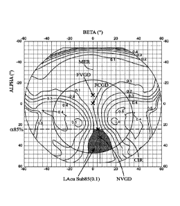
Figure 4 shows how to calculate criterion LAcuSub85(0.1);
LAcuSub85(0.1) is the angular extent (in deg2) of the zone (in grey on the
figure)
between the two central neighbouring curves of acuity loss equal to 0.1
logMAR,
said angular extent being calculated inside the circle CIR, and for lowering
angle
a more than a85% (i.e. for a a85%), where a85% is defined as the lowering
angle where 85% of the prescribed addition is perceived by the wearer on the
meridian line. The lowering angle of the meridian line where 85% of the
prescribed addition is perceived by the wearer is defined in the frame of the
present invention as being the angle lowering a where the mean refractive
power, PPO(a85 /0), fulfills following equation:
PPO(a85%) = PPO(FVGD) + 0.85 x ADD,
and where PPO(FVGD) is the mean refractive power according to the far-vision
gaze direction, FVGD.
Similar definition is used for "a lowering angle of the meridian line where
15% of the prescribed addition is perceived by the wearer" which corresponds
to
the lowering angle a where the mean refractive power, PPO(a15 /0), fulfills
following equation:
PPO(a15 /0) = PPO(FVGD) + 0.15 x ADD.
Figure 5 shows how to calculate criterion LAcuSub85(0.2);
LAcuSub85(0.2) is the angular extent (in deg2) of the zone (in grey on the
figure)
between the two central neighbouring curves of acuity loss equal to 0.2
logMAR,
said angular extent being calculated inside the circle CIR, and for lowering
angle
a more than a85% (i.e. for a a85%).
CA 03001635 2018-04-11
WO 2017/064030 PCT/EP2016/074283
19
Figure 6 shows how to calculate criterion LAcuAlpha85(0.1);
LAcuAlpha85(0.1) is the acuity width (in deg) at a85% between the two central
neighbouring curves of acuity loss equal to 0.1 logMAR; it is equal to
6+(ACU(a85 /0, 6)=0.1) ¨ 6-(ACU(a85 /o, 6)=0.1), where 6+ is greater than
p_a_mer(a85 /0) and 6- is less than p_a_mer(a85 /0).
Figure 7 shows how to calculate criterion LAcuAlpha85(0.2);
LAcuAlpha85(0.2) is the acuity width (in deg) at a85% between the two central
neighbouring curves of acuity loss equal to 0.2 logMAR; it is equal to
6+(ACU(a85 /0, 6)=0.2) ¨ 6-(ACU(a85 /o, 6)=0.2), where 6+ is greater than
p_a_mer(a85 /0) and 6- is less than p_a_mer(a85%).
Figure 8 shows how to calculate criterion LAcuSubFC(0.1);
LAcuSubFC(0.1) is the angular extent (in deg2) of the zone (in grey on the
figure)
between the two central neighbouring curves of acuity loss equal to 0.1
logMAR,
said angular extent being calculated inside the circle CIR, and for a more
than
aFc (i.e. for a aFc).
Figure 9 shows how to calculate criterion LAcuSubFC(0.2);
LAcuSubFC(0.2) is the angular extent (in deg2) of the zone (in grey on the
figure)
between the two central neighbouring curves of acuity loss equal to 0.2
logMAR,
said angular extent being calculated inside the circle CIR, and for a more
than
aFc (i.e. for a aFc).
Figure 10 shows how to calculate criterion LAcuDomain(0.1);
LAcuDomain(0.1) is the angular extent (in deg2) of the zone (in grey on the
figure) between the two central neighbouring curves of acuity loss equal to
0.1
logMAR, said angular extent being calculated inside the whole circle CIR.
Figure 11 shows how to calculate criterion LAcuDomain(0.2);
LAcuDomain(0.2) is the angular extent (in deg2) of the zone (in grey on the
figure) between the two central neighbouring curves of acuity loss equal to
0.2
logMAR, said angular extent being calculated inside the whole circle CIR.
Figure 12 shows how to calculate criterion PeaksMean; the module of
resulting astigmatism values of the example lens are plotted in the background
of
figure 12 and curves indicates iso-module of resulting astigmatism values
where
there is an increment of 0.25 Diopter between neighbouring curves of different
CA 03001635 2018-04-11
WO 2017/064030 PCT/EP2016/074283
module of resulting astigmatism values. Previously defined Circle, CIR, is
represented; PeaksMean is the mean maximum module of resulting astigmatism
(in Diopter) which is equal to [ASRmax(aL, PO + ASRmax(aR, r3R)]/2, where
ASRmax(aL, [30 is the maximum module of resulting astigmatism on a side (left
5 side) of the meridian line, and ASRmax(aR, r3R) is the maximum module of
resulting astigmatism on the other side (right side) of the meridian line that
are
both determined inside the circle, CIR.
Figure 13 shows how to calculate criterion AsrGradMean; the norm of the
gradient of resulting astigmatism values of the example lens are plotted in
the
10 background of figure 13 and curves indicates iso-norm of the gradient of
resulting astigmatism values where there is an increment of 0.05 Diopter
between neighbouring curves of different norm of the gradient of resulting
astigmatism values. AsrGradMean is defined as the mean of the norm of the
gradient of resulting astigmatism, ASR(a, (3), expressed in Diopter per
degree,
15 calculated inside the circle, CIR.
Gradient of resulting astigmatism is a vector V which components are
following:
aASR
V=
a a
V ASR
=
# afi
Its norm is given by following equation:
OVII = iiVa2 +V 2
According to an example, one determinates the gradient of resulting
astigmatism
using a finite difference method;
According to an example:
va
ASR(a + e, /3)- ASR(a - e, ,6)
..,
2e
ASR(a, 13 + e)- ASR(a, 13 - e)
V ===,
fi 2e
According to an example, E = 0.1 deg.
CA 03001635 2018-04-11
WO 2017/064030 PCT/EP2016/074283
21
Circle, referred as CI R, and centered on (a, (3) = (12,0) with a radius is
equal to
35 degree is called "Domain". AsrGradMean can be defined according to
following equation:
SumlIV(a, All; (a, Me Domain}
AsrGradMean =
Sum{1;(a, )E Domain}
Figure 14 shows the variation of object proximity Prox0 as a function of
the lowering angle a used to define the ergorama in view of US patent US-A-
6,318,859.
The ergorama used in the frame of the present invention is defined thanks to
following data, where object proximity values are given for lowering angles a:
Alpha [deg] Prox0 [D]
-50 0
-40 0
-30 0
-20 0
-10 0
0 0
10 1.65
20 2.54
2.78
2.93
2.98
25 Examples
Figures 15 to 18 give optical characteristics of an ophthalmic progressive
addition lens according to the prior art, hereafter referred as "PA_Iens".
Figures 19 to 22 give optical characteristics of an ophthalmic progressive
30 addition lens according to the invention, hereafter referred as
"INV_Iens".
CA 03001635 2018-04-11
WO 2017/064030 PCT/EP2016/074283
22
Said both ophthalmic progressive addition lenses have been designed so
as to fulfil following prescribed features:
- prescribed sphere SPHp = -4 Diopter
- prescribed astigmatism value CYLp = 0 Diopter
- prescribed axis AXIS = 00
- prescribed addition ADD= 2 Diopter
Figures 15 and 19 represent the mean refractive power repartition profile,
PPO, as a function of the lowering angle a, along the meridian line, for
respectively the prior art ophthalmic progressive addition lens and the
ophthalmic
progressive addition lens according to the present invention. Lowering angles
corresponding to a85% and to a15% are indicated.
Figures 16 and 20 represent the mean refractive power repartition, PPO,
over the (a, 6) domain, for respectively the prior art ophthalmic progressive
addition lens and the ophthalmic progressive addition lens according to the
present invention. Curves indicates iso-mean refractive power values where
there is an increment of 0.25 Diopter between neighbouring curves of different
module of resulting astigmatism values.
Figures 17 and 21 represent respectively the module of resulting
astigmatism repartition, ASR, over the (a, 6) domain, for respectively the
prior art
ophthalmic progressive addition lens and the ophthalmic progressive addition
lens according to the present invention. Curves indicates iso-module of
resulting
astigmatism values where there is an increment of 0.25 Diopter between
neighbouring curves of different module of resulting astigmatism values.
Figures 18 and 22 represent respectively the acuity loss value repartition
ACU, over the (a, 6) domain, for respectively the prior art ophthalmic
progressive
addition lens and the ophthalmic progressive addition lens according to the
present invention. Curves indicates iso-acuity loss values where there is an
increment of 0.1 logMAR between neighbouring curves of different module of
resulting astigmatism values.
Here above defined acuity criteria have been calculated for the said both
ophthalmic progressive addition lenses. Results are reported here bellow.
CA 03001635 2018-04-11
WO 2017/064030 PCT/EP2016/074283
23
Lens PA_Iens INV_Iens
AcuityCriterion1 922 1447
AcuityCriterion2 2203 3475
AcuityCriterion3 114 124
AcuityCriterion4 180 201
AcuityCriterion5 285 298
AcuityCriterion6 383 411
The inventors have done tests that demonstrate that the chosen threshold
value of AcuityCriterion1, and optionally the chosen threshold values of
AcuityCriterion2 and/or AcuityCriterion3 and/or AcuityCriterion4 and/or
AcuityCriterion5 and/or AcuityCriterion6, is (are) suitable for providing to a
myopic and presbyopic wearer an ophthalmic progressive addition lens where
the wearer's visual comfort is enhanced in view of known prior art ophthalmic
progressive addition lens.