Note : Les descriptions sont présentées dans la langue officielle dans laquelle elles ont été soumises.
1
REMOTE CONTROLLER AND METHODS FOR CONTROLLING
APPARATUS BY DIVERTING FEEDBACK SIGNAL
TECHNICAL FIELD
[0001] The systems and methods described below generally relate to the
field of remote
controllers for controlling a native feedback controller of an apparatus.
BACKGROUND
[0002] Injection molding is commonly used for manufacturing of parts made
of meltable
material, such as thermoplastic polymers. To facilitate the injection molding
of these parts, a solid
plastic resin is introduced to a heated barrel that houses a reciprocating
screw. The heated barrel
and reciprocating screw cooperate to facilitate melting of the plastic and
injecting the melted plastic
into a mold cavity for forming into a desired shape. Conventionally, an
injection molding machine
includes a controller that controls various components during the molding
process.
SUMMARY
[0003] In accordance with one embodiment, a method of manipulating a
feedback signal for
a native feedback controller of an apparatus is provided. The apparatus
further comprises a remote
controller retrofit to the native controller. The method comprises sensing a
controlled variable of an
actuation unit of the apparatus at a sensor and generating a feedback signal
by the sensor based upon
the controlled variable. At the remote controller the method further comprises
receiving the
feedback signal, generating a control signal based upon the feedback signal,
combining the control
signal and the feedback signal into a modified feedback signal, and
transmitting the modified
feedback signal to the native controller in lieu of the feedback signal. The
method further
CA 3006806 2019-10-02
CA 03006806 2018-05-29
WO 2017/105979 PCT/US2016/065496
2
comprises, at the native controller, controlling operation of the actuation
unit of the apparatus based
at least in part upon the modified feedback signal.
[0004] In accordance with another embodiment, a method of controlling a
controlled
variable of an injection molding apparatus is provided. The injection molding
apparatus comprises a
heated barrel, an injection shaft, an actuation unit, and a native controller.
The actuation unit is
operably coupled with the injection shaft and is configured to facilitate
operation of the injection
shaft with respect to the heated barrel. The method comprises sensing a
controlled variable of the
injection shaft at a sensor and generating a feedback signal by the sensor
based upon the controlled
variable. At the remote controller, the method comprises receiving the
feedback signal, comparing
the controlled variable of the injection shaft to a desired controlled
variable setpoint, generating a
control signal based upon the controlled variable and the desired controlled
variable setpoint,
combining the control signal and the feedback signal into a modified feedback
signal, and
transmitting the modified feedback signal to the native controller in lieu of
the feedback signal. At
the native controller the method further comprises controlling operation of
the actuation unit based
at least in part upon the modified feedback signal.
[0005] In accordance with another embodiment, an injection molding
apparatus comprises
an injection molding apparatus that comprises a heated barrel, an injection
shaft, an actuation unit, a
clamping unit, a nozzle, a native controller, a remote controller, and a
sensor. The injection shaft is
disposed in the heated barrel and is configured to rotate with respect to the
heated barrel. The
actuation unit is operably coupled with the injection shaft and is configured
to facilitate operation of
the injection shaft with respect to the heated barrel. The clamping unit is
for a mold. The clamping
unit is associated with the heated barrel. The nozzle is disposed at one end
of the heated barrel and
is configured to distribute contents of the heated barrel to the clamping
unit. The native controller is
CA 03006806 2018-05-29
WO 2017/105979 PCT/US2016/065496
3
in communication with the actuation unit and is configured to facilitate
operation of the injection
shaft. The remote controller is in communication with the native controller.
The sensor in
communication with the remote controller and configured to sense a controlled
variable of the
injection shaft. The remote controller is configured detect the controlled
variable from the sensor
and compare the controlled variable to a desired controlled variable setpoint.
The remote controller
is further configured to generate a control signal based upon the controlled
variable and the desired
controlled variable setpoint, combine the control signal and the feedback
signal into a modified
feedback signal, and transmit the modified feedback signal to the native
controller in lieu of the first
feedback signal. The native controller is configured to control operation of
the actuation unit based
upon the modified feedback signal.
BRIEF DESCRIPTION OF THE DRAWINGS
[0006] It is believed that certain embodiments will be better understood
from the following
description taken in conjunction with the accompanying drawings in which:
[0007] FIG. 1 is a schematic view depicting an injection molding apparatus
in accordance
with one embodiment; and
[0008] FIG. 2 is a block diagram depicting a native controller of the
injection molding
apparatus of FIG. 1 in association with a remote controller.
DETAILED DESCRIPTION
[0009] Embodiments disclosed herein generally relate to systems, machines,
products, and
methods of producing products by injection molding and, more specifically, to
systems, machines,
CA 03006806 2018-05-29
WO 2017/105979 PCT/US2016/065496
4
products, and methods of producing products by low, substantially constant
pressure injection
molding.
[0010] The term "substantially constant pressure" as used herein with
respect to a melt
pressure of a thermoplastic material, means that deviations from a baseline
melt pressure do not
produce meaningful changes in physical properties of the thermoplastic
material. For example,
"substantially constant pressure" includes, but is not limited to, pressure
variations for which
viscosity of the melted thermoplastic material does not meaningfully change.
The term
"substantially constant" in this respect includes deviations of approximately
30% from a baseline
melt pressure. For example. the term "a substantially constant pressure of
approximately 4600 psi"
includes pressure fluctuations within the range of about 6000 psi (30% above
4600 psi) to about
3200 psi (30% below 4600 psi). A melt pressure is considered substantially
constant as long as the
melt pressure fluctuates no more than 30% from the recited pressure.
[0011] In connection with the views and examples of FIGS. 1-2, wherein like
numbers
indicate the same or corresponding elements throughout the views, FIG. 1
illustrates an injection
molding apparatus 10 for producing molded plastic parts. The injection molding
apparatus 10 can
include an injection molding unit 12 that includes a hopper 14, a heated
barrel 16, a reciprocating
screw 18, and a nozzle 20. The reciprocating screw 18 can be disposed in the
heated barrel 16 and
configured to reciprocate with respect to the heated barrel 16. An actuation
unit 22 can be operably
coupled to the reciprocating screw 18 to facilitate powered reciprocation of
the reciprocating screw
18. In some embodiments, the actuation unit 22 can comprise a hydraulic motor.
In some
embodiments, the actuation unit 22 can comprise an electric motor. In other
embodiments, an
actuation unit can additionally or alternatively comprise a valve, a flow
controller, an amplifier, or
any of a variety of other suitable control devices for injection molding
apparatuses or non-injection
CA 03006806 2018-05-29
WO 2017/105979 PCT/US2016/065496
molding apparatuses. Thermoplastic pellets 24 can be placed into the hopper 14
and fed into the
heated barrel 16. Once inside the heated barrel 16, the thermoplastic pellets
24 can be heated (e.g.,
to between about 130 degrees C to about 410 degrees C) and melted to form a
molten thermoplastic
material 26. The reciprocating screw 18 can reciprocate within the heated
barrel 16 to drive the
molten thermoplastic material 26 into the nozzle 20.
[0012] The nozzle 20 can be associated with a mold 28 having first and
second mold
portions 30, 32 that cooperate to form a mold cavity 34. A clamping unit 36
can support the mold
28 and can be configured to move the first and second mold portions 30, 32
between a clamped
position (not shown) and an unclamped position (FIG. 1). When the first and
second mold portions
30, 32 are in the clamped position, molten thermoplastic material 26 from the
nozzle 20 can be
provided to a gate 38 defined by the first mold portion 30 and into the mold
cavity 34. As the mold
cavity 34 is filled, the molten thermoplastic material 26 can take the form of
the mold cavity 34.
Once the mold cavity 34 has been sufficiently filled, the reciprocating screw
18 can stop, and the
molten thermoplastic material 26 is permitted to cool within the mold 28. Once
the molten
thermoplastic material 26 has cooled and is solidified, or at least partially
solidified, the first and
second mold portions 30, 32 can be moved to their unclamped positions to allow
the molded part to
be removed from the mold 28. In some embodiments, the mold 28 can include a
plurality of mold
cavities (e.g., 34) to increase overall production rates.
[0013] The clamping unit 36 can apply a clamping force in the range of
approximately 1000
P.S.I. to approximately 6000 P.S.I. during the molding process to hold the
first and second mold
portions 30. 32 together in the clamped position. To support these clamping
forces, the mold 28, in
some embodiments, can be formed from a material having a surface hardness from
more than about
165 BHN to less than 260 BHN, although materials having surface hardness BHN
values of greater
CA 03006806 2018-05-29
WO 2017/105979 PCT/US2016/065496
6
than 260 may be used as long as the material is easily machineable, as
discussed further below. In
some embodiments, the mold 28 can be a class 101 or 102 injection mold (e.g.,
an "ultra-high
productivity mold").
[0014] The injection molding apparatus 10 can include a native controller
40 that is in signal
communication with various components of the injection molding apparatus 10.
For example, the
native controller 40 can be in signal communication with a screw control 44
via a signal line 45.
The native controller 40 can command the screw control 44 to advance the
reciprocating screw 18 at
a rate that maintains a desired molding process, such that variations in
material viscosity, mold
temperatures, melt temperatures, and other variations influencing filling
rate, are taken into account
by the native controller 40. Adjustments may be made by the native controller
40 immediately
during the molding cycle, or corrections can be made in subsequent cycles.
Furthermore, several
signals, from a number of cycles can be used as a basis for making adjustments
to the molding
process by the native controller 40.
[0015] The native controller 40 can be any of a variety of suitable
controllers for controlling
the molding process. In some embodiments, the native controller 40 can be a
PID controller. The
native controller 40 can be responsible for controlling a variety of different
functions on the
injection molding apparatus 10, such as, for example, movement of the clamping
unit 36 via a signal
line 37. The native controller 40 can be an on-board controller that is
original to the injection
molding unit 12 and built together with the injection molding unit 12. As
such, modifications to the
control architecture of the native controller 40 can be time consuming,
expensive and at times
impossible.
[0016] In one embodiment, when the actuation unit 22 is a hydraulic motor,
the screw
control 44 can comprise a hydraulic valve associated with the reciprocating
screw 18. In another
CA 03006806 2018-05-29
WO 2017/105979 PCT/US2016/065496
7
embodiment, when the actuation unit 22 is an electric motor, the screw control
44 can comprise an
electric controller associated with the reciprocating screw 18. In the
embodiment of FIG. 1, the
native controller 40 can generate a signal that is transmitted from an output
of the native controller
40 to the screw control 44.
[0017] Still referring to FIG. 1, a remote controller 46 can be in signal
communication with
the native controller 40, an injection pressure sensor 42, a melt pressure
sensor 48 located in, at, or
near, the nozzle 20, and with a cavity pressure sensor 50 located proximate an
end of the mold
cavity 34. The injection molding apparatus 10, the native controller 40 can be
in signal
communication with an injection pressure sensor 42 (shown in dashed lines)
located at the actuation
unit 22. The injection pressure sensor 42 can facilitate detection (direct or
indirect) of the injection
pressure inside of the heated barrel 16 (i.e., the pressure of the heated
barrel 16 at the beginning of
the reciprocating screw 18) by providing a feedback signal via a signal line
43 to the native
controller 40. The native controller 40 can detect the injection pressure from
the feedback signal
and can control (e.g., feedback control) the pressures within the injection
molding apparatus 10 by
controlling the screw control 44, which controls the rates of injection by the
injection molding unit
12.
[0018] The melt pressure sensor 48 can facilitate detection (direct or
indirect) of the actual
melt pressure (e.g., the measured melt pressure) of the molten thermoplastic
material 26 at or near
the nozzle 20. The melt pressure sensor 48 may or may not be in direct contact
with the molten
thermoplastic material 26. In some embodiments, the melt pressure sensor 48
can be a pressure
transducer that transmits an electrical signal via a signal line 49 to an
input of the native controller
40 in response to the melt pressure at the nozzle 20. In some embodiments, the
melt pressure sensor
48 can facilitate monitoring of any of a variety of additional or alternative
characteristics of the
CA 03006806 2018-05-29
WO 2017/105979 PCT/US2016/065496
8
molten thermoplastic material 26 at the nozzle 20 that might indicate melt
pressure, such as
temperature, viscosity, and/or flow rate, for example. If the melt pressure
sensor 48 is not located
within the nozzle 20, the native controller 40 can be set, configured, and/or
programmed with logic,
commands, and/or executable program instructions to provide appropriate
correction factors to
estimate or calculate values for the measured characteristic in, at, or near
the nozzle 20. It is to be
appreciated that sensors other than a melt pressure sensor can be employed to
measure any other
characteristics of the molten thermoplastic material 26, the screw 18, the
barrel, or the like that is
known in the art, such as, temperature, viscosity, flow rate, strain,
velocity, etc. or one or more of
any other characteristics that are indicative of any of these.
[0019] The cavity pressure sensor 50 can facilitate detection (direct or
indirect) of the melt
pressure of the molten thermoplastic material 26 in, at, or near the nozzle
20. The cavity pressure
sensor 50 may or may not be in direct contact with the molten thermoplastic
material 26. In some
embodiments, the cavity pressure sensor 50 can be a pressure transducer that
transmits an electrical
signal via a signal line 51 to an input of the native controller 40 in
response to the cavity pressure
within the mold cavity 34. In other embodiments, the cavity pressure sensor 50
can facilitate
monitoring of any of a variety of additional or alternative characteristics of
the thermoplastic
material 26 or the mold 28 that might indicate cavity pressure, such as strain
and/or flow rate of the
molten thermoplastic material 26, for example. If the cavity pressure sensor
50 is not located within
the mold cavity 34, the native controller 40 can be set, configured, and/or
programmed with logic,
commands, and/or executable program instructions to provide appropriate
correction factors to
estimate or calculate values for the measured characteristic of the mold 28.
[0020] As will be described in more detail below, the remote controller 46
can sense the
melt pressure and/or the cavity pressure of the injection molding apparatus 10
and can send a signal
CA 03006806 2018-05-29
WO 2017/105979 PCT/US2016/065496
9
(e.g., a modified feedback signal) to the native controller 40 that affects
the manner in which the
native controller 40 controls the reciprocating screw 18. The remote
controller 46 can be any of a
variety of suitable controllers for providing a modified feedback signal to
the native controller 40 to
facilitate alternative control of the molding process. In some embodiments,
the remote controller 46
can be a PID controller. In some embodiments, the remote controller 46 can be
retrofitted onto the
injection molding unit 12 to provide additional functionality not capable of
being provided by the
native controller 40.
[0021] To retrofit (e.g., associate) the remote controller 46 onto the
injection molding
apparatus 10, the outputs from the melt pressure sensor 48 and/or the cavity
pressure sensor 50 can
be disconnected from the native controller 40 and connected to the remote
controller 46 thereby
diverting their respective feedback signals to the remote controller 46. An
output from the remote
controller 46 can be connected to an input of the native controller 40 where
the melt pressure sensor
48 and/or the cavity pressure sensor 50 was previously attached. Once the
retrofit is complete, the
native controller 40 no longer directly receives feedback signals from the
melt pressure sensor 48 or
the cavity pressure sensor 50. Instead, the remote controller 46 receives
these feedback signals and
transmits a modified feedback signal to the native controller 40 that enhances
the operation of the
native controller 40, as described below. The native controller 40 and the
remote controller 46 thus
operate in a closed-loop type arrangement that existed prior to addition of
the remote controller 46.
[0022] In some embodiments, the melt pressure sensor 48 and the cavity
pressure sensor 50
can already exist on the injection molding unit 12 and can be in signal
communication with the
native controller 40. In such an embodiment, the outputs from the melt
pressure sensor 48 and the
cavity pressure sensor 50 can be disconnected from the native controller 40
and reconnected to the
remote controller 46. In some embodiments, the melt pressure sensor 48 and the
cavity pressure
CA 03006806 2018-05-29
WO 2017/105979 PCT/US2016/065496
sensor 50 might not already exist on the injection molding unit 12. In such an
embodiment, the melt
pressure sensor 48 and the cavity pressure sensor 50 can be installed during
retrofitting of the
remote controller 46 and then connected to the remote controller 46. For
purposes of this disclosure,
each of the melt pressure and the cavity pressure can be considered
"controlled variables" whereas
the injection pressure can be considered a "control variable." A controlled
variable can be
understood to be any characteristic of the thermoplastic material 26 or mold
cavity 34 that can be
controlled to facilitate effective filling of the mold cavity 34. A control
variable can be understood
to be any characteristic of the injection molding unit 12 that can be
controlled to facilitate effective
control of the reciprocating screw 18 or other injection shaft.
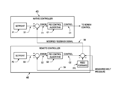
[0023] An example block diagram of the feedback relationship between the
native controller
40 and the remote controller 46 is illustrated in FIG. 2 and will now be
discussed. At the remote
controller 46, a setpoint P2 can be provided that represents a desired melt
pressure of the injection
molding apparatus 10. A signal S4 can be provided to the remote controller 46
that indicates the
actual melt pressure of the injection molding apparatus 10. The actual melt
pressure can be
compared against the setpoint P2 and an error signal E2 can be generated and
provided to a PID
control algorithm G2 that generates a control signal C2. The control signal C2
and the signal S4 can
be combined into a modified feedback signal S6. In some embodiments, the
modified feedback
signal S6 can also include a feedforward component FF1. The modified feedback
signal S6 can
additionally or alternatively include any of a variety of other suitable
control components that
facilitate generation of an effective modified feedback signal.
[0024] The modified feedback signal S6 can be transmitted to the native
controller 40 in lieu
of the feedback signal from the melt pressure sensor 48 and/or the cavity
pressure sensor 50. In one
embodiment, the modified feedback signal S6 can be transmitted over a
unidirectional transmission
CA 03006806 2018-05-29
WO 2017/105979 PCT/US2016/065496
11
link between the native controller 40 and the remote controller 46. In such an
embodiment, the
native controller 40 does not transmit any signals to the remote controller
46.
[0025] At the native controller 40, the operation of the actuation unit 22
can be controlled
according to the modified feedback signal S6. For example, a setpoint P1 can
be provided that
represents a desired injection pressure of the actuation unit 22. The setpoint
P1 can be compared
against the modified feedback signal S6 and an error signal El can be
generated. The error signal
El can be provided to a PlD control algorithm G1 that generates a control
signal Cl that commands
the screw control 44 to advance the reciprocating screw 18 at a rate that
causes the injection pressure
to converge towards the desired injection pressure indicated by the setpoint
Pl.
[0026] Although the native controller 40 is controlling to the desired
injection pressure of
the setpoint Pl, the modified feedback signal S6 from the remote controller 46
can affect the control
signal Cl from the native controller 40 in a manner that actually controls the
melt pressure of the
injection molding apparatus 10 to the desired pressure defined by the setpoint
P2 (rather than
controlling the injection pressure of the actuation unit 22 to the setpoint
P1). The remote controller
46 can thus provide the capability to control the melt pressure of the
injection molding unit 12
without requiring reprograming/reconfiguration of the control architecture of
the native controller
40. As such, the remote controller 46 can be a cost effective and
straightforward solution to add
functionality to the injection molding apparatus 10 where the native
controller 40 is not capable of
providing such functionality independently.
[0027] During a molding cycle, the melt pressure of the injection molding
unit 12 can be
changed by changing the setpoint P2. In one embodiment, different setpoints
can correspond to a
different stage of the molding cycle. For example, to initiate the initial
injecting stage, a setpoint
can be provided that causes the melt pressure to increase enough to begin
melting the thermoplastic
CA 03006806 2018-05-29
WO 2017/105979 PCT/US2016/065496
12
pellets 24 and distributing the melt to the nozzle 20. Once the melt pressure
has increased enough to
begin filling the mold cavity 34, a setpoint can be provided that initiates
the filling stage at a
pressure that is appropriate to properly fill the mold cavity 34. Once the
mold cavity 34 is almost
filled (e.g., end of fill), a setpoint can be provided to decrease enough to
initiate the packing stage
and hold at a substantially constant melt pressure during the holding stage.
[0028] The native controller 40 and/or the remote controller 46 can be
implemented in
hardware, software or any combination of both and can have any control
arrangement having one or
more controllers for accomplishing control. It is to be appreciated that,
although the native
controller 40 is described as sensing and controlling the injection pressure
of the actuation unit 22, a
native controller 40 can be configured to sense and control any of a variety
of suitable alternative
control variables, such as, for example, a temperature of the heated barrel
16, a volume of the
hopper 14, or velocity of the reciprocating screw 18. It is also to be
appreciated that, although the
remote controller 46 is described as providing the capability to control the
melt pressure of the
injection molding unit 12, a remote controller using the injection pressure of
the actuation unit 22
can be configured to sense and control any of a variety of suitable
alternative control variables, such
as, for example, cavity pressure.
[0029] The foregoing description of embodiments and examples has been
presented for
purposes of illustration and description. It is not intended to be exhaustive
or limiting to the forms
described. For, example, although the remote controller 46 is described as
being provided on an
injection molding apparatus, a remote controller can be provided on any
apparatus that employs
feedback control from a native controller to add functionality to the
apparatus where the native
controller is not capable of providing such functionality independently.
Numerous modifications are
possible in light of the above teachings. Some of those modifications have
been discussed and
13
others will be understood by those skilled in the an. The embodiments were
chosen and described
for illustration of various embodiments. The scope is, of course, not limited
to the examples or
embodiments set forth herein, but can be employed in any number of
applications and equivalent
devices by those of ordinary skill in the art. Rather it is hereby intended
the scope be defined by the
claims appended hereto. Also, for any methods claimed and/or described,
regardless of whether the
method is described in conjunction with a flow diagram, it should be
understood that unless
otherwise specified or required by context, any explicit or implicit ordering
of steps performed in
the execution of a method does not imply that those steps must be performed in
the order presented
and may be performed in a different order or in parallel.
[0030] The dimensions and values disclosed herein are not to be understood as
being strictly limited
to the exact numerical values recited. Instead, unless otherwise specified,
each such dimension is
intended to mean both the recited value and a functionally equivalent range
surrounding that value.
For example, a dimension disclosed as "40 mm" is intended to mean "about 40
mm."
[0031]
The citation of any document is not an admission that it is prior art with
respect
to any invention disclosed or claimed herein or that it alone, or in any
combination with any other
reference or references, teaches, suggests or discloses any such invention.
Further, to the extent that
any meaning or definition of a term in this document conflicts with any
meaning or definition of the
same term in a document referenced herein, the
meaning or definition assigned to that term
in this document shall govern.
CA 3006806 2019-10-02
CA 03006806 2018-05-29
WO 2017/105979 PCT/US2016/065496
14
[0032] While particular embodiments of the present invention have been
illustrated and described, it
would be obvious to those skilled in the art that various other changes and
modifications can be
made without departing from the spirit and scope of the invention. It is
therefore intended to cover
in the appended claims all such changes and modifications that are within the
scope of this
invention.