Sélection de la langue

Search

Sommaire du brevet 3010949 

Énoncé de désistement de responsabilité concernant l'information provenant de tiers

Une partie des informations de ce site Web a été fournie par des sources externes. Le gouvernement du Canada n'assume aucune responsabilité concernant la précision, l'actualité ou la fiabilité des informations fournies par les sources externes. Les utilisateurs qui désirent employer cette information devraient consulter directement la source des informations. Le contenu fourni par les sources externes n'est pas assujetti aux exigences sur les langues officielles, la protection des renseignements personnels et l'accessibilité.

Disponibilité de l'Abrégé et des Revendications

L'apparition de différences dans le texte et l'image des Revendications et de l'Abrégé dépend du moment auquel le document est publié. Les textes des Revendications et de l'Abrégé sont affichés :

  • lorsque la demande peut être examinée par le public;
  • lorsque le brevet est émis (délivrance).
(12) Brevet: (11) CA 3010949
(54) Titre français: ENSEMBLE CHASSIS DE RETENUE DE L`EMBOITURE
(54) Titre anglais: SOCKET HOLDING FRAME ASSEMBLY
Statut: Octroyé
Données bibliographiques
Abrégés

Abrégé français

Un assemblage de cadre de retenue dune douille comprend une base de piste (10), de multiples bases de retenue (20) et de multiples attaches (30). La base de piste (10) comprend un panneau inférieur (11), un canal de piste (14) et une partie de raccord (16). Le canal de piste (14) est défini dans le panneau inférieur (11). La partie de raccord (16) est formée dans le panneau inférieur (11). Les bases de retenue (20) sont installées de manière coulissante et rotative dans le canal de piste (14). Chaque base de retenue (20) comprend un trou de raccord (26) défini dans un fond de la base de retenue (10). Les attaches (30) sont installées à travers la partie de raccord (16) du panneau inférieur (11), à partir dune surface inférieure du panneau inférieur (11), et sont vissées respectivement dans les trous de raccord (26) dans les bases de retenue (20).


Abrégé anglais

A socket holding frame assembly has a track base (10), multiple holding bases (20), and multiple fasteners (30). The track base (10) has a bottom panel (11), a track channel (14), and a connection portion (16). The track channel (14) is defined in the bottom panel (11). The connection portion (16) is formed through the bottom panel (11). The holding bases (20) are mounted slidably and rotatably in the track channel (14). Each holding base (20) has a connection hole (26) defined in a bottom of the holding base (10). The fasteners (30) are mounted through the connection portion (16) in the bottom panel (11) from a bottom surface of the bottom panel (11) and are screwed respectively into the connection holes (26) in the holding bases (20).

Revendications

Note : Les revendications sont présentées dans la langue officielle dans laquelle elles ont été soumises.


8
WHAT IS CLAIMED IS:
1. A socket holding frame assembly comprising:
a track base having
a bottom panel;
a track channel defined in the bottom panel; and
a connection portion formed through the bottom panel;
multiple holding bases mounted slidably and rotatably in the track
channel in the track base, and each holding base having a respective
connection
hole defined in a bottom of the holding base; and
multiple fasteners mounted through the connection portion in the bottom
panel from a bottom surface of the bottom panel and screwed respectively into
the connection holes in the holding bases.
2. The socket holding frame assembly as claimed in claim 1, wherein the
track base has two side panels connected with two sides of the bottom panel
and
an H-shaped cross section; and
the track channel is defined between the bottom panel and the side
panels.
3. The socket holding frame assembly as claimed in claim 2, wherein
each holding base has
a bottom base mounted slidably and rotatably in the track channel in the
track base; and
a holding portion formed on and protruding from a top surface of the
bottom base.
4. The socket holding frame assembly as claimed in claim 3, wherein the

9
bottom base of each holding base is a circular board.
5. The socket holding frame assembly as claimed in claim 3, wherein the
bottom base of each holding base is a polygonal board and has two abutment
surfaces abutting two sides of the track channel.
6. The socket holding frame assembly as claimed in any one of claims 1
to 5, wherein the connection portion in the track base is an elongated through

hole.
7. The socket holding frame assembly as claimed in claim 6, wherein
each fastener is a self-tapping screw and the connection hole of each holding
base is a blind hole.
8. The socket holding frame assembly as claimed in any one of claims 1
to 5, wherein the connection portion in the track base is composed of multiple

circular through holes arranged in a line.
9. The socket holding frame assembly as claimed in claim 8, wherein
each fastener is a self-tapping screw and the connection hole of each holding
base is a blind hole.

Description

Note : Les descriptions sont présentées dans la langue officielle dans laquelle elles ont été soumises.

SOCKET HOLDING FRAME ASSEMBLY
1. Field of the Invention
The present invention relates to a socket holding frame assembly, and
more particularly to a socket holding frame assembly that can hold a position
and
a direction of a socket securely.
2. Description of Related Art
With reference to Fig. 15, a conventional socket holding frame
substantially comprises a holding base 60. Multiple holding holes 62 in
different
diameters are formed in a top surface of the holding base 60, such that
sockets
can be inserted and held in the holding holes 62.
However, the conventional socket holding frame can only hold sockets
having specific diameters, and the positions of the sockets cannot be changed
or
adjusted. Therefore, the conventional socket holding frame is not versatile
and
convenient in use.
With reference to Fig. 16, another conventional socket holding frame is
shown and substantially comprises a track base 70 and multiple holding bases
72.
The track base 70 is elongated and has a track 702 formed on and protruding
from a top surface of the track base 70. The holding bases 72 are mounted
slidably around and on the track 702 of the track base 70. Accordingly,
sockets
can be held on the holding bases 72, and the positions of the sockets on the
track
base 70 are adjustable.
However, the holding bases 72 of the conventional socket holding frame
are not rotatable relative to the track base 70. Therefore, after a socket is
held on
one of the holding bases 72, the direction of the socket is fixed and is not
CA 3010949 2018-07-10

2
rotatable and adjustable. Thus, to check the dimension mark on the socket is
inconvenient. In addition, the holding bases 72 cannot be held securely on the

track base 70, so the holding bases 72 are easily moved unintentionally
relative
to the track base 70 when an external force is applied to the socket holding
frame.
With reference to Fig. 17, further another conventional socket holding
frame is shown and substantially comprises a track base 80 and multiple
holding
bases 82. The track base 80 is elongated and has a track channel 802 defined
in a
top surface of the track base 80, the holding bases 82 are mounted slidably
and
rotatably in the track channel 802 in the track base 80. Sockets are mounted
on
the holding bases 82, and the positions and directions of the sockets can be
adjusted by moving or rotating the holding bases 82 relative to the track base
80.
However, the holding bases 82 can be held at predetermined positons
and directions firmly, so the sockets on the holding bases 82 are easily moved
or
rotated unintentionally when an external force is applied to the socket
holding
frame. Therefore, the conventional socket holding frame is not convenient in
use.
To overcome the shortcomings, the present invention tends to provide a
socket holding frame assembly to mitigate or obviate the aforementioned
problems.
The main objective of the invention is to provide a socket holding frame
assembly that can hold sockets at fixed positions and in fixed directions
securely.
The socket holding frame assembly has a track base, multiple holding
bases, and multiple fasteners. The track base has a bottom panel, a track
channel,
CA 3010949 2018-07-10

3
and a connection portion. The track channel is defined in the bottom panel.
The
connection portion is formed through the bottom panel. The holding bases are
mounted slidably and rotatably in the track channel in the track base. Each
holding base has a connection hole defined in a bottom of the holding base.
The
fasteners are mounted through the connection portion in the bottom panel from
a
bottom surface of the bottom panel and are screwed respectively into the
connection holes in the holding bases.
Other objects, advantages and novel features of the invention will
become more apparent from the following detailed description when taken in
conjunction with the accompanying drawings.
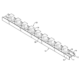
Fig. 1 is a perspective view of a first embodiment of a socket holding
frame assembly in accordance with the present invention;
Fig. 2 is an enlarged exploded perspective view of the socket holding
frame assembly in Fig. 1;
Fig. 3 is an enlarged side view in partial section of the socket holding
frame assembly in Fig. 1;
Fig. 4 is an enlarged end view in partial section of the socket holding
frame assembly in Fig. 1;
Fig. 5 is an operational perspective view of the socket holding frame
assembly in Fig. 1;
Fig. 6 is an enlarged operational exploded perspective view of the socket
holding frame assembly in Fig. 1;
Fig. 7 is an enlarged operational perspective view of the socket holding
frame assembly in Fig. 1;
CA 3010949 2018-07-10

4
Fig.8 shows operational perspective views of the socket holding frame
assembly in Fig. 1;
Fig. 9 is an exploded perspective view of a second embodiment of a
socket holding frame assembly in accordance with the present invention;
Fig. 10 is a side view in partial section of the socket holding frame
assembly in Fig. 9;
Fig. 11 is an exploded perspective view of a third embodiment of a
socket holding frame assembly in accordance with the present invention;
Fig. 12 shows operational side views in partial section of the socket
holding frame assembly in Fig. 11;
Fig. 13 is a cross sectional top view of the socket holding frame
assembly in Fig. 11;
Fig. 14 shows operational perspective views of the socket holding frame
assembly in Fig. 11;
Fig. 15 is a perspective view of a conventional socket holding frame;
Fig. 16 is a perspective view of another conventional socket holding
frame; and
Fig. 17 is a perspective view of further another conventional socket
holding frame.
With reference to Figs. 1 to 4, a socket holding frame assembly in
accordance with the present invention comprises a track base 10, multiple
holding bases 20, and multiple fasteners 30.
The track base 10 is elongated, has an H-shaped cross section, and
comprises a bottom panel 11 and two side panels 12. The side panels 12 are
CA 3010949 2018-07-10

5
connected respectively with two sides of the bottom panel 11 to define a track

channel 14 in the bottom panel 11 and between the bottom panel 11 and the side

panels 12. The bottom panel 11 has a connection portion 16 formed through the
bottom panel 11. In the first embodiment, the connection portion 16 is an
elongated through hole.
The holding bases 20 are mounted slidably and rotatably in the track
channel 14 in the track base 10 and comprise a bottom base 22 and a holding
portion 24. The bottom base 22 may be a circular board and is mounted slidably

and rotatably in the track channel 14 in the track base 10. The holding
portion 24
is formed on and protrudes from a top surface of the bottom base 22 and is
adapted to connect with a socket. Accordingly, sockets can be put on the track

base 10 via the holding bases 20. In addition, each holding base 20 has a
respective connection hole 26 defined in a bottom of the holding base 20.
The fasteners 30 are mounted through the connection portion 16 in the
bottom panel 11 from a bottom surface of the bottom panel 11 and are screwed
into the connection holes 26 in the holding bases 20 respectively.
Accordingly,
the holding bases 20 can be held in position securely by the fasteners 30. In
the
first embodiment, each fastener 30 is a self-tapping screw, and the connection

holes 26 in the holding bases 20 are blind holes. In an alternative
embodiment,
each fastener 30 is a bolt, and the connection holes 26 in the holding bases
20 are
threaded holes.
In use, with reference to Figs. 5 to 8, the holding bases 20 are put into the
track channel 14 from an end of the track base 10, and sockets 50 are
respectively put onto the holding portions 24 of the holding bases 20. The
CA 3010949 2018-07-10

6
sockets 50 are rotated to make the dimension marks on the sockets 50 face a
same direction. The fasteners 30 are then inserted through the connection
portion
16 in the bottom panel 11 from the bottom surface of the bottom panel 11 and
are
screwed respectively into the connection holes 26 in the holding bases 20.
Accordingly, the holding bases 20 with the sockets 50 can be held securely at
desired positions and in desired directions. Thus, a user can clearly
recognize the
dimensions of the sockets 50 and takes the sockets 50 for use conveniently.
Because the holding bases 20 are securely held on the track base 10 by
the fasteners 30, the positions and directions of the holding bases 20 will
not be
changed unintentionally even when an external force is applied to the socket
holding frame assembly. Therefore, the use of the socket holding frame
assembly
is stable and convenient. To change the positions or directions of the holding

bases 20 and the sockets 50, the fasteners 30 are released and the holding
bases
can be moved or rotated relative to the track channel 14 in the track base 10.
15 After the holding bases 20 are moved to desired positions or directions,
the
fasteners 30 are screwed into the connection holes 26 in the holding bases 20.

Consequently, the positons and directions of the sockets 50 can be
conveniently
adjusted.
In practice, multiple sockets 50 having different sizes are mounted on
20 the holding portions 24 of the holding bases 20 and are arranged along
the track
base 10 by size. Accordingly, the sockets 50 can be well classified on the
track
base 10 and are easily taken for use.
With reference to Figs. 9 and 10, in the second embodiment, the
connection portion 16A on the track base 10A is composed of multiple circular
CA 3010949 2018-07-10

7
through holes arranged in a line. Accordingly, when one holding base 20 is
moved to align with one of the through holes, the fastener 30 is inserted
through
the through hole and is screwed into the connection hole 26 in the holding
base
20 to hold the holding base 20 in position. After the fastener 30 is released,
the
position and direction of the holding base 20 can also be adjusted.
With reference to Figs. 11 to 14, in the third embodiment, the bottom
base 22A of each holding base 20A is a polygonal board and has two abutment
surfaces 222. When the bottom bases 22A of the holding bases 20A are mounted
in the track channel 14 in the track base 10, the abutment surfaces 222 of
each
holding base 20A can abut two opposite sides of the track channel 14 and
preferably abut the side panels 12. With such an arrangement, the holding
bases
20A are sill rotatable relative to the track base 10 and can be kept from
being
rotated while the fastener 30 is screwed into the connection hole 26A in the
holding base 20A. Therefore, to lock or to release the holding bases 20A is
convenient.
CA 3010949 2018-07-10

Dessin représentatif
Une figure unique qui représente un dessin illustrant l'invention.
États administratifs

Pour une meilleure compréhension de l'état de la demande ou brevet qui figure sur cette page, la rubrique Mise en garde , et les descriptions de Brevet , États administratifs , Taxes périodiques et Historique des paiements devraient être consultées.

États administratifs

Titre Date
Date de délivrance prévu 2020-08-18
(22) Dépôt 2018-07-10
Requête d'examen 2019-04-04
(41) Mise à la disponibilité du public 2020-01-10
(45) Délivré 2020-08-18

Historique d'abandonnement

Il n'y a pas d'historique d'abandonnement

Taxes périodiques

Dernier paiement au montant de 100,00 $ a été reçu le 2024-06-12


 Montants des taxes pour le maintien en état à venir

Description Date Montant
Prochain paiement si taxe générale 2025-07-10 277,00 $ si reçu en 2024
289,19 $ si reçu en 2025
Prochain paiement si taxe applicable aux petites entités 2025-07-10 100,00 $

Avis : Si le paiement en totalité n'a pas été reçu au plus tard à la date indiquée, une taxe supplémentaire peut être imposée, soit une des taxes suivantes :

  • taxe de rétablissement ;
  • taxe pour paiement en souffrance ; ou
  • taxe additionnelle pour le renversement d'une péremption réputée.

Les taxes sur les brevets sont ajustées au 1er janvier de chaque année. Les montants ci-dessus sont les montants actuels s'ils sont reçus au plus tard le 31 décembre de l'année en cours.
Veuillez vous référer à la page web des taxes sur les brevets de l'OPIC pour voir tous les montants actuels des taxes.

Historique des paiements

Type de taxes Anniversaire Échéance Montant payé Date payée
Le dépôt d'une demande de brevet 200,00 $ 2018-07-10
Requête d'examen 400,00 $ 2019-04-04
Taxe de maintien en état - Demande - nouvelle loi 2 2020-07-10 50,00 $ 2020-06-11
Taxe finale 2020-09-29 150,00 $ 2020-06-12
Taxe de maintien en état - brevet - nouvelle loi 3 2021-07-12 50,00 $ 2021-05-17
Taxe de maintien en état - brevet - nouvelle loi 4 2022-07-11 50,00 $ 2022-05-05
Taxe de maintien en état - brevet - nouvelle loi 5 2023-07-10 100,00 $ 2023-06-12
Taxe de maintien en état - brevet - nouvelle loi 6 2024-07-10 100,00 $ 2024-06-12
Titulaires au dossier

Les titulaires actuels et antérieures au dossier sont affichés en ordre alphabétique.

Titulaires actuels au dossier
KAO, JUI-CHIEN
Titulaires antérieures au dossier
S.O.
Les propriétaires antérieurs qui ne figurent pas dans la liste des « Propriétaires au dossier » apparaîtront dans d'autres documents au dossier.
Documents

Pour visionner les fichiers sélectionnés, entrer le code reCAPTCHA :


Pour visualiser une image, cliquer sur un lien dans la colonne description du document. Pour télécharger l'image (les images), cliquer l'une ou plusieurs cases à cocher dans la première colonne et ensuite cliquer sur le bouton "Télécharger sélection en format PDF (archive Zip)" ou le bouton "Télécharger sélection (en un fichier PDF fusionné)".

Liste des documents de brevet publiés et non publiés sur la BDBC .

Si vous avez des difficultés à accéder au contenu, veuillez communiquer avec le Centre de services à la clientèle au 1-866-997-1936, ou envoyer un courriel au Centre de service à la clientèle de l'OPIC.


Description du
Document 
Date
(yyyy-mm-dd) 
Nombre de pages   Taille de l'image (Ko) 
Dessins représentatifs 2019-12-18 1 14
Page couverture 2019-12-20 2 46
Taxe finale 2020-06-12 4 85
Dessins représentatifs 2020-07-28 1 12
Page couverture 2020-07-28 1 39
Abrégé 2018-07-10 1 18
Description 2018-07-10 7 238
Revendications 2018-07-10 2 49
Dessins 2018-07-10 17 331
Requête d'examen 2019-04-04 2 53
Lettre du bureau 2024-03-28 2 189