Note : Les descriptions sont présentées dans la langue officielle dans laquelle elles ont été soumises.
- 1 -
PRODUCT DETECTOR
Field
The current invention belongs to the domain of product conveying in an
industrial
processing line. The object of the present invention is a product detector.
Background
In the field of the present invention, products, like bottles or cans, are
conveyed
thanks to endless belt conveyors on which they stand. Conveyors have two
opposed lateral
vertical side walls between which products are moved. The speed of these
conveyors is
adjusted for controlling the overall line process and it is therefore
necessary to detect the
presence or absence of products in a predefined fixed area. The result of such
detection is
then used as an input data for controlling the movement of the conveyors.
For example, DE102010000596 discloses a product detector. Such a metallic
detector is mounted aside the conveyor, thanks to a base, fixed to the
conveyor support.
The detector has a pendulum, freely rotating around an axis parallel to the
conveying
direction. A longitudinal bar is mounted at the end of this pendulum, for
contacting the
products.
When products are absent, the longitudinal bar extends above the conveying
surface. When products are present, they push the pendulum back behind the
vertical wall
of the conveyor, by acting on the longitudinal bar. The position of the
pendulum is
detected by a metal sensing means. Therefore, the longitudinal bar is to go
through the
vertical side frontier of the conveyor.
In a normal production state, the longitudinal metallic bar is constantly
touching the
product flow. This creates problems for sensitive products, for example cans,
metallic
bottles, or any other kind of products with no later surface treatment like
labelling: the
metallic longitudinal bar scratches the surface, can collect dusts and
particles, later
transferred to the products. Therefore, there is a need in the industry for a
product detector
creating no harm on the surface of the detected products.
Also, as the longitudinal bar has to go through the vertical side frontier of
the
conveyor, merely adding a soft protection around the longitudinal bar does not
fit, because
the required opening in this frontier would then be too big and allow
circulation of
undesirable particles like broken glass, etc.
Some contactless detectors have also been proposed, for detecting metallic
cans or
products. However, such detectors are not compatible with glass products,
which cannot be
detected with the same electromagnetic principle.
Date Recue/Date Received 2022-04-28
- 2 -
Summary
Therefore, the invention aims at improving the state of the art as described
here above, by
proposing a product detector, compatible for both metallic and non metallic
products, creating no
harm on the external surface of the product, and/or compatible with small
apertures in conveyors
lateral walls. In order to reach this, the invention proposes a detector with
contact means having
the shape of a flat piece with a gentle contact surface, preferably plastic
based.
According to the invention, there is provided a detector for detecting a
product flow on a
conveyor, comprising a base, to be fixed at a side of said conveyor, a
pendulum, fixed to the based
with a rotation to an axis, said pendulum rotating when products are pushed
against it, a sensor,
for detecting the position of the pendulum. This detector is characterized in
that the pendulum
comprises at an end thereof a contact means having a flat plate shape, with a
non metallic surface
for contacting the products.
Hence, according to a broad aspect, there is provided a detector for detecting
a flow of
products on a conveyor, comprising: a base to be mounted at a side of the
conveyor, a pendulum
mounted to the base with a rotation to an axis parallel to a conveying
direction of the conveyor,
and a sensor for detecting a position of the pendulum, wherein the pendulum
rotates upon pressure
by the products against the pendulum, wherein the pendulum comprises a contact
means at an end
of the pendulum and a support structure, wherein the contact means has a flat
plate shape with a
nonmetallic surface for contacting the products, wherein an outer surface of
the contact means is
made of an elongated plastic part mounted at an end of the support structure,
wherein the elongated
plastic part has a flat plate shape and a cavity for receiving the end of the
support structure, and
wherein the cavity and the end of the support structure have complementary
elongated rectangular
shapes extending parallel to the axis.
Brief description of the drawings
Further features and advantages of the present invention will be better
understood from the
description of preferred embodiments, which is given below by way of a non-
limiting illustration,
with reference to the accompanying drawings, in which:
- figures 1 to 8 show a specific design of a plastic part, to be mounted at
the end of the
pendulum;
- figures 9 to 10 show a specific design of the end of the pendulum;
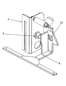
- figure 11 is a view of a product detector according to the invention;
- figure 12 is a bottom view of the same product detector;
- figure 13 focuses on the added plastic part, creating the contact means;
- figure 14 shows the detector without this plastic part;
- figure 15 schematically shows a conveyor side wall and a contact means go
through it.
Date recue/Date received 2023-05-29
- 3 -
Detailed description of embodiments
Variants, examples, and preferred embodiments of the invention are described
hereinbelow. A first object of the present invention is a detector 1 for
detecting a product
flow on a conveyor 2, comprising a base 3, to be fixed at a side of said
conveyor 2, a
pendulum 4, fixed to the based 3 with a rotation to an axis 5, said pendulum 4
rotating
when products are pushed against it, a sensor 6, for detecting the position of
the pendulum
4.
The conveyor 2 is of a closed belt principle and the base 3 of the detector 1
is
attached to a fixed infrastructure of the conveyor 2, on which the belt moves.
The detector
1 works to detect the presence or absence of products in a certain fixed area.
In order to do
this, the detector 1 has a pendulum 4 rotating to an axis 5. The pendulum 4
mainly extends
under this axis 5. Products push this pendulum 4 and displace it from its
normal stable and
balanced position. When no products are brought by the conveyor 2 in the
detection zone,
the position of the pendulum 4 is defined by its own weight, which creates a
torque to this
axis 5. The position of the pendulum 4 is therefore defined by, on the one
side, the
products themselves urged against the pendulum 4, and, on the other side, the
weight of the
pendulum 4. It should be noted that a force generating means like a spring can
be
envisaged to balance the product pressure.
The position of the pendulum 4 compared to the base 3 is detected by a sensor
6,
preferably mounted on the base 3 itself. It is preferably based on a metal
detection
principle, and a signal is triggered when metal is detected by the sensor 6,
which
corresponds to a certain position of the pendulum 4: either retracted due to
products, or
protruding onto the conveying surface due to the absence of products.
The pendulum 4 is fixed to the base 3 outside of the product conveying
surface, at
its top end, at the level of the axis 5. The axis 5 is normally parallel to
the conveying
direction of the conveyor 2.
According to the invention, the pendulum 4 comprises at an end thereof a
contact
means 7 having a flat plate shape, with a non metallic surface for contacting
the products,
so that the detector 1 can be mounted on a conveyor 2 with a side window 8 of
a reduced
height. This non metallic surface is preferably made with plastic.
In fact, the bottom end of the pendulum 4 is to contact the products.
Therefore, the
pendulum 4 has a contact means 7 at said bottom
Date Recue/Date Received 2022-04-28
CA 03014507 2018-08-14
WO 2017/141066
PCT/II32016/000157
- 4 -
end. It has a longitudinal edge, extending in the direction of the conveyor 2,
so that a transversal force from the product flow is transformed in a
pendulum 4 rotation. This contact means 7 preferably also has oblique
opposed end portions, extending from the longitudinal edge, as best seen in
the attached drawings. The contact means 7 presents such an oblique
portion at both ends to avoid products being trapped between the
longitudinal edge and the side wall 13 of the conveyor 2, or being not
detected, in both direction of flow: normal flow from upstream to
downstream, and opposite possible return flow from downstream to
upstream, in case of accumulation situations, for example.
In the prior art, this contact means 7 is based on a bent stem,
fixed at the bottom end of the pendulum 4. The invention differs from this
prior art in that the contact means 7 has the shape of a flat and thin piece
of
plastic. The use of a gentle plastic material avoids scratches on the
products, as well as noises. The outer surface of the contact means 7 is
made of such a soft material. Also, the design as a flat plate provides both a
good rigidity and a limited vertical dimensions: as will be described below
in further detail, the contact means 7 is to cross the side wall 13 of the
conveyor 2, and it is important to avoid corresponding passage apertures or
window 8 of a high vertical dimension in said side wall 13.
This design leads to gentle contact with the product, good
stiffness of the pendulum 4 and limited corresponding windows 8 in the
side wall 13.
According to a possible additional feature, the pendulum 4
comprises a support structure 9 and, mounted at an end of said support
structure 9, an elongated plastic part 10 for forming the contact means 7.
Said plastic part 10 is for example made of Ultra High Molecular Weight
Polyethylene. The support structure 9 may be made of metal, in order to be
easily detected by a sensor 6.
The overall shape of the plastic part 10 is a flat piece of plastic,
extending in a direction which is parallel to the axis 5 once installed, with
tapered sides leading to opposed end points. This plastic part 10 forms at
least the outer surface of the contact means 7, i.e. the surface which will
contact the products. The plastic part 10 preferably also forms the top
surface of the contact means 7, as best seen from figure 11, for example.
In some embodiments, the pendulum 4 forms a single piece
with a support structure 9 integral with the plastic part 10. In some
CA 03014507 2018-08-14
WO 2017/141066
PCT/II32016/000157
- 5 -
embodiments, the support structure 9 and the plastic part 10 are two
different components.
According to another possible additional feature, the plastic
part 10 and/or the support structure 9 and/or the pendulum 4 are/is obtained
by additive manufacturing, also named 3D printing. As an alternative to
injection molding, which could also be envisaged, the plastic part 10 can
therefore be obtained by such an additive manufacturing process. The
plastic part 10 is then assembled to the support structure 9. Said support
structure 9 can also be obtained by such manufacturing processes. The
whole pendulum 4 can also form one single piece, obtained with additive
manufacturing.
According to another possible feature, the plastic part 10 has a
cavity 11 for receiving the corresponding end of the support structure 9.
This cavity 11 is for cooperating with the support structure 9 on which the
plastic part 10 is mounted. In some specific embodiments, the cavity 11 and
the corresponding end of the support structure 9 have complementary
elongated shapes, preferably an overall elongated rectangle shape.
As best seen from figure 14, the support structure 9 has a
bottom end of a rectangular longitudinal shape, extending parallel to the
axis 5. Angled portions can be implemented to link this longitudinal
rectangle to the central arm of the support structure 9. The pendulum 4 is so
designed that the support structure 9 and the plastic part 10 have
complementary and cooperating geometries: the cavity 11 at the bottom of
the plastic part 10 corresponds to and fits the end of the support structure
9,
especially the longitudinal rectangle. The end of the support structure 9 fits
the cavity 11, which contributes to a good positioning.
The plastic part 10 may be fixed to the support structure 9 in a
detachable way. In other embodiments, the plastic part 10 cannot be
detached from the support structure 9, for example when overmoulding,
gluing, welding, or even a locked snap fitting is used.
Therefore, in some preferred embodiments, the plastic part 10
is detachably mounted on the support structure 9. The plastic part 10 can
then be changed if necessary, for example adapted to the products treated,
removed once weared, dirty, or broken, etc.
In some possible embodiments, the plastic part 10 is screw
mounted to the end of the support structure 9. This can be seen for example
CA 03014507 2018-08-14
WO 2017/141066
PCT/1B2016/000157
- 6 -
in figures 11 to 14. Snap fitting is also a possible embodiment of a
removable fixation of the plastic part 10 on the support structure 9.
Also, in some possible embodiments, the support structure 9
has openings 12 contributing to the balance of the pendulum 4 for it to be
urged against the products. As already explained, at least the weight of the
pendulum brings its contact means 7 above the conveying surface of the
conveyor 2. Therefore, this weight is to be adjusted in order to guarantee a
proper return of the contact means 7 in this configuration, but also to avoid
an excessive urging of the pendulum 4 on the products or a too fast return
movement, which would then tend to shock the products.
The design of the support structure 9 has openings 12,
preferably at the level of the arm between the contact means 7 and the
rotation axis 5.
In the embodiment shown in the attached drawings, the detector
1 is to be fixed at the lateral side of a conveyor 2, at its fixed
infrastructure.
Products are standing on the top surface of this conveyor 2, and moved by
it. The conveyor 2 has a side wall 13 for defining a frontier for the flow of
products. The conveyor 2 is normally of a closed loop design, and has a
fixed infrastructure on which a motor is mounted for driving said belt.
The detector 1 has a base 3 for it to be fixed to the
infrastructure of the conveyor 2. The detector 1 also has a pendulum 4,
freely rotating around an axis 5. This axis 5 is normally parallel to the
direction of the conveyor 2.
Figure 11 shows that the base 3 has an axle or shaft, extending
in a cantilever fashion in a horizontal direction. The pendulum 4 comprises
a complementary hollow tube portion, or sleeve, to be mounted on said
axle. A sensor 6 is also mounted in the base 3 and detects a tab of the
pendulum 4, see figure 11.
It is to be understood that the rotation axis 5 is located in the
top zone of the pendulum 4, so that the pendulum 4 can tilt to said axis 5
with its gravity center being under said axis 5. At the opposite bottom end,
the pendulum 4 has a contact means 7, for touching the products 2
conveyed by the conveyor 2. This contact means 7 is at the end of the
pendulum 4 and carries the surface on which products act.
When products 2 are onto the conveyor 2, they act on the
pendulum 4 and have it rotating around its axis 5 to reach a retracted
CA 03014507 2018-08-14
WO 2017/141066
PCT/1B2016/000157
-7-.
position. This means that the end portion of the contact means 7 is pushed
by the products to arrive approximately flush to the side wall 13. The
pendulum 4 is in a retracted position. When products are absent or at least
far from said side wall 13, the pendulum 4 has a different angular position
to the axis 5 and the contact means 7 slightly extends after the side wall 13,
as best seen from figure 15. The pendulum 4 is normally urged against the
products due to its own weight.
Therefore, the contact means 7 is to cross the frontier defined
by the side wall 13. As best seen from figure 15, the side wall 13 has a
window 8 through which the contact means 7 can pass. The window 8 has a
size corresponding to the size of the contact means 7 and is therefore of a
reduced vertical height, extending in a horizontal direction parallel to the
conveyor 2 plane.
In order to avoid damages on the surfaces of the products, the
contact means 7 has an outer surface made of plastic. Preferably, as seen for
example on figure 11, the contact means 7 has, from a top view, a basic
rectangular shape, reducing to two points at opposed ends thereof. The
resulting oblique contour avoids creating an abutment for the
downstreaming or upstreaming product flow.
The contact means 7 has the overall form of a blade, that is to
say a portion with a reduced height compared to its base surface. This blade
can therefore move through a small window 8 in the side wall 13.
Products come in contact with the contact means 7 at the level
of a portion of its perimeter. The contact means 7 is made of plastic at least
in this portion.
Preferably, the pendulum 4 has a plastic part 10 at the end
thereof, for forming the contact means 7. The plastic part 10 extends
essentially parallel to the axis 5, and forms the contact means 7.
The plastic part 10 is of a reduced height and extends as a flat
piece. The plastic part 10 is mounted on a support structure 9 of the
pendulum 4, as best seen on figure 2. This support structure 9 can be
metallic, for ease of detection by an electromagnetic sensor 6. This support
structure 9 ends with a longitudinal rectangular shape. The plastic part 10
surrounds this rectangular shape, at least partly. As seen on figure 2, the
bottom of the rectangular end of the support structure 9 can be free and
uncovered by the plastic part 10. At least the plastic part 10 is between the
rectangular end of the support structure 9 and the products. The plastic part
CA 03014507 2018-08-14
WO 2017/141066
PCT/1B2016/000157
-8-
preferably also completely covers the top of the end of the support
structure 9.
Preferably, the end of the support structure 9 and the plastic
part 10 have complementary shapes: the plastic part 10 has a bottom cavity
11 in which the end of the support structure 9 can be received. The cavity
11 and the corresponding portion of the support structure 9 have
complementary geometries, so that the plastic part 10 can have a stable
position once fixed to the support structure 9. This geometry comprises a
rectangle.
The pendulum 4 therefore is made of two different materials:
the support structure 9 is made of metal, and the plastic part 10 is made of
rigid but soft plastic. The edge of the contact means 7 is therefore gentle
and does not harm the surface of the product. Also, as already said, the
blade shape, having a limited height, also allows the window 8 to be of a
limited height. A reduced window 8 avoids circulation of dangerous
particles, small products, or even fallen down products.
The plastic part 10 is preferably made with ultra high molecular
weight polyethylene, for its soft contact properties.
In some possible embodiments, the pendulum 4 is formed of a
single piece, the plastic part 10 being integral with the support structure 9.
The whole pendulum 4 is then made with a gentle material like plastic for
avoiding harming the product surface for example by scratching.
In some specific embodiments, the plastic part 10 differs from
the support structure 9, and is fixed to said support. The plastic part 10 can
be definitely fixed, for example by overmoulding, gluing, locked snap
fitting, etc. The plastic part 10 can also be removably fixed to the support
structure 9 for example by screw mounting it, or by snap fitting it, etc.
Figure 1 shows a plastic part 10 fixed to the support structure 9 with four
screws.
A detachable plastic part 10 makes it possible to change the
plastic part 10 in case of excessive wear, for example.
As best seen in figure 4, the support structure 9 has a bent
lever: the support structure 9 is mounted to the base 3 at an end of said
lever, and the contact means 7 is located at the other end. The weight of this
lever contributes to bringing the contact means 7 onto the conveying
surface, for detecting the presence of products. The lever has openings 12
sized to adjust the weight of the pendulum 4.
CA 03014507 2018-08-14
WO 2017/141066
PCT/1132016/000157
- 9 -
While specific embodiments of the invention have been
described in detail, it will be appreciated by those skilled in the art that
various modifications and alternatives to those details, in addition to those
discussed above, could be developed in light of the overall teachings of the
disclosure. Accordingly, the particular arrangements disclosed are meant to
be illustrative only, and not limiting as to the scope of the invention which
is to be given the full breadth of the claims appended in any and all
equivalents thereof, including any combination of their features.