Note : Les descriptions sont présentées dans la langue officielle dans laquelle elles ont été soumises.
CARGO TRANSPORTATION SYSTEM INCLUDING A SANDWICH
PANEL AND A CHANNEL
BACKGROUND
[0001] The present application relates generally to cargo systems and
more
particularly to a cargo transportation system including a sandwich panel and a
channel.
[0002] It has long been desired in the box trailer industry to have
walls and
floors made of lightweight and strong panels which are strongly joined
together. Most
conventional trailer walls and floors, however, require a foam filling, which
is heavy and
prevents recycling, thereby increasing trailer weight which wastes fuel and/or
lessens
cargo carrying capacity. Furthermore, traditional tracks, posts and joints are
heavy,
complicated and labor intensive to install. Many also protrude within the
cargo space
and are prone to snagging by cargo when inserted in the trailer. Exemplary
conventional attempts at such a construction are disclosed in the following
United
States patents and patent publication: 7,100,971 entitled "Cargo Body with
Recessed
Posts" which issued to Pines on September 5, 2006; 8,016,152 entitled
"Container
Sidewall Connector" which issued to Roush et al. on September 13, 2011; and
2013/0224419 entitled "Composite Panel and Joint Construction" which published
to
Lee et al. on August 29, 2013.
[0003] It is noteworthy, however, that these conventional approaches
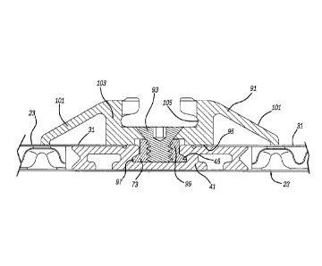
still
suffer the same snagging concerns and the panel-to-panel attachments are
expensive
to manufacture. Furthermore, most traditional devices require additional add-
on
attachment brackets which span between the adjacent panels; but these
configurations
typically require juggling of many loose parts, such as rivets, while
attempting to align
1
CA 3028083 2019-07-16
and hold the panels in position, along with undesired extra part handling and
weight.
The localized attachment points also undesirably concentrate the forces during
use
thereby creating premature panel fractures at the localized points. Moreover,
prior
panel-to-panel seams and rivet holes sometimes allow water entry such as in
rainy
weather which can harm the cargo transported in the container.
[0004] The prior riveting attachment of logistics tracks directly to
side wall
panels undesirably requires piercing of the panels and does not allow track
locational
adjustment. The end use customers or dealerships, however, often need to
subsequently move the logistics tracks which requires aftermarket hole
piercing for new
rivets and either empty leaking, unused holes or caulking of the now unused
holes,
which is time consuming and unsightly.
[0005] Commonly owned U.S. Patent Publication No. 2017/0327310,
entitled
"Cargo Container Apparatus Including a Sandwich Structure and a Track,"
discloses a
C-shaped track mounted within a depression of a sandwich structure. While it
is a
significant improvement in the industry, there is room for additional
improvements.
SUMMARY
[0006] In accordance with the present invention, a cargo
transportation
system includes a sandwich panel and a channel. In another aspect, a cargo-
securing
or logistics track, or tie-down slat, is attached to a continuously slotted
channel which is
secured within a sandwich panel of a cargo container, which employs at least
one core
sheet including alternating peaks and valleys therein in addition to attached
interior and
exterior face sheets. A further aspect employs a threaded fastener having an
enlarged
2
CA 3028083 2019-07-16
exterior face sheets. A further aspect employs a threaded fastener having an
enlarged
head, which is slidable within the slot which has an undercut or generally T-
cross
sectional shape. Yet another aspect of a cargo transportation system includes
an
interior face sheet flange of a sandwich panel, overlapping a flush mounted
lateral
segment of a slotted channel. A method of making a cargo transportation
system,
including a sandwich panel and a channel, is also provided.
[0007] The
present cargo transportation system is advantageous over prior
constructions. For example, the present cargo transportation system allows for
fast and
easy logistics track-to-side wall or floor panel adjustment with slidably
adjustable
fasteners, and without rivets or hole piercing, especially in an aftermarket
situation.
Thus, water leaks are avoided. Furthermore, the present system is
advantageously
lightweight, extremely strong and has a thin interior-to-exterior cross-
section. The
present apparatus provides an essentially flush mounted track thereby making
it easier
to load and unload cargo in the trailer or container without snags while
enhancing the
aesthetic appearance. Furthermore, fasteners can be slid to infinite positions
along the
panel-attached channel, rather than in discreet spaced apart holes, in some
embodiments, thereby making container assembly easier and stronger while
allowing
the sandwich and channel system to be manufactured and pre-assembled in an
initial
manufacturing site different than a final container assembly site and well
before the
container, trailer or vehicle is shipped to a dealer or end-use customer.
Additional
advantages and features of the present invention can be ascertained from the
following
description and appended claims, as well as in the accompanying drawings.
3
CA 3028083 2018-12-19
BRIEF DESCRIPTION OF THE FIGURES
[0008] Figure 1 is a fragmentary perspective view showing a cargo
transportation system of the present invention in a trailer;
[0009] Figure 2 is a side elevational view showing the present system;
[0010] Figure 3 is a top elevational view showing the present system;
[0011] Figure 4 is a cross-sectional view, taken within circle 4 of
Figure 3,
showing the present system;
[0012] Figure 5 is a perspective view showing the present system;
[0013] Figure 6 is a cross-sectional view, similar to Figure 4 but with
a
channel removed, showing the present system;
[0014] Figure 7 is a cross-sectional view, taken within circle 7 of
Figure 3,
showing the present system;
[0015] Figure 8 is a perspective view, taken within circle 8 of Figure
2,
showing the present system;
[0016] Figure 9 is a side elevational view, taken within circle 9 of
Figure 2,
showing the present system;
[0017] Figure 10 is a top elevational view showing the present system;
[0018] Figure 11 is a cross-sectional view, taken within circle 11 of
Figure 10,
showing the present system;
[0019] Figure 12 is a side elevational view showing another embodiment
of
the present system;
[0020] Figure 13 is a perspective view showing the Figure 12 embodiment
of
the present system;
4
CA 3028083 2018-12-19
[0021] Figure 14 is a cross-sectional view, taken along line 14 ¨ 14 of
Figure
13, showing the Figure 12 embodiment of the present system;
[0022] Figure 15 is a fragmentary and enlarged true elevational viewof a
core
employed in the present system;
[0023] Figure 16 is an exploded perspective view showing the Figure 4
embodiment of the present system;
[0024] Figure 17 is a partially exploded and fragmentary perspective
view
showing an alternate embodiment spacer employed in the present system;
[0025] Figure 18 is a partially exploded and fragmentary perspective
view
showing another alternate embodiment spacer employed in the present system;
and
[0026] Figure 19 is a fragmentary perspective view showing the present
system in a passenger vehicle.
DETAILED DESCRIPTION
[0027] Figures 1 and 2 illustrate a cargo transportation system
including a
cargo-carrying container 21, preferably a wheeled box trailer pulled by an
automotive
tractor or truck, which includes multiple sandwich panels 23 therein. Sandwich
panels
23 serve as structural side wall panels 25, which include elongated channels
41 therein,
to which structural cargo securing or logistics tracks 27, and/or tie-down
slats or rubrails
29, are attached. Sandwich panels 23 can alternately be used as a front wall,
roof or
movable door. Moreover, sandwich panels 23 may define a load bearing floor
structure.
Unless otherwise specified hereinafter, all of the trailer container
constructions
disclosed herein are also suitable for defining sections of other
transportation containers
CA 3028083 2018-12-19
such as an intermodal shipping container, a railroad car, cargo holding
portions of a
utility van or passenger vehicle, decks of a watercraft such as a cargo
carrying ship, and
the like. An exemplary intermodal shipping container is disclosed in U.S.
Patent No.
5,678,715 entitled "Composite Stacking Frame Assembly for Shipping Container"
which
issued to Sjostedt et al. on October 21, 1997.
[0028] Sandwich panels 23 can be observed in greater detail in Figures
6, 7,
15 and 16. Each sandwich panels 23 includes a first generally flat, interior
face sheet
31, a middle core sheet 33 and an opposite generally flat, exterior face sheet
35.
Furthermore, core sheet 33 includes alternating peaks 37 and valleys 39, the
external
surface of each being defined by a generally flat land 41. Moreover, raised
ridges 43
bridge or span between adjacent peaks 37 along a first width direction W but
not in the
perpendicular length direction L, where a more abrupt and steeply angled
depression 45
is formed. Depressed areas 45 are located between adjacent peaks 37 along
second
direction L although each depressed area is elongated parallel to ridges 43
since the
depressed areas are created on the back side of the ridges when the core sheet
is
formed into the desired contours from an initially flat workpiece sheet. Each
ridge 43 is
slightly lower than the generally flat lands 41 of the neighboring peaks 37.
[0029] Face sheets 31 and 35 are preferably metallic, such as low
carbon
steel, and core sheet 33 is preferably metallic such as aluminum. But any or
all of these
sheets may alternately be aluminum, low carbon steel, stainless steel or other
metallic
materials. Alternately, the face sheets can be composite materials to allow
for larger
widths than are typically available in metal sheets. The metal grain structure
is also
different in the roll/feeding direction L of core sheet 33 than in the cross-
roll/cross-
6
CA 3028083 2019-07-16
feeding direction W. The core is preferably formed by embossing rollers as is
disclosed
in commonly owned U.S. Patent Publication No. 2017/0036415 entitled "Sandwich
Structure Including Grooved Outer Sheet," U.S. Patent Publication No.
2015/0165724
entitled "Sandwich Structure," and U.S. Patent Publication No. 2015/0044494
entitled
"Optional Sandwich Core Structures and Forming Tools for the Mass Production
of
Sandwich Structures,".
[0030] The placement of ridges 43 and depressed areas 45 between the
alternating peaks and valleys of core sheet 33 give the core sheet
asymmetrical
properties or characteristics after and during forming. For example, a length
shrinkage
factor fs, which is the initial core sheet length versus the formed end sheet
length, is at
least 1.08, and more preferably at least 1.10 in the roll direction L, as
compared to a
shrinkage factor fs of approximately 1.0 in the cross-roll/cross-feeding
direction W.
Furthermore, an out-of-plane shear stiffness of core sheet 33 is at least 1.3
times
greater, and more preferably at least 1.4 times greater in the cross-
roll/cross-feeding
direction W, as compared to the roll/feeding direction L:
EL]¨ GwT/GLT 1.3
Additionally, an out-of-plane shear strength of core sheet 33 is at least 1.05
times
greater, and more preferably at least 1.1 times greater in the cross-
roll/cross-feeding
direction W, as compared to the roll/feeding direction L:
[L] ¨ TWTITLT1.05
7
CA 3028083 2019-07-16
In other words, the formed core sheet 33 can be torqued or flexed about an
axis
parallel to direction W considerably easily than in the perpendicular
direction about an
axis parallel to direction L due to the ridge and depression orientation and
positioning. It
should be appreciated that the core sheet thickness will vary after it is
embossed. This
asymmetrical core formation is very different than the symmetry desired in
various prior
constructions.
[0031] The compressive strength of the present sandwich panel 23 is
maximized where the outer sheets are bonded to the core sheet, across the
cross-
sectional thickness (as viewed in Figures 6 and 7). The relative density of
this particular
sandwich core layer can be calculated as followed:
= fs.tc
where tc is the initial sheet thickness of the core layer, C denotes the core
layer height
and fs is the shrinkage factor in the length direction L. Thus, the
asymmetrical nature of
the periodic array of peak and valley cells or dimples, as connected in one
direction by
raised ridges and separated in the other by steep depressed areas,
advantageously
provides for different directional forming and final product properties and
characteristics.
It is preferred that the open space between the sheets, including versions
with multiple
core sheets, not define a honeycomb pattern, since such a pattern exhibits
differing
performance and manufacturing characteristics. Adhesive is the sole fastener
between
the lands 37 of core sheet 33 and the adjacent inner surfaces of sheets 31 and
35 in the
presently preferred construction, although brazing may be alternately
employed.
[0032] Reference should now be made to Figures 2 ¨ 5. Elongated channel
41 includes a central and elongated, substantially T-cross sectionally shaped
slot 43
8
CA 3028083 2018-12-19
including undercut sections 45 thereof. Channel 41 also includes laterally
extending
segments 47 on either side of slot 43 which each have a hollow and generally T-
cross
sectionally shaped area 49 therein which is open toward exterior face sheet
35. Lateral
edges of each segment 47 have a depression 51 therein. Hollow areas 49 and
depressions 51 reduce weight and material costs of channel 41 while allowing
the
channel to have the same thickness as the adjacent bordering core sheets 33.
Furthermore, at least one groove or recess 53 is disposed along each generally
flat
interiorly facing surface of channel 41 to receive adhesive which bonds these
otherwise
flat surfaces of channel 41 to inner surfaces 55 and 57 of interior and
exterior face
sheets 31 and 35, respectively.
[0033] Channel 41 is preferably extruded from aluminum 6061 T6 material,
but may alternately be steel or a reinforced polymeric or composite material.
Channel
41 and its slot 43 continuously extend at least a majority, and preferably the
entire
distance between opposite peripheral edges of the associated sandwich panel
made
from face sheets 31 and 35. A flange 61 of each interior face sheet 31 extends
beyond
an internal peripheral edge 63 of core sheet 33. Moreover, an open
intermediate
portion 65 of exterior face sheet 35 projects past peripheral edge 63 of core
sheet 33. A
second core sheet 33 is also positioned upon the same exterior face sheet 35
with a
mirrored image interior face sheet 31 secured thereupon but with a gap 67
between
parallel distal edges 69 facing each other from flanges 61.
[0034] When channel 41 is inserted within the sandwich panel, as shown
in
Figure 4, flanges 61 overlap and generally hide the lateral segments 47 of
channel 41.
This allows for sufficient mating surface area therebetween to adhesively bond
channel
9
CA 3028083 2018-12-19
41 to both the inner surfaces of the two adjacent face sheets 31 and 35
without the
need for hole piercing and fasteners such as rivets or screws. In this
condition, channel
41 is generally flush or below flush of an interior plane defined by the
innermost surface
of interior face sheets 31.
[0035] As can be observed in Figure 5, a pair of oversized holes 71 are
located in outer locations along slot 43. This allows an internally threaded
nut fastener
73 to either be inserted through oversized openings 71 (especially in an
aftermarket
situation) or in an open end of slot 43 if accessible. Thereafter, nut 73 may
be
adjustably slid to infinite positions between the ends of channel 41.
[0036] As can be seen in Figures 2 and 8 ¨ 11, a cargo-contacting or
retaining
track member 91 is removeably secured to nut 73 by way of an externally
threaded, flat
head screw fastener 93. Tightening of screw fastener 93 to nut 73 will cause a
backside 95 of track 91 to bottom out against interior face sheets 31 and
exposed
surfaces of channel 41 due to a slight space between the facing surfaces of
nut 73 and
track 91. Nut 73 further includes a laterally enlarged flange 97 projecting
from a body
99. This flange engages within undercut 45 of slot 43 to allow nut adjustment
therein
prior to being cinched down by screw fastener 93.
[0037] This type of track 91 includes oppositely tapering wings 101
extending
from a main structure 103 including a continuously elongated pathway 105
therealong.
Shoring beams, supplemental decks, divider boards, straps and cargo nets may
be
removeably attached within the pathway 105 of track 91 via locking lugs, hooks
or bolt
heads. Track 91 can be vertically mounted to the vertically elongated channel
41 when
CA 3028083 2018-12-19
the panel is a container side wall, or track 91 may be horizontally mounted
between
multiple channels 41.
[0038] Figures 2 and 12 ¨ 14 illustrate another embodiment employing an
alternately configured channel 111 and a differently styled logistics track
113. Channel
111 has a generally H-cross sectional shape but is otherwise essentially the
same as in
the prior embodiment. A metallic spacer 115 is positioned between interior
face sheets
31 and the backside of track 113 and has multiple hexagonally shaped openings
117 to
engage and deter rotation of nut 73 disposed therein. Spacer 115 also serves
to space
apart two or more nuts 117 a predetermined distance away from each other
during their
adjustment along slot 43 of channel 41 to correspond to the required distance
for holes
119 and screw fasteners 93 needed to secure track 113 to nut 73.
[0039] This track configuration employs multiple central apertures 121
of a
generally I-true view shape, with bent over central tabs 123 to receive cargo
strap
hooks, lugs or the like. Track 113 is preferably horizontally mounted to
extend in a fore-
and-aft manner along sidewall panels or floor panels of the cargo carrier.
Moreover,
this configuration of spacer 115 preferable general has an I-true view shape
as can be
observed in Figure 13.
[0040] An alternate spacer 131 is illustrated in Figure 17. This employs
an
extruded metallic part having a generally flat interior facing surface 133
with an
elongated central foot 135 projecting therefrom in a generally perpendicular
manner.
Foot includes laterally extending flanges 137 which snap-fit engage with the
undercut of
the channel slot for positional retention while adjustably moving therealong.
Circular
11
CA 3028083 2018-12-19
holes 139 are spaced apart in spacer 131 to receive the bodies of nuts 73.
Optionally,
adhesive may adhere the nuts to the holes to deter rotation thereof during
fastening.
[0041] Yet another embodiment of a spacer 141 is shown in Figure 18.
This
spacer 141 is a stamped sheet metal part with predominantly flat upper and
lower
surfaces 143 and 145, respectively. However, stamped and bent fingers 147
inwardly
extend from generally polygonal shaped holes 149 which serve to contact
against and
prevent rotation of a matching generally polygonal body 99 of the nuts 73
received
therein. The fingers may optionally apply a gentle spring force against the
channel to
temporarily maintain a desired nut position during track installation.
[0042] Figure 19 shows the present tracks 41 and fasteners employed in a
sport utility vehicle, a station wagon or other such passenger carrying
wheeled,
automotive vehicle. Sandwich panel 25, including the face sheets and core
sheet, to
which the tracks 41 are inserted. It serves as a cargo-carrying floor behind a
rear
passenger seat 151.
[0043] It is alternately envisioned that a lock nut, leaf spring or
other biasing
member may be located between the nut and an adjacent surface of the slot.
This
would serve to temporarily maintain a desired location of a nut fastener when
a track is
being attached thereto. This biasing member may also be adapted to deter
rotation of
the nut within the slot. Furthermore, it is envisioned that a custom designed
nut
fastener, such as one stamped from sheet steel, has a rectangular or other
shape with
opposed flats, employed within the slot to deter rotation while allowing
linear sliding
adjustment.
12
CA 3028083 2018-12-19
[0044] The manufacturing process will now be discussed. The channel is
preferably extruded from metallic material. Thereafter, it is cut to the
desired lengths.
Masking tape is then applied on top of the slot such that adhesive is then
roll coated
onto the exterior surface of the channel. Alternately, a mask can be avoided
if adhesive
beads, swirls or the like are applied by robotically moving a nozzle relative
to a
stationary channel or moving the channel past a fixed nozzle. Next, the
exterior flat
surface of the channel is placed against an epoxy coated inside surface of the
exterior
face sheet, optionally using a locating jig. Multiple channels are so attached
to each
exterior face sheet.
[0045] Adhesive coats the exterior facing lands of the previously
embossed
core sheet and/or inner surface of the exterior face sheet, which are then
compressed
together between the channels. The channels are elongated generally parallel
to each
other in this condition and alternate between pairs of the core layers in a
slightly laterally
spaced apart manner. The interior face sheets are then adhered on top of the
cores
and segments of the channels without rivets or screw fasteners.
[0046] A peripheral flange 201 (see Figures 3 and 7) of exterior face
sheet 35
projects beyond the peripheral edges of core sheet 33 and the outermost
interior face
sheet 31. At the trailer assembly facility, this flange 201 overlaps and is
adhesively
bonded to an adjacent sandwich panel, without hole piercing, riveting or use
of other
fasteners. Thus, the channels and sandwich panel are manufactured and
assembled
together in a modularized manner at a first manufacturing plant location prior
to
shipment to the trailer assembly source, and prior to adjustment and/or
installation of
the cargo-contacting tracks and slats by the dealer or end use customer.
13
CA 3028083 2018-12-19
[0047] The present apparatus is ideally suited for a modularized wall,
roof or
floor construction in the container since channels 24 can optionally be
preassembled to
sandwich panels 23 which allows for preassembled strength versus weight
optimized
tailoring and fast final assembly with minimal extra parts. The present
apparatus can
also be used in combination with one or more of the features of commonly owned
PCT
Patent Publication No. WO 2015/148707, entitled "Container Apparatus Including
Sandwich Structure,". Moreover, it is expected that the assembled screw
fastener, nut,
channel and panel pull-out force (perpendicular to the interior face sheet
plane) will be
at least 800 pounds per fastener (e.g., using a standard flanged nut 1/4" ¨ 20
thread).
[0048] While various embodiments of the present invention have been
disclosed, it should also be appreciated that other variations may be
employed. For
example, other dimensions and shapes may be provided for the core sheet and
channels, however, many of the manufacturing advantages and property strengths
will
not be achieved. It is alternately envisioned that the core may be foam with
or without
an intermediate metallic sheet, although some of the preferred advantages may
not be
realized, such as recyclability. It should also be appreciated that any of the
preceding
embodiments and features thereof can be mixed and matched with any of the
others
depending upon the final product and processing characteristics desired.
Variations are
not to be regarded as a departure from the present disclosure, and all such
modifications are intended to be included within the scope and spirit of the
present
invention.
14
CA 3028083 2019-07-16