Sélection de la langue

Search

Sommaire du brevet 3036175 

Énoncé de désistement de responsabilité concernant l'information provenant de tiers

Une partie des informations de ce site Web a été fournie par des sources externes. Le gouvernement du Canada n'assume aucune responsabilité concernant la précision, l'actualité ou la fiabilité des informations fournies par les sources externes. Les utilisateurs qui désirent employer cette information devraient consulter directement la source des informations. Le contenu fourni par les sources externes n'est pas assujetti aux exigences sur les langues officielles, la protection des renseignements personnels et l'accessibilité.

Disponibilité de l'Abrégé et des Revendications

L'apparition de différences dans le texte et l'image des Revendications et de l'Abrégé dépend du moment auquel le document est publié. Les textes des Revendications et de l'Abrégé sont affichés :

  • lorsque la demande peut être examinée par le public;
  • lorsque le brevet est émis (délivrance).
(12) Brevet: (11) CA 3036175
(54) Titre français: ENDOSCOPE LASER VIDEO
(54) Titre anglais: LASER VIDEO ENDOSCOPE
Statut: Octroyé
Données bibliographiques
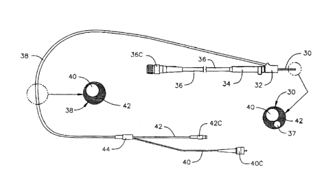
(51) Classification internationale des brevets (CIB):
  • A61B 1/04 (2006.01)
  • A61B 1/07 (2006.01)
(72) Inventeurs :
  • URAM, MARTIN (Etats-Unis d'Amérique)
(73) Titulaires :
  • BEAVER-VISITEC INTERNATIONAL, INC. (Etats-Unis d'Amérique)
(71) Demandeurs :
  • BEAVER-VISITEC INTERNATIONAL, INC. (Etats-Unis d'Amérique)
(74) Agent: PIASETZKI NENNIGER KVAS LLP
(74) Co-agent:
(45) Délivré: 2021-04-06
(22) Date de dépôt: 2011-04-29
(41) Mise à la disponibilité du public: 2011-11-17
Requête d'examen: 2019-03-08
Licence disponible: S.O.
(25) Langue des documents déposés: Anglais

Traité de coopération en matière de brevets (PCT): Non

(30) Données de priorité de la demande:
Numéro de la demande Pays / territoire Date
12/779,214 Etats-Unis d'Amérique 2010-05-13

Abrégés

Abrégé français

Un endoscope laser vidéo comporte un guide laser, un guide déclairage et un guide dimage qui constituent des guides à fibre optique se déployant à travers la sonde optique et à travers une pièce à main qui maintient la sonde. La pièce à main est reliée par un premier câble de fibre optique souple relativement long à une source dénergie laser et à une source déclairage. Par contraste, limage est transmise de la pièce à main à un site de présentation dimage par un ensemble caméra monté sur une pièce à main, et par un câble électrique relativement long. La caméra et son câble électrique peuvent être débranchés de la pièce à main et utilisés dans une pluralité de routines endoscopiques. Le reste du produit, y compris la sonde et la pièce à main, peut être éliminé après chaque routine médicale afin de garantir une procédure antiseptique.


Abrégé anglais

A laser video endoscope has a laser guide, an illumination guide and an image guide. These are fiber optical guides which extend through the optical probe and through a hand piece that supports the probe. The hand piece is connected by a first relatively long flexible optical fiber cable to a laser energy source and a source of illumination. By contrast, the image is transmitted from the hand piece to an image presentation site by a camera assembly that is mounted to a hand piece and a relatively long electrical cable. The camera and its electrical cable can be uncoupled from the hand piece and used in a plurality of endoscopic routines. The rest of the product, including the probe and the hand piece, can be disposed of after each medical routine thereby providing assurance of an antiseptic procedure.

Revendications

Note : Les revendications sont présentées dans la langue officielle dans laquelle elles ont été soumises.


-8-
THE EMBODIMENTS OF THE INVENTION IN WHICH AN EXCLUSIVE
PROPERTY OR PRIVILEGE IS CLAIMED ARE DEFINED AS FOLLOWS:
1. A single use surgical endoscope comprising:
a hand piece having a distal end comprising a distal surface and a
proximal end comprising first and second proximal surfaces;
a first opening in the first proximal surface;
a second opening in the second proximal surface;
a third opening in the distal surface;
the first opening and the second opening do not overlap;
a rigid probe extending distally from said third opening at said distal
surface of said hand piece, said probe containing an illumination guide, a
laser guide and an image guide, said illumination, laser and image guides
extending into said third opening from a proximal end of said probe and
terminating at a distal end of said probe;
said illumination guide and said laser guide extending proximally from
said third opening to said first opening of said hand piece;
said image guide extending proximally from said third opening to said
second opening of said hand piece, a proximal end of said image guide
terminating at said second proximal surface of said hand piece;
wherein said hand piece is adapted to be detachably mounted to a
camera assembly at said second proximal surface to couple said third
proximal end of said image guide to said camera assembly,
whereby, after use of the endoscope, the camera assembly is
detached from said hand piece, including said illumination, laser and image
guides being contained in said probe and said hand piece.
2. The endoscope of claim 1, wherein,
said hand piece includes a proximally extending nose for engaging
said camera assembly, said second proximal surface constituting the end of

-9-
said nose.
3. The endoscope of claim 1, wherein said image guide is constituted by
optical fibers.
4. The endoscope of claim 1, wherein said illumination guide includes a
set of optical fibers that, in said probe, are nested around said laser and
image guides to fill the space within said probe.
5. The endoscope of claim 1, wherein said camera assembly comprises
a latch adapted to detachably mount the camera assembly to the hand
piece.
6. The endoscope of claim 1, wherein an output of the camera assembly
is adapted to be coupled to a remote display by an electric cable.
7. The endoscope of claim 1, wherein said probe comprises a steel
sidewall extending from said proximal end of said probe and terminating at
said distal end of said probe, and containing said illumination guide, said
laser guide and said image guide.

Description

Note : Les descriptions sont présentées dans la langue officielle dans laquelle elles ont été soumises.

LASER VIDEO ENDOSCOK
Background Of The Invention
[0001] This invention relates in general to a medical laser video
endoscope and
more particularly to one in which the operating probe may be economically
disposed after
each use.
10002] Laser video endoscopes are known and in particular are described in
Applicant's issued Patent No. 5,121,740 issued on June 16, 1992 and Patent No.
6,997,868
issued on February 14, 2006.
[0003] The endoscopes such as the ones described in those two
patents, are reused
after autoclaving or other sterilization. Reuse occurs in large part because
of the expense of
the endoscope. The most significant expense factor is the image guide which
has a large
number of micron size optical fibers. In one endoscope 17,000 fibers were
employed thereby
providing a 17,000 pixel image.
[0004] The image guide currently used costs about $200.00. This is a major
incentive for the use of the endoscope after sterilization rather than
disposing of the
endoscope after each procedure.
[0005] This expense factor means that as a practical matter the
endoscope will be
reused after sterilization rather than disposed of.
[0006] However, there is greater security from infection if the probe
of the
endoscope can be disposed of after each usage instead of being subject to the
possibilities of
human error in the sterilization process.
CA 3036175 2019-03-08

- 2 -
[0007] Accordingly, it is a key purpose of this invention to provide
an endoseope
design for which the cost is reasonable enough to permit and encourage
disposal of the probe
after each use rather then have recourse to sterilization.
[0008] Ills a related purpose of this invention to provide this cost
improvement in
a design that maintains a probe design with which the surgeon is familiar and
which also
maintains the rest of the operating characteristics of the known laser video
endoscopes.
[0009] It is a further aspect of this invention to provide a laser
video endoscope
which is less costly than are the current designs.
CA 3036175 2019-03-08

- 3 -
Brief Description
[0010] A laser video endoscope has a laser guide, an illumination
guide and an
image guide. These are fiber optical guides which extend through the mica]
probe and
through a hand piece that supports the probe. The hand piece is connected by a
first
relatively long flexible optical fiber cable to a laser energy source and a
source of
illumination. A camera assembly is connected to the proximal end of the hand
piece and
coupled to the optical fiber image guide, A relatively long electrical cable
transmits an
electrical imago signal to a site where an image can be provided for the
surgery.
[00111 The camera and its electrical cable can be uncoupled from
the hand piece
and used in a plurality of endoscopic routines.
[0012] The rest of the product including the probe and the hand piece can be
disposed of after each medical routine thereby providing assurance of an
antiseptic
procedure.
CA 3036175 2019-03-08

- 4 -
Brief Description Of The Drawings
[0013] FIG. 1 is a schematic illustration of the prior art system
extending from the
probe 24 to the terminals I2C, 14C and 16C.
[0014] FIG. 2 is a schematic illustration of the embodiment of the
invention
disclosed herein. FIG. 2, like FIG.!, shows the system extending from the
distal probe 30 to
proximal terminals 36C, 40C and 42C.
[0015] FIG. 3 is a longitudinal view of the camera assembly 34,
cable 36 and
proximal connector 36C.
[0016] F1G. 4 is a partial longitudinal sectional view of the
camera assembly 34
showing camera housing 34, focus ring 50 and laser filter 46. FIG. 4 shows the
distal recess
52 for engaging the nose 54 of the hand piece 32.
[0017] FIG. 5 is partial sectional view of the hand piece 32.
[0018] FIG. 6 is a view similar to that of FIGs. 4 and 5 showing
the probe 30 and
hand piece 32 assembled and coupled to the camera assembly 34.
CA 3036175 2019-03-08

- 5 -
Detailed Description
[0019] Except for the prior art FIG.1, the figures are all to a
single embodiment.
[0020] As shown in FIG.!, the known laser video endoscopes have an
operating
probe 24, a hand piece 22, a cable 18 which carries a laser guide 12, an
illumination guide 14
and an image guide 16. These are all fiber optic guides which extend from the
distal end of
the probe 24 to the terminals 12C, 14C and 16C. Distal of the trifurcation
zone 20, the fiber
optic guides are combined geometrically to provide a minimum diameter cable.
[0021] The laser video endoscope of this invention includes the
probe 30, a
specifically designed hand piece 32 and a camera assembly 34 coupled to the
proximal end of
the hand piece 32.
[0022] The camera assembly 34 is directly connected to the proximal
end of the
hand piece 32. It has a relatively long electrical cable 36 which extends
proximally to a
terminal 36C which is coupled to an appropriate display mechanism including a
video screen
so that the operating surgeon can view the image during the course of
manipulating the probe.
[0023] A optical guide cable 38 extends in the proximal direction
from the hand
piece 32 to a bifurcation junction 44. This cable 38 carries the laser and
illumination guides
40 and 42 for conveying the laser energy and the illumination energy to the
probe 30. At the
bifurcation junction 44, the laser guide 40 and illumination guide 42 are
separated and
terminated at the terminals 40C and 42C for connection to thc sources of laser
energy and
illumination energy. The image carrying electrical cable 36 is about as long
as is the optical
guide cable 38. Each cable 36, 38 can be as long as required for an
installation.
[0024] As shown by the coupling mechanism in the camera assembly 34, the
optical fibers 40 from the probe 30 and hand piece 32, which carry the image
are removably
coupled to the camera so that the camera provides an electrical image that is
transmitted
Date Recue/Date Received 2020-05-11

- 6 -
along the electric cable 36 to the terminal 36C at the base where the video
displays are
provided. The camera may be any one of a number of known type and may be
specially
designed to fit the geometry of the camera assembly
[0025] Thus by positioning the camera assembly 34 at the hand piece 32, the
lengthy and expensive optical image guide is avoided. The camera assembly 34
can be
uncoupled from the hand piece 32 so that the relatively expensive camera
assembly can be
reused. This combination of reuse of the camera assembly 34 and elimination of
an extensive
length of expensive fiber optic image guide means that disposability of the
probe 30 is
economically acceptable even though the hand piece 32 and the laser and
illumination guides
40, 42 in the cable 38 are also disposed of after each medical routine.
[0026] The camera assembly 34 includes a laser filter 46 to protect
the camera film
from laser energy and to permit the surgeon to observe the operation even when
laser pulses
are firing. The probe 30 and hand piece 32 are cemented together by a known
process.
[0027] The camera assembly 34 includes a manually operated spring
latch (not
shown). The latch is of a known type. It enables readily mounting the camera
assembly 34
to the hand piece 32 and, most importantly, removing the camera assembly 34
from the hand
piece 32. In addition, the camera assembly 34 includes a focus ring 50 to
assure adequate
focus of the image provided at the proximal and of the laser fiber image guide
37 in the probe
30 and hand piece 32 onto the image receptors of the camera.
[0028] As may be seen from FIGs. 4, 5 and 6, the distal end of the camera
assembly has a recess 52 which engages a nose 54 of the hand piece 32. The
latch holds the
nose 54 in place in the recess 52.
[0029] The image guide 37 in the probe 30 and hand piece 32 costs
about $8.00.
This reduction in cost from about $200.00 to $8.00 is a major factor
encouraging disposable
use of the endoscope.
CA 3036175 2019-03-08

- 7 -
[0030] A variant on thc illustrated embodiment is an arrangement in
which the
uncoupling at the proximal end of the hand piece 32 will uncouple not only the
camera
assembly 34 but also the cable 38 so that only the probe 30 and the hand piece
32 would be
disposed of between each operation.
[0031] It has to be kept in mind that the positioning of the camera
assembly 34 at
the hand piece 32 permits a standard optical coupling of the image at the
proximal end of the
optical fiber image guide 37 to the camera assembly 34. It is not feasible to
provide a
mechanism that will permit coupling and uncoupling the fiber optic image guide
37 at a
junction other than the input to the camera. Coupling and uncoupling is
otherwise not
feasible because of the enormous number of optical fibers which would have to
he aligned for
such coupling to provide an image that is not degraded or useless.
[0032] While the foregoing description and drawings represent the
presently
preferred embodiments of the invention, it should be understood that those
skilled in the art
will be able to make changes and modifications to those embodiments without
departing from
the teachings of the invention and the scope of the claims.
[0033] For example, the image guide 37 within the probe 30 and hand piece 32
is a
fiber optic bundle of the type normally used. However, there are other means
to provide an
image guide. One such is the gradient index lens, often referred to as a GRIN
lens.
CA 3036175 2019-03-08

Dessin représentatif
Une figure unique qui représente un dessin illustrant l'invention.
États administratifs

Pour une meilleure compréhension de l'état de la demande ou brevet qui figure sur cette page, la rubrique Mise en garde , et les descriptions de Brevet , États administratifs , Taxes périodiques et Historique des paiements devraient être consultées.

États administratifs

Titre Date
Date de délivrance prévu 2021-04-06
(22) Dépôt 2011-04-29
(41) Mise à la disponibilité du public 2011-11-17
Requête d'examen 2019-03-08
(45) Délivré 2021-04-06

Historique d'abandonnement

Il n'y a pas d'historique d'abandonnement

Taxes périodiques

Dernier paiement au montant de 347,00 $ a été reçu le 2024-04-19


 Montants des taxes pour le maintien en état à venir

Description Date Montant
Prochain paiement si taxe générale 2025-04-29 347,00 $
Prochain paiement si taxe applicable aux petites entités 2025-04-29 125,00 $

Avis : Si le paiement en totalité n'a pas été reçu au plus tard à la date indiquée, une taxe supplémentaire peut être imposée, soit une des taxes suivantes :

  • taxe de rétablissement ;
  • taxe pour paiement en souffrance ; ou
  • taxe additionnelle pour le renversement d'une péremption réputée.

Les taxes sur les brevets sont ajustées au 1er janvier de chaque année. Les montants ci-dessus sont les montants actuels s'ils sont reçus au plus tard le 31 décembre de l'année en cours.
Veuillez vous référer à la page web des taxes sur les brevets de l'OPIC pour voir tous les montants actuels des taxes.

Historique des paiements

Type de taxes Anniversaire Échéance Montant payé Date payée
Requête d'examen 800,00 $ 2019-03-08
Enregistrement de documents 100,00 $ 2019-03-08
Le dépôt d'une demande de brevet 400,00 $ 2019-03-08
Taxe de maintien en état - Demande - nouvelle loi 2 2013-04-29 100,00 $ 2019-03-08
Taxe de maintien en état - Demande - nouvelle loi 3 2014-04-29 100,00 $ 2019-03-08
Taxe de maintien en état - Demande - nouvelle loi 4 2015-04-29 100,00 $ 2019-03-08
Taxe de maintien en état - Demande - nouvelle loi 5 2016-04-29 200,00 $ 2019-03-08
Taxe de maintien en état - Demande - nouvelle loi 6 2017-05-01 200,00 $ 2019-03-08
Taxe de maintien en état - Demande - nouvelle loi 7 2018-04-30 200,00 $ 2019-03-08
Taxe de maintien en état - Demande - nouvelle loi 8 2019-04-29 200,00 $ 2019-04-11
Taxe de maintien en état - Demande - nouvelle loi 9 2020-04-29 200,00 $ 2020-04-24
Taxe finale 2021-03-02 306,00 $ 2021-02-23
Taxe de maintien en état - brevet - nouvelle loi 10 2021-04-29 255,00 $ 2021-04-23
Taxe de maintien en état - brevet - nouvelle loi 11 2022-04-29 254,49 $ 2022-04-22
Taxe de maintien en état - brevet - nouvelle loi 12 2023-05-01 263,14 $ 2023-04-21
Taxe de maintien en état - brevet - nouvelle loi 13 2024-04-29 347,00 $ 2024-04-19
Titulaires au dossier

Les titulaires actuels et antérieures au dossier sont affichés en ordre alphabétique.

Titulaires actuels au dossier
BEAVER-VISITEC INTERNATIONAL, INC.
Titulaires antérieures au dossier
S.O.
Les propriétaires antérieurs qui ne figurent pas dans la liste des « Propriétaires au dossier » apparaîtront dans d'autres documents au dossier.
Documents

Pour visionner les fichiers sélectionnés, entrer le code reCAPTCHA :


Pour visualiser une image, cliquer sur un lien dans la colonne description du document. Pour télécharger l'image (les images), cliquer l'une ou plusieurs cases à cocher dans la première colonne et ensuite cliquer sur le bouton "Télécharger sélection en format PDF (archive Zip)" ou le bouton "Télécharger sélection (en un fichier PDF fusionné)".

Liste des documents de brevet publiés et non publiés sur la BDBC .

Si vous avez des difficultés à accéder au contenu, veuillez communiquer avec le Centre de services à la clientèle au 1-866-997-1936, ou envoyer un courriel au Centre de service à la clientèle de l'OPIC.


Description du
Document 
Date
(yyyy-mm-dd) 
Nombre de pages   Taille de l'image (Ko) 
Demande d'examen 2020-01-15 3 167
Modification 2020-05-11 13 517
Changement à la méthode de correspondance 2020-05-11 6 233
Description 2020-05-11 7 180
Revendications 2020-05-11 2 82
Taxe finale 2021-02-23 3 95
Dessins représentatifs 2021-03-08 1 9
Page couverture 2021-03-08 1 39
Certificat électronique d'octroi 2021-04-06 1 2 526
Dessins représentatifs 2019-05-21 1 7
Page couverture 2019-05-21 2 41
Abrégé 2019-03-08 1 20
Description 2019-03-08 7 176
Revendications 2019-03-08 3 88
Dessins 2019-03-08 6 40
Complémentaire - Certificat de dépôt 2019-03-19 1 147
Paiement de taxe périodique 2019-04-11 1 33