Note : Les descriptions sont présentées dans la langue officielle dans laquelle elles ont été soumises.
AUTOMATIC LOCKING-DEADBOLT ASSEMBLY IN A DOOR
FIELD OF THE INVENTION
[0001] The present invention relates to doors with dead bolts and a lock
assembly
to control movement of the deadbolts between extended and retracted positions
into
and out of their respective strike plates.
BACKGROUND OF THE INVENTION
[0002] Deadbolts are designed to lock a door so as to prevent intruders
from
entering a home, business or other space secured by the door. Existing
deadbolt locks
offer a certain degree of security and functionality. However, there exists a
need to
provide an improved deadbolt lock that is easy to manufacture, install and
operate while
offering a high degree of security.
SUMMARY OF THE INVENTION
[0003] According to one aspect of the present invention a lock assembly
for a
door includes a lock body having a housing; a first deadbolt supported in the
housing
for movement between a retracted position and an extended position that is
biased
toward the extended position by a spring; and a trigger mechanism mounted on
the door
separate from the lock body for engagement with a door jamb upon closure of
the door,
the trigger mechanism being adapted to hold the deadbolt in the retracted
position when
the door is open in opposition to the bias of the spring, and to permit
movement of the
deadbolt to the extended position upon engagement of the trigger mechanism
with the
door jamb.
[0004] The lock assembly according to the present invention thus enables
automatic extension of the deadbolt from the retracted to the extended
position upon
closure of the door. This is a valuable function in many situations which
require constant
security, examples including IT server rooms, valuable storage and inventory
rooms,
1
CA 3036446 2019-03-12
and also in classrooms to secure the classroom against an approaching
intruder. This
invention provides the valuable function of being able to provide a deadbolt
action by
merely closing the door and without having to find and maneuver any latch
mechanisms.
Deadbolts provide significantly greater security over basic latches, as they
tend to be
stronger and highly resistant to prying or forcing the door open.
[0005] According to another advantageous feature of the invention, the
lock
assembly further includes a bolt locking arm operatively coupled to the
deadbolt and
supported in the housing for movement between an unlocked position permitting
movement of the deadbolt from the extended position to the retracted position
and a
locked position preventing movement of the deadbolt from the extended position
to the
retracted position, wherein movement of the deadbolt from the retracted to the
extended
position causes pivoting of the bolt locking arm from the unlocked to the
locked position.
[0006] According to another advantageous feature of the invention, the
lock
assembly further includes an inner spindle cam rotatably supported in the
housing and
coupled with the deadbolt and the bolt locking arm so that rearward rotation
of the
spindle cam with respect to a front side of the housing causes pivoting of the
bolt locking
arm from the locked to the unlocked position and movement of the deadbolt from
the
extended to the retracted position.
[0007] The inner spindle cam is configured to receive the spindle of an
internal
door lever so that the spindle cam is rotated by turning the internal door
lever. This
allows the deadbolt to be released from its locked extended position and
retraction of
the deadbolt and the opening of the door from the inside by turning the
internal door
lever.
[0008] According to another advantageous feature of the invention, the
lock
assembly can further include an outer spindle cam rotatably supported in the
housing
independently of the first spindle cam and coupled to the deadbolt and the
bolt locking
arm so that rearward rotation of the outer spindle cam with respect to the
front side of
2
CA 3036446 2019-03-12
the housing causes pivoting of the bolt locking arm from the locked to the
unlocked
position and movement of the deadbolt from the extended to the retracted
position.
[0009] Providing an outer spindle cam enables release of the deadbolt
from its
deadlocked condition permitting retraction of the deadbolt and thus opening
the door
from the outside by turning an external door lever whose spindle is received
in the outer
spindle cam.
[0010] According to another advantageous feature of the invention, the
deadbolt
lock assembly can include a locking arm pivotally supported in the housing and
coupled
to the bolt locking arm, the locking arm being adapted to pivot in response to
engagement with a cam of a keyed cylinder received in a side wall of the
housing to
thereby cause pivoting of the bolt locking arm from the locked position to the
unlocked
position.
[0011] In such an embodiment of the invention, the deadlocked condition
of the
deadbolt can be released by turning the keyed cylinder from the outside with
an
authorized key.
[0012] According to another advantageous feature of the invention, the
lock
assembly can include a second deadbolt supported in the housing for movement
between a retracted and an extended position in which the first and second
deadbolt
are coupled for simultaneous movement between their respective retracted and
extended positions, and so that movement of the second deadbolt from the
retracted to
the extended position is blocked when the first deadbolt is held in its
retracted position.
[0013] According to another advantageous feature of the invention, the
lock
assembly can include a third deadbolt supported in the housing for movement
between
a retracted and an extended position, in which the first, second and third
deadbolts are
coupled for simultaneous movement between their respective retracted and
extended
positions, and so that movement of the second and third deadbolts from their
respective
3
CA 3036446 2019-03-12
retracted to their extended positions is blocked when the first deadbolt is
held in its
retracted position.
[0014] According to another advantageous feature of the invention, the
first,
second and third deadbolts are coupled with each other by a gear member
rotatably
supported in the housing so that rotation of the gear member in a clockwise
(OW)
direction causes movement of the first, second and third deadbolts from their
respective
extended positions to their retracted positions and counter-clockwise (COW)
movement
of the gear member causes movement of the deadbolts from their respective
retracted
positions to their extended positions.
BRIEF DESCRIPTION OF THE DRAWINGS
[0015] The above and other advantages of the invention will be further
described
and appreciated by those skilled in the art by reference to the following
detailed
description of the invention, the claims and the appended drawings in which:
[0016] FIG. 1 is a perspective view of the exterior of the lock body
of the
new locking deadbolt assembly;
[0017] FIG. 2 is a side elevation view of the interior of the new
locking
deadbolt assembly of FIG. 1 taken along the direction of the arrows A-A with
the cover
removed and the deadbolts in the extended position;
[0018] FIG. 3 is an exploded view of an embodiment of the lock body;
[0019] FIG. 4 is a side elevation view of the interior of the new
locking
deadbolt assembly with the inner spindle cam slightly rotated rearwardly with
respect to
the front face of the lock body housing;
4
CA 3036446 2019-03-12
[0020] FIG. 5 is a side elevation view of the interior of the new
locking
deadbolt assembly with the inner spindle cam rotated further rearwardly from
the
position shown in FIG. 4;
[0021] FIG. 6 is a side elevation view of the interior of the new
locking
deadbolt assembly with the inner spindle cam rotated further rearwardly from
the
position shown in FIG. 5 and with the deadbolts in the retracted position;
[0022] FIG. 7A is a top view of a first embodiment of a locking
slider
according to the invention;
[0023] FIG. 7B is a side view of the first embodiment of the locking
slider;
[0024] FIG. 70 is a bottom view of the first embodiment of the
locking slider;
[0025] FIG. 8A is a top view of a second embodiment of a locking
slider
according to the invention;
[0026] FIG. 8B is a side view of the second embodiment of the locking
slider;
[0027] FIG. 80 is a bottom view of the second embodiment of the
locking
slider;
[0028] FIG. 9 is an enlarged side elevation view of a portion of the
new
locking deadbolt assembly of FIG. 6 showing the interaction between the key
cylinder
cam and the tongue of the locking arm;
[0029] FIG. 10A is a top, front and left side perspective view of the
trigger
mechanism in the holding position;
CA 3036446 2019-03-12
[0030] FIG. 10B is a front elevation view of the trigger mechanism of
Figure
10A;
[0031] FIG. 100 is a cross-sectional view of the trigger mechanism of
FIG.
10B taken along the direction of the arrows B-B;
[0032] FIG. 10D is a side elevation view of the trigger mechanism of
Figure
10A;
[0033] FIG. 11A is a top, front and left side perspective view of the
trigger
mechanism in the release position;
[0034] FIG. 11B is a front elevation view of the trigger mechanism of
Figure
11A;
[0035] FIG. 110 is a cross-sectional view of the trigger mechanism of
FIG.
11B taken along section line A-A;
[0036] FIG. 11D is a side elevation view of the trigger mechanism of
Figure
11A;
[0037] FIG. 12 is a perspective view of the trigger mechanism partly
in
phantom installed on the top of a door;
[0038] FIG. 13A shows a cross-section of the trigger mechanism of
FIG. 12
along section line C-C in a view in the direction of the arrow D, with the
trigger
mechanism in the holding position;
[0039] FIG. 13B shows a cross-section of the trigger mechanism of
FIG. 12
along section line C-C in a view in the direction of the arrow D, with the
trigger
6
CA 3036446 2019-03-12
mechanism in the release position after closing the door, with the deadbolt
received in
a strike plate in the doorjamb;
[0040] FIG. 14A is a schematic diagram of an embodiment of the lock
assembly according to the present invention showing a pivot mechanism for
movement
of a top deadbolt in a horizontal direction, with the top deadbolt in the
retracted position;
and
[0041] FIG. 14B shows the embodiment of FIG. 14A with the top
deadbolt in
the extended position.
[0042] Throughout all the Figures, the same or corresponding elements
are
identified by same reference numeral. The embodiments are to be understood as
illustrative of the invention and not as limiting in any way. It will also be
understood that
the figures are not necessarily to scale and that the embodiments are
sometimes
illustrated by graphic symbols, phantom lines, diagrammatic representations
and
fragmentary views. In certain instances, details which are not necessary for
an
understanding of the present invention or which render other details difficult
to perceive
have been omitted.
DETAILED DESCRIPTION OF PREFERRED EMBODIMENTS
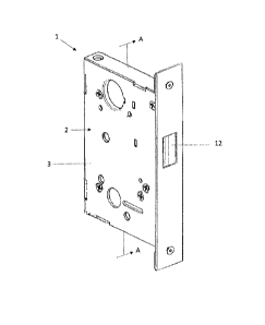
[0043] Referring to FIG. 1, an embodiment of a lock body of the lock
assembly
according to the present invention is shown and is generally designated by
reference
numeral 1. The lock body 1 comprises a housing 2 for housing the lock
components.
One of the side walls of the housing comprises a cover 3 which forms a closure
of the
lock body 1.
[0044] FIGS. 2 and 3 show the relative arrangement of the components of
the
lock body 1. FIG. 2 shows a side elevation view of the lock body 1 taken along
section
line A-A with the cover 3 removed. FIG. 3 shows an exploded view of the lock
body 1.
7
CA 3036446 2019-03-12
Referring to FIG. 2, the housing 2 includes a side wall 2.1, and top, bottom,
front and
rear walls 2.2, 2.3, 2.4 and 2.5, respectively. The front wall 2.4 has an
opening for the
front deadbolt 12. A face plate 2.6 is secured to the front wall of the
housing 2 and has
an opening which corresponds to the opening in the front wall 2.4. In the
housing,
actuators 12.1, 11, 7 and are mounted and coupled, respectively, to front, top
and
bottom deadbolts 12, 11.1, 7.1 for moving the front, top and bottom
deadbolts12, 11, 7
between their respective retracted and extended positions. The top and bottom
deadbolts 11.1, 7.1 are connected to the top and bottom actuators 11, 7 via
their
respective extension rods 11.2, 7.2. The front, top and bottom deadbolts 12
11.1, 7.1
are shown in their respective extended positions. The front, top and bottom
deadbolts
12, 11.1, 7.1 are coupled to each other via main gear 9 and small gear 6. The
main gear
9 is rotatably mounted in the housing 2 and has a toothed outer circumference
and drive
pins 9.1 and 9.2 extending from either side wall of the gear 9. Bottom
deadbolt actuator
7 and front deadbolt actuator 12.1 have oblong holes 7.2 and 12.3 which
respectively
receive the drive pins 9.1 and 9.2 of the main gear 9. The top actuator 11 has
a serrated
or toothed portion and is coupled to the main gear 9 via the toothed portion
that mates
with small gear 6.
[0045] The front deadbolt 12 is biased toward the extended position by
compression spring 14. One end of the compression spring 14 is secured to
spring
anchor 13 and the other end to a rear face of the front deadbolt 12.
[0046] The lock body 1 further includes a bolt locking arm 10 for
deadlocking the
front deadbolt 12 in its extended position. The bolt locking arm 10 is pivotal
about pin
10.2 between an upper locked position and a lower unlocked position. In the
locked
position shown in FIG. 2, locking finger 10.3 of bolt locking arm 10 is
aligned with
shoulder 12.4 of the front deadbolt actuator 12.1 and prevents movement of the
front
deadbolt 12 from its extended to its retracted position.
[0047] With continuing reference to FIGS. 2 and 3, the lock body 1 also
includes
inner spindle cam 8.1 and outer spindle cam 8.2 for moving the deadbolts from
their
8
CA 3036446 2019-03-12
respective extended positions to their retracted positions. The spindle cams
8.1, 8.2 are
rotatably mounted in the housing 2 through openings 8.3 for receiving the
spindle of
respective external and internal door levers (not shown) so that the spindle
cams 8.1,
8.2 can be independently rotated by turning the external or internal door
lever.
[0048] The spindle cams 8.1, 8.2 are operatively coupled with the bolt
locking arm
via locking slider 5 and locking arm 4 so that the bolt locking arm 10 is
pivoted
downward to its unlocked position when spindle cam 8.1 or 8.2 is rotated to
return the
front deadbolt 12 to its retracted position. The locking arm 4 has a top end
4.1 and a
bottom end 4.4 and is supported in the housing 2 for pivoting about its top
end 4.1.
Between its top and bottom ends 4.1, 4.4, locking arm 4 is provided with an
opening 4.2
which receives bolt locking arm pin 10.1. The locking slider 5 is mounted on
the bottom
end 4.4 of the locking arm 4 and is supported in horizontal slots 5.2 provided
in the cover
3 and sidewall 2.1 via ridges 5.1 provided on opposing sides of the locking
slider 5 for
movement in the horizontal direction.
[0049] The return of the deadbolts from their respective extended
positions to
their retracted positions is described in more detail below.
[0050] FIG. 4 shows the position of the spindle cam 8.1 after a partial
CCW
rotation from its position shown in FIG. 2 which corresponds to rearward
rotation with
respect to the front wall of the housing. CCW rotation of spindle cam 8.1
causes it to
engage the bottom slanted surface 5.3 of locking slider 5 resulting in
movement of
locking slider 5 toward the right out of opening 8.1.1 of spindle cam 8.1. As
a result,
locking arm 4 is pivoted CCW about its top end 4.1, which in turn causes
downward
pivoting of bolt locking arm 10 about pin 10.2 via engagement of opening 4.2
of locking
arm 4 with bolt locking arm pin 10.1.
[0051] FIG. 5 shows the position of the components of the lock body 1
after further
CCW rotation of internal spindle cam 8.1 from its position shown in FIG. 4.
Internal
spindle cam 8.1 has engaged vertical portion 12.2 of front deadbolt actuator
12.1 and
9
CA 3036446 2019-03-12
has moved front deadbolt 12 rearward toward its retracted position. This has
caused
main gear 9 to rotate CW via engagement of drive pin 9.2 with oblong hole 12.3
of front
deadbolt actuator 12.1. CW rotation of main gear 9 also causes movement of top
and
bottom actuators 11, 7 towards their retracted positions via interaction of
drive pin 9.1
with oblong hole 7.2 of bottom actuator 7 and CCW rotation of small gear 6.
Locking
arm 4 has been further pivoted CCW through interaction of locking slider 5
with surface
8.1.2 of spindle cam 8.1. Spring 15 which is mounted in the housing and
attached to the
bottom end of locking arm 4 is tensioned and biases locking arm 4 toward the
left. As a
result of engagement of locking slider 5 on surface 8.1.2 of spindle cam 8.1,
bolt locking
arm 10 is held in the unlocked position against the bias of tensioned spring
15.
[0052] FIG. 6 shows the components of the lock body 1 after further CCW
rotation
of inner spindle cam 8.1 from its position shown in FIG. 5 with the deadbolt
actuators in
their fully retracted positions. Further rearward movement of the front
deadbolt actuator
12.1 has caused further CW rotation of the main gear 9, and as a result,
further retraction
of the top and bottom actuators 11, 7. In this position, spring 14 is
compressed between
spring anchor 13 and front deadbolt 12.
[0053] In certain embodiments, the locking deadbolt assembly can be
constructed so that the deadbolts can either be returned to their retracted
positions by
actuating either of the internal or external door levers or only to permit
return of the
deadbolts by actuating the internal door lever. This can be accomplished by
correspondingly designing the locking slider 5. FIGS. 7A-C show an embodiment
of the
locking slider 5 which is constructed so that the bolt locking arm 10 can be
disengaged
from its deadbolting position and the deadbolts returned to their retracted
position by
actuating either of the external or internal door levers. FIGS. 7 A-C show,
respectively,
top, side and bottom views of the locking slider 5. In this embodiment, the
locking slider
has a smooth slanted configuration along the entire length L of its end facing
the
spindle cam openings 8.1.1, 8.2.1. FIGS. 7A-C further show the ridges 5.1 with
which
the locking slider 5 is supported in the horizontal slots 5.2 of the housing,
and opening
5.4 with which the locking slider 5 is mounted on the bottom end 4.4 of
locking arm 4. In
CA 3036446 2019-03-12
the embodiment shown in FIGS. 7A-C, both spindle cams 8.1 and 8.2 interact
with the
locking slider 5 in the manner described for the inner spindle cam 8.1 above.
Thus,
rotation of either spindle cam 8.1 or 8.2 causes the locking slider 5 to move
in a
horizontal direction toward the front side of the housing 2 which results in
COW pivoting
of the locking arm 4 and downward pivoting of bolt locking arm 10 to its
unlocked
position.
[0054] FIGS. 8A-C show an embodiment of the locking slider 5 which is
configured so that the bolt locking arm 10 can only be disengaged from its
deadbolting
position and the deadbolts returned to their retracted position by turning the
internal door
lever, but not by turning the external door lever. FIGS. 8 A-C are,
respectively, top, side
and bottom views of the locking slider 5. In this embodiment, the locking
slider 5 has a
smooth slanted configuration in the region of its end that engages with the
spindle cam
opening 8.1.1 of the inner spindle cam 8.1 and a square configuration 5.5 in
the region
of its end that engages with the spindle cam opening 8.2.1 of the outer
spindle cam 8.2.
Engagement of the square configuration in the spindle cam opening 8.2.1 blocks
COW
rotation of the spindle cam 8.2 and prevents the locking slider 5 from being
pushed out
of the spindle cam opening 8.2.1. As a result, the locking arm 4 cannot be
pivoted COW
to disengage bolt locking arm 10 from its deadbolting position by turning the
outer
spindle cam 8.2 with an external door lever. However, this embodiment still
permits
disengagement of the bolt locking arm 10 from its deadbolting position by
manually
rotating the inner spindle cam 8.1 using the internal door lever.
[0055] The bolt locking arm 10 can also be disengaged from its
deadbolting
position by turning a key cylinder 25 received in the housing and having a cam
26 as
shown in FIG. 9. CW turning of the key cylinder 25 causes the cam 26 to engage
with
the tongue 4.3 of locking arm 4 and to push the tongue 4.3 downward, thereby
causing
CCW rotation of locking arm 4 about top end 4.1, and downward pivoting of bolt
locking
arm 10.
11
CA 3036446 2019-03-12
[0056] In the retracted position of the deadbolts, spring 14 is
tensioned and the
deadbolts are biased towards their extended positions. The deadbolts are
coupled via
the main gear 9 and small gear 6 such that holding one of the deadbolts in its
retracted
position will block and prevent movement of the other deadbolts from their
retracted to
their extended positions. For example, holding the top deadbolt 11.1 in its
retracted
position prevents the bottom deadbolt 7.1 and front deadbolt 12 from moving to
their
respective extended positions. Upon release of the top deadbolt 11.1, the
front deadbolt
12 is urged by spring 14 towards its extended position. This results in CCW
rotation of
the main gear 9, which causes the top and bottom deadbolts 11.1, 7.1 to move
to their
respective extended positions. Movement of the front deadbolt 12 to its
extended
position also causes CW rotation of the inner and outer spindle cams 8.1, 8.2
to positions
in which the spindle cam openings 8.1.1, 8.2.1 are oriented horizontally. This
permits
locking slider 5 to move to the left driven by tensioned spring 15 to engage
in spindle
cam openings 8.1.1, 8.2.1 which causes CW rotation of locking arm 4, which in
turn
results in the upward pivoting of bolt locking arm 10 to its deadbolting
position.
[0057] Referring now to FIGS. 10A-D and FIGS. 11A-D, there is shown an
embodiment of a trigger mechanism 30 according to the present invention for
releasably
holding one of the deadbolts in its retracted position. FIGS. 10A-D show the
trigger
mechanism in its holding position in which the locking plate is inclined with
respect to
the base plate 32 and the upper plate 33. FIGS. 11A-D show the trigger
mechanism 30
in its release position in which the locking plate 35 is pivoted downwardly to
form a
smaller angle with the base plate 32 and the upper plate 33.
[0058] The trigger mechanism 30 has a base plate 32, an upper plate 33
secured
to the base plate 32 in spaced-apart and parallel relationship via legs 33.1,
3.2, a locking
plate 35 arranged between the base plate 32 and the upper plate 33 and a
trigger plate
36. The locking plate 35 has adjustable screws 35.1 received in threads
provided at front
corners of the locking plate 35. The screws extend upwardly through openings
35.2 in
the upper plate 33. The locking plate 35 is mounted to pivot between upper
position and
12
CA 3036446 2019-03-12
lower positions and is biased toward the upper position by springs 34
positioned
between the base plate 32 and the locking plate 35.
[0059] The trigger plate 36 is pivotally mounted in slots 33.3 in the
upper plate 33
for pivoting between an upper and a lower position and has a raised portion
36.1 at its
front edge for facilitating engagement of the trigger plate 36 with the door
jamb.
Downward pivoting of the trigger plate 36 causes its front edge to bear down
on the
screws received in the locking plate 35 and causes downward pivoting of the
locking
plate 35 toward its lower position in opposition to the bias of the springs
34. The screws
can be rotated to move them in or out to adjust the distance the trigger plate
36 has to
pivot downwards to cause downward pivoting of the locking plate 35. This
allows
adjustment of the trigger mechanism to accommodate the distance between the
top of
the door and the door jamb when mounting the trigger mechanism in a recess
having a
predetermined depth in the top of the door.
[0060] The base plate 32, upper plate 33, locking plate 35 and trigger
plate 36
are provided with apertures 37 for receiving the top deadbolt therein. The
diameter D
of the aperture of the locking plate 35 is dimensioned so that in the lowered
position of
the locking plate 35 the top deadbolt 11.1 can extend unrestrained through the
apertures
of the base plate 32, the locking plate 35, the upper plate 33 and the trigger
plate, and
in the lowered position of the locking plate 35, the edges of the locking
plate 35 engage
the surface of the top deadbolt 11.1 so as to prevent upward movement of the
top
deadbolt 11.1. The aperture of the trigger plate 36 is dimensioned to permit
free passage
of the top deadbolt in the upper and lower position of the trigger plate 36.
[0061] The trigger mechanism 30 is mounted on the door so that its
apertures 37
are aligned with the deadbolt that is to be releasably held in its retracted
position. FIG.
12 illustrates the arrangement of the trigger mechanism 30 in a recess 40.1 on
the top
of a door 40 so that its apertures are aligned with the top deadbolt 11.1. The
trigger
mechanism 30 is mounted recessed relative to the top door edge so as to allow
unobstructed closing of the door 40, while at the same time enabling
engagement of the
13
CA 3036446 2019-03-12
trigger plate 36 with the door jamb 41 when the door is closed. FIG. 12 also
shows the
lock body 1 mounted on the front face of the door with extension rod 11.2
which couples
the top bolt 11.1 to the top actuator in the lock body 1.
[0062] FIGS. 13A and 13B schematically illustrate the interaction of the
trigger
mechanism 30 with the top bolt 11.1 in the holding position and the release
position.
FIGS. 13A and 13B show the trigger mechanism of FIG. 12 in a cross-section
along
section line C-C in a view taken in the direction of the arrow D. FIG. 13A
shows the
trigger mechanism 30 when the door is open, and FIG. 13B shows the trigger
mechanism 30 when the door is closed and the trigger plate 36 has been pivoted
downward as a result of its contact with the door jamb 41 and the top deadbolt
11.1 has
extended into a strike plate in the door jamb 41. When the door is open, as
illustrated in
FIG. 13A, the trigger mechanism 30 is in the holding position with the locking
plate in
the lower position. In this position the edges of the aperture of the locking
plate engage
on the surface of the top deadbolt 11.1 so as to hold the deadbolt in the
retracted
position. When the door is closed as illustrated in FIG. 13B, the locking
plate is pivoted
to its lower position and deadbolt 11.1 is permitted to move to its extended
position.
[0063] In another embodiment, the top and/or bottom deadbolts are
mounted for
movement in the horizontal direction when actuated by the top or bottom
actuators and
to engage in strike plates mounted in the adjacent side jamb of the door. In
this
embodiment, the top and/or bottom deadbolts are connected to the top or bottom
actuators via a pivot mechanism 50 as schematically illustrated in FIG. 14A-B
for top
deadbolt 11.1. The top deadbolt 11.1 is supported in a casing 52 mounted on
the door
and is connected to the top actuator (not shown) via L-shaped member 51 and
extension
rod 11.2. Movement of the top actuator 11 from its retracted to its extended
position
causes upward movement of extension rod 11.2 and pivoting of the L-shaped
member
about pivot point P. This results in the pivoting of the upper leg of the L
shaped member
to the right and movement of the top deadbolt 11.1 from its retracted position
to its
extended position into a strike plate mounted in the side doorjamb.
14
CA 3036446 2019-03-12
[0064] The invention has been explained with reference to an exemplary
embodiment including 3 deadbolts. However, embodiments including 2 deadbolts
or
only a single deadbolt are also within the scope of the invention. Moreover,
= embodiments of the invention with only 2 or a single deadbolt will
provide the
deadbolting function and door lever actuated deadbolt retraction described in
connection
with the embodiment including three deadbolts. For example, the lock assembly
1 can
include the top deadbolt actuator 11 and top deadbolt 11.1, but not the bottom
deadbolt
actuator 7, the bottom deadbolt 7.1 and the front deadbolt 12. Such an
embodiment will
still include the front deadbolt actuator 12.1.
[0065] In an embodiment in which the front deadbolt 12 is the only
deadbolt, the
trigger mechanism can be mounted on the front edge of the door so that the
apertures
are aligned with the front deadbolt. In this embodiment, the front deadbolt 12
preferably
has round cross-section corresponding to the apertures of the trigger
mechanism. The
lock body 1 in such an embodiment is mounted recessed with respect to the
front edge
of the door to permit corresponding recessed mounting of the trigger mechanism
as
explained above in connection with the mounting of the trigger mechanism on
the top
edge of the door.
[0066] What is claimed as new and desired to be protected is set forth in
the
appended claims and includes equivalents of the elements recited therein.
CA 3036446 2019-03-12