Note : Les descriptions sont présentées dans la langue officielle dans laquelle elles ont été soumises.
HEMOSTAT-STYLE ULTRASONIC SURGICAL INSTRUMENT
WITH CLAMP FORCE-LIMITING FEATURE
_
BACKGROUND
Technical Field
[0001] The present disclosure relates to ultrasonic surgical
instruments and,
more particularly, to a hemostat-style ultrasonic surgical instrument
configured to
limit clamping force to a maximum clamping force.
Background of Related Art
[0002] Ultrasonic surgical instruments utilize ultrasonic energy,
i.e., ultrasonic
vibrations, to treat tissue. More specifically, ultrasonic surgical
instruments utilize
mechanical vibration energy transmitted at ultrasonic frequencies to
coagulate,
cauterize, fuse, seal, cut, desiccate, and/or fulgurate tissue to effect
hemostasis.
[0003] Ultrasonic surgical instruments typically employ a
transducer coupled
to a handle of the ultrasonic surgical instrument and configured to produce
ultrasonic
energy for transmission along a waveguide to an end effector of the ultrasonic
surgical instrument that is designed to treat tissue with the ultrasonic
energy. The
transducer may be driven by an ultrasonic generator that is on-board, e.g., on
or
within the handle of the ultrasonic surgical instrument, or remotely disposed,
e.g., as
a set-top box connected to the ultrasonic surgical instrument via a surgical
cable.
The end effector of the ultrasonic surgical instrument may include a blade
that
receives the ultrasonic energy from the waveguide for application to tissue
and a jaw
member configured to clamp tissue between the blade and the jaw member to
facilitate treatment thereof.
1
CA 3040369 2019-04-16
SUMMARY
- [0004] As used herein, the term "distal" refers to the portion
that is described
. which is further from a user, while the term "proximal" refers to the
portion that is
described which is closer to a user. Further, any or all of the aspects
described
herein, to the extent consistent, may be used in conjunction with any or all
of the
other aspects described herein.
[0005] Provided in accordance with aspects of the present
disclosure is an
ultrasonic surgical instrument including a first shaft member, a jaw member
extending distally from the first shaft member, a second shaft member, an
ultrasonic
blade extending distally from the second shaft member and positioned to oppose
the
jaw member, and a force-limiting hinge assembly operably coupling the first
and
second shaft members with one another such that movement of the first and
second
shaft members relative to one another between a spaced-apart position and an
approximated position moves the jaw member and the ultrasonic blade relative
to
one another between an open position and a clamping position for clamping
tissue
therebetween. The force-limiting hinge assembly includes a hinge arm fixedly
engaged to one of the first or second shaft members at a first end thereof and
pivotably coupled to the other of the first or second shaft members at a
second end
thereof. The hinge arm is configured to flex to regulate a clamping force
applied to
tissue clamped between the jaw member and the ultrasonic blade.
[0006] In an aspect of the present disclosure, the first end of
the hinge arm is
fixedly engaged with the second shaft member and the second end of the hinge
arm
is pivotably coupled to the first shaft member.
2
CA 3040369 2019-04-16
[0007] In another aspect of the present disclosure, the first end
of the hinge
arm is monolithically formed with the one of the first or second shaft
members.
[0008] In still another aspect of the present disclosure, a pivot
pin pivotably
,
couples the second end of the hinge arm with the other of the first or second
shaft
members.
[0009] In yet another aspect of the present disclosure, the hinge
arm is
resiliently flexible.
[0010] In still yet another aspect of the present disclosure, the
jaw member
includes a structural body and a tissue pad supported on the structural body.
[0011] In another aspect of the present disclosure, a transducer
and
waveguide assembly is supported by the second shaft member. The transducer and
waveguide assembly includes an ultrasonic transducer and an ultrasonic
waveguide
coupled to and extending distally from the ultrasonic transducer. The
ultrasonic
blade is defined at a distal end of the ultrasonic waveguide.
[0012] In another aspect of the present disclosure, the transducer
and
waveguide assembly is removable from the second shaft member.
[0013] In yet another aspect of the present disclosure, each of
the first and
second shaft members includes a handle disposed towards a proximal end
thereof.
The handles are configured to facilitate movement of the first and second
shaft
members relative to one another between the spaced-apart position and the
approximated position.
3
CA 3040369 2019-04-16
[0014] In still another aspect of the present disclosure, an activation
button is
disposed on the second shaft member. The activation button is selectively
activatable to supply ultrasonic energy to the ultrasonic blade.
[0015] In still yet another aspect of the present disclosure, the hinge
arm
regulates the clamping force applied to tissue clamped between the jaw member
and
the ultrasonic blade by flexing to inhibit the clamping force from exceeding a
maximum clamping force.
[0016] Another ultrasonic surgical instrument provided in accordance with
aspects of the present disclosure includes a first shaft member including a
shaft
portion and a jaw member extending distally from the shaft portion, a second
shaft
member supporting a transducer and waveguide assembly, and a force-limiting
hinge assembly. The transducer and waveguide assembly includes an ultrasonic
transducer and an ultrasonic waveguide coupled to and extending distally from
the
ultrasonic transducer. An ultrasonic blade is defined at a distal end of the
ultrasonic
waveguide and positioned to oppose the jaw member. The force-limiting hinge
assembly operably couples the first and second shaft members with one another
such that movement of the first and second shaft members relative to one
another
between a spaced-apart position and an approximated position moves the jaw
member and the ultrasonic blade relative to one another between an open
position
and a clamping position for clamping tissue therebetween. The force-limiting
hinge
assembly includes a hinge arm fixedly engaged to the second shaft member at a
first
end thereof and pivotably coupled to the first shaft member at a second end
thereof.
The hinge arm is configured to flex to regulate a clamping force applied to
tissue
clamped between the jaw member and the ultrasonic blade. The ultrasonic
surgical
4
CA 3040369 2019-04-16
instrument may further include any of the other aspects and/or features
detailed
hereinabove or otherwise herein.
BRIEF DESCRIPTION OF THE DRAWINGS
[0017] The above and other aspects and features of the present disclosure
will become more apparent in light of the following detailed description when
taken in
conjunction with the accompanying drawings wherein like reference numerals
identify similar or identical elements and:
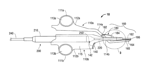
[0018] FIG. 1 is a side view of a hemostat-style ultrasonic surgical
instrument
provided in accordance with the present disclosure;
100191 FIG. 2 is an enlarged, side view of a transducer and waveguide
assembly of the ultrasonic surgical instrument of FIG. 1; and
100201 FIG. 3 is an enlarged, side view of the area of detail indicated
as "3" in
FIG. 1, with the transducer and waveguide assembly removed.
DETAILED DESCRIPTION
[0021] Referring to FIG. 1, a hemostat-style ultrasonic surgical
instrument
provided in accordance with the present disclosure is shown generally
identified by
reference numeral 10. Ultrasonic surgical instrument 10 is configured to
operably
couple to an ultrasonic surgical generator (not shown) and generally includes
two
elongated shaft members 110a, 110b, an activation button 140, an end effector
assembly 160, a force-limiting hinge assembly 180, and a transducer and
waveguide
assembly 200.
[0022] Each shaft member 110a, 110b includes a handle 111a, 111b disposed
towards the proximal end 112a, 112b thereof. Each handle 111a, 111b defines a
finger hole 113a, 113b therethrough for receiving a finger of the user. One of
the
CA 3040369 2019-04-16
shaft members, e.g., shaft member 110a, includes a jaw member 164 of end
effector
assembly 160 extending from the distal end 114a thereof. The other shaft
member,
e.g., shaft member 110b, defines an elongated body 115 configured to receive
transducer and waveguide assembly 200 therethrough. Elongated body 115 mounts
activation button 140 thereon. Transducer and waveguide assembly 200 may be
releasably insertable through elongated body 115 into engagement therewith, or
may
be permanently affixed within elongated body 115. In either configuration,
elongated
body 115 is configured to receive and engage transducer and waveguide assembly
200 therein such that blade 162 of transducer and waveguide assembly 200
extends
distally from distal end 114b of elongated body 115 and is positioned to
oppose jaw
member 164 of shaft member 110a. Shaft members 110a, 110b are coupled to one
another towards the distal ends 114a, 114b, respectively, thereof via force-
limiting
hinge assembly 180, as detailed below, to enable jaw member 164 to pivot
relative
to blade 162 to clamp tissue therebetween.
[0023]
With reference to FIG. 2, transducer and waveguide assembly 200
includes a housing 210, an ultrasonic transducer 212, e.g., a piezoelectric
stack,
disposed within housing 210, an ultrasonic horn 214 disposed within housing
210
and coupled to ultrasonic transducer 212, and an ultrasonic waveguide 220
coupled
to ultrasonic horn 214, e.g., via a releasable threaded engagement, within
housing
210 and extending distally from housing 210 to define an ultrasonic blade 162
of end
effector assembly 160 at the distal of ultrasonic waveguide 220, distally-
spaced from
housing 210. Transducer and waveguide assembly 200 further includes a cable
240
extending proximally from housing 210 to enable connection of transducer and
waveguide assembly 200 to an ultrasonic generator (not shown). Alternatively,
cable
6
CA 3040369 2019-04-16
240 may extend from another suitable location on ultrasonic surgical
instrument 10,
e.g., handle 111b.
[0024] Piezoelectric stack 214 includes a plurality of piezoelectric
elements
stacked with electrodes disposed therebetween and is configured to convert
electrical energy provided by the ultrasonic generator (not shown) and
supplied
thereto via wires 242 extending through cable 240 (FIG. 1) into mechanical
energy
that is transmitted to ultrasonic waveguide 220 via ultrasonic horn 214.
Ultrasonic
waveguide 220, in turn, is configured to transmit the mechanical energy to
blade 162
at the distal end of ultrasonic waveguide 220 such that blade 162 oscillates
at
ultrasonic frequencies.
[0025] Referring also to FIG. 1, transducer and waveguide assembly 200
may
further include an external contact 250 disposed on housing 210 and
electrically
coupled to a wire 252 extending through housing 210 and cable 240 to the
ultrasonic
generator (not shown). Contact 250 is configured to mate with a corresponding
contact 142 disposed within elongated body 115 of shaft member 110b and
electrically coupled to activation button 140 of ultrasonic surgical
instrument 10 to
enable the selective activation of ultrasonic surgical instrument 10.
Activation button
140, more specifically, may be selectively activatable in a first position and
a second
position to supply electrical energy from the ultrasonic generator to
transducer and
waveguide assembly 200 for operating ultrasonic instrument 10 in a low-power
mode
of operation and a high-power mode of operation, respectively.
[0026] Continuing with reference to FIGS. 1 and 2, ultrasonic waveguide
220,
as noted above, extends distally from housing 210 and defines blade 162 of end
effector assembly 160 at the distal end thereof. Due to the coupling of shaft
members 110a, 110b towards the distal ends 114a, 114b, respectively, thereof,
via
7
CA 3040369 2019-04-16
force-limiting hinge assembly 180, handles 111a, 111b may be moved relative to
one
another to thereby pivot jaw member 164 relative to blade 162 between an open
position, wherein jaw member 164 is spaced-apart from blade 162, and a closed
position, wherein jaw member 164 is approximated relative to blade 162 in
juxtaposed alignment therewith for clamping tissue therebetween.
[0027] End effector assembly 160 includes blade 162 and jaw member 164.
Blade 162 may define a linear configuration or a curved configuration curved
in any
direction relative to jaw member 164, for example, such that the distal tip of
blade
162 is curved towards jaw member 164, away from jaw member 164, or laterally
(in
either direction) relative to jaw member 164. Blade 162 may further define a
multi-
curve configuration wherein blade 162 includes multiple curves and/or is
curved in
multiple directions.
[0028] Jaw member 164 includes a substantially rigid (within material and
manufacturing tolerances) structural jaw body 165 which may be monolithically
formed with or otherwise engaged to the distal end 114a of shaft member 110a.
jaw
member 164 further includes a tissue pad 166 supported on structural jaw body
165
and positioned to oppose blade 162. Tissue pad 166 is formed at least
partially from
a compliant material, e.g., PTFE, and serves to facilitate clamping tissue and
maintaining the clamp on tissue when blade 162 is activated. Tissue pad 166
also
protects blade 162, structural jaw body 165, and surroundings from damage by
inhibiting contact between blade 162 and structural jaw body 165.
[0029] Referring to FIG. 3, in conjunction with FIG. 1, as noted above,
first and
second shaft members 110a, 110b are coupled to one another towards the distal
ends 114a, 114b, respectively, thereof via force-limiting hinge assembly 180.
Force-
limiting hinge assembly 180 includes a pivot pin 182 and a living hinge arm
184.
8
CA 3040369 2019-04-16
Living hinge arm 184, as detailed below, is configured to provide a force-
limiting
feature whereby the clamping force applied to tissue clamped between blade 162
and jaw member 164 is limited to a maximum clamping force. The material
forming
living hinge arm 184, the length of living hinge arm 184, the shape of living
hinge arm
184, the thickness of living hinge arm 184, and/or other factors are tailored
to provide
a living hinge arm 184 that acts as a constant-force spring to limit the
clamping force
to a desired maximum clamping force, as detailed below.
100301
Living hinge arm 184 includes a first end portion 185 and a second end
portion 187. First end portion 185 of living hinge arm 184 is fixed, e.g.,
monolithically
formed with or otherwise engaged, with one of the shaft members, e.g.,
elongated
body 115 of second shaft member 110b, while second end portion 187 of living
hinge
arm 184 is pivotably coupled to the other of the shaft members, e.g., first
shaft
member 110a, via pivot pin 182. Second end portion 187, more specifically, may
be
disposed on one side of first shaft member 110a or may be received within a
slot
(not explicitly shown) defined within first shaft member 110a such that a
pivot
aperture 188 defined through second end portion 187 of living hinge arm 184 is
aligned with a pivot aperture 119 defined through first shaft member 110a.
Pivot pin
182 extends through the aligned apertures 119, 188 to pivotably couple second
end
portion 187 of living hinge arm 184 with first shaft member 110a. In this
manner, first
shaft member 110a is movable relative to second shaft member 110b about pivot
pin
182. More specifically, in response to movement of handles 111a, 111b of shaft
members 110a, 110b, respectively, towards one another, jaw member 164 is
pivoted
relative to blade 162 and about pivot pin 182 from an open position, wherein
jaw
member 164 is spaced-apart from blade 162, to a closed position, wherein jaw
member 164 is approximated relative to blade 162 in juxtaposed alignment
therewith
9
CA 3040369 2019-04-16
for clamping tissue therebetween. Notably, although the pivot point, e.g., the
location of pivot pin 182, is disposed along first shaft member 110a, the
pivot point is
spaced-apart from second shaft member 110b.
100311 In addition to the pivotable movement of first shaft member 110a
relative to second shaft member 110b about pivot pin 182, first shaft member
110a is
also movable relative to second shaft member 110b, independent of the pivoting
thereof about pivot pin 182. More specifically, during initial movement of
handles
111a, 111b of shaft members 110a, 110b, respectively, towards one another to
clamp tissue between jaw member 164 and blade 162, the relative motion between
shaft members 110a, 110b is the pivoting thereof about pivot pin 182. However,
upon sufficient pivoting of shaft members 110a, 110b such that jaw member 164
is
pivoted sufficiently towards blade 162 to clamp tissue therebetween under the
maximum clamping force, further urging of handles 111a, 111b towards one
another
does not result in further pivoting of shaft members 110a, 110b relative to
one
another but, instead, results in flexion of living hinge arm 184 such that
second end
portion 187 of living hinge arm 184 is moved relative to first end portion 185
thereof,
thereby allowing first shaft member 110a to move further towards second shaft
member 110b without jaw member 164 pivoting further towards blade 162. In this
manner, the force-limiting feature is implemented whereby further movement of
handles 111a, 111b towards one another does not result in application of
additional
clamping force to tissue clamped between jaw member 164 and blade 162.
[0032] In use, with tissue clamped between jaw member 164 and blade 162
under the maximum clamping force as detailed above, blade 162 may be
activated,
e.g., via depression of activation button 140, to supply ultrasonic energy
from
transducer 212, along waveguide 220, to blade 162. The ultrasonic energy
provided
CA 3040369 2019-04-16
at blade 162 is used to treat, e.g., coagulate, cauterize, fuse, seal, cut,
desiccate,
fulgurate, etc., tissue clamped between jaw member 164 and blade 162. By
ensuring the clamping force does not exceed the maximum clamping force, a
consistent clamping force can be achieved and, as a result, more reliable
tissue
treatment can be effected.
[0033]
While several embodiments of the disclosure have been detailed above
and are shown in the drawings, it is not intended that the disclosure be
limited
thereto, as it is intended that the disclosure be as broad in scope as the art
will allow
and that the specification be read likewise. Therefore, the above description
and
accompanying drawings should not be construed as limiting, but merely as
exemplifications of particular embodiments. Those skilled in the art will
envision
other modifications within the scope and spirit of the claims appended hereto.
11
CA 3040369 2019-04-16