Note : Les descriptions sont présentées dans la langue officielle dans laquelle elles ont été soumises.
CA 03046844 2019-05-24
WO 2018/081302
PCT/US2017/058344
AN IMPROVEMENT OF A YARN-CARRYING AND DISPENSING APPARATUS
RELATED APPLICATIONS
The present application claims priority to U.S. Provisional Patent Application
Serial
No. 62/412,637, entitled "AN IMPROVEMENT OF A YARN-CARRYING AND
DISPENSING APPARATUS," and filed Oct. 25, 2016, which is hereby incorporated
by
reference in its entirety.
FIELD OF INVENTION
The present inventions relates to a yarn-carrying and dispensing apparatus,
including a
removable insert containing a dividing wall, needle openings for a needle
gauge, and a carrying
strap.
BACKGROUND
Many people like to knit, whether as a hobby or a profession. Whether a
professional or
hobby knitter, all who knit suffer from the same dreaded problem: controlling
a ball of yarn
from tangling and containing it in a manner that keeps the yarn clean and safe
from pets and
children's curiosity.
No matter how careful a knitter is or how securely the knitter thinks they
have corralled
the bail of yarn, eventuafly the ball gets away from the knitter and finds its
way onto the floor.
Once on the floor, the ball of yarn will often roll across floor. When this
happens, aside from
the risk of becoming intertwined with other yarn, the ball of yarn may become
"spoiled" by
getting dirty from the floor. The ball of yarn is subjected to any and all
bits and pieces of
whatever debris is on die floor; lint, did., and the worst of worst, dreaded
pet hairs. Aside from
being very frustrating, spoiled yarn can result in a finished product that
must now be washed or
picked clean before wearing it or passing it on to the intended recipient.
Moreover, almost all who knit like to take their knitting with them when they
know
they will have some down time that will allow them to continue to work on
their project.
Knitters often knit while waiting for appointments such as in doctors,
dentists or business
offices, while sitting around for kids to finish sports, or school projects,
while riding the bus or
train to work and even, while they have wait time on line for appointments
like at motor vehicle
office. Those who travel, either on vacation or business, especially love to
take their knitting
along with them. They knit while in the car, on the plane, riding the train,
or on the bus,
etcetera. Then once at their destination, such as the beach or in the hotel,
they again pick up
their beloved knitting. Unfortunately; when knitting on the go or at home,
most. knitters carry
1
CA 03046844 2019-05-24
WO 2018/081302
PCT/US2017/058344
their yarn in big bulky yarn bags or baskets. The ball of yarn necessary for
knitting can get
tangled in the material bag, intertwined and tangled with other yarn or
knitting materials in the
bag.
An important technique of the art of knitting is to keep the gauge steady and
even. This
is so the knitted work has a smooth professional look and finish to it. Even
the occasional
knitter strives for this. if the knitter is constantly pulling to release the
next length of yarn from
a tangled ball, which happens constantly while trying to secure the ball, it
makes it much
harder to maintain that smooth even gauge.
Unfortunately, these problems with knitting prevent or discourage many
knitters from
bringing their knitting mateti al with them when traveling and from knitting.
There are no
known devices for easily transporting and holding yarn while a knitter knits.
U.S. Patent No. 8,860,342, which is herein incorporated by reference,
describes a yarn
carrying and dispensing apparatus including a substantially hollow sphere
shaped yarn carrying
portion that substantially envelopes a single yarn ball.
SUMMARY OF THE INVENTION
An advantage of embodiments described herein is that they overcome
disadvantages of
the prior art because they are capable of accommodating a plurality of balls
of yarn, they
include a removable insert, needle gauges, and a ruler. These and other
advantages are
provided by a yarn-carrying and dispensing apparatus, comprising a
substantially hollow yarn-
carrying portion that accommodates at least one ball of yarn, the yarn-
carrying portion having
a top portion, and bottom portion, wherein the top portion and bottom portion
are connected to
each other by one of a joint or a hinge; a disk shaped removable insert
adapted to fit inside the
yarn-carrying portion, the removable insert having a dividing wall formed on a
surface of the
removable insert, so that at least one ball of yarn can sit on the surface of
the removable insert
on either side of the dividing wall; and an annular shaped collar portion, the
collar portion
adapted to be removably secured to a base portion for allowing the yarn-
carrying portion to sit
on a surface.
These and other advantages are also provided by a yarn-carrying and dispensing
apparatus, comprising a substantially hollow yarn-carrying portion that
accommodates at least
one ball of yarn, the yarn-carrying portion having a top portion, and bottom
portion, wherein
the top portion and bottom portion are connected to each other by one of a
joint or a hinge;
wherein the yarn-carrying portion includes one or more yarn dispensing holes
through which
the yarn is dispensed from the yarn-carrying portion; and a skein and cone
tool adapted to fit
2
CA 03046844 2019-05-24
WO 2018/081302
PCT/US2017/058344
inside of the yarn-carrying portion, the skein and cone tool comprising a rod
and two
removable wheels, each removable wheels configured to fit securely between the
top and
bottom portion, and to connect to each end of the rod; wherein the skein and
rod tool is adapted
to stab one of a skein or cone of yarn, such that the skein or cone of yarn
may rotate about the
rod when yarn from one of the skein or cone of yard is dispensed through the
one or more yarn
dispensing holes in the yarn-carrying portion.
BRIEF DESCRIPTION OF THE DRAWINGS
The detailed description will refer to the following drawings, wherein like
numerals
refer to like elements, and wherein:
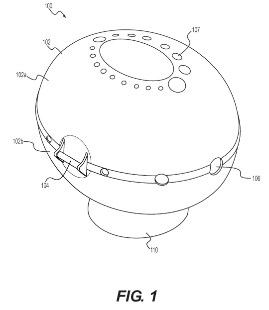
FIG. 1 is a view of an embodiment of a yarn-carrying and dispensing apparatus
FIG. 2 illustrates an insert tray that may be placed inside of the yam-
carrying portion to
separate the yarn-carrying portion in multiple sections for convenience of a
user,
FIGS. 3A and 3B illustrate an embodiment of the yarn-carrying and dispensing
apparatus that includes the insert placed inside the yarn-carrying portion.
FIGS. 4A and 4B illustrate different views of the yarn-carrying and dispensing
apparatus of the current invention.
FIGS. 5A and 5B illustrate the locking mechanism for securing the top and
bottom
portions of the yarn-carrying portion.
FIG. 6 further illustrate needle openings in the yarn-carrying and dispensing
apparatus.
FIG. 7 illustrates a yarn-carrying strap connected to the yarn-carrying
portion.
FIG 8 illustrates a skein and cone tool for more efficiently dispensing yarn
spooled on
skeins, cake, or cone, or similar types of arrangements.
FIG 9 illustrates further view of the skein and cone tool for more efficiently
dispensing
yarn spooled on skeins, cake, cone, or similar types of arrangements.
DETAILED DESCRIPTION
Described herein are embodiments of a yarn-carrying and dispensing apparatus.
The
embodiments described allow knitters to easily transport, carry and use balls
of yarn and other
knitting equipment, such as needles and scissors. The embodiments prevent
balls of yarn from
rolling away or getting tangled or intertwined. The embodiments describe an
apparatus that
easily and smoothly dispenses the yarn, making knitting more efficient and
easier on the go.
With reference to FIG. 1, shown is an embodiment 100 of a yarn-carrying and
dispensing apparatus. The embodiment 100 of the yarn-carrying and dispensing
apparatus
3
CA 03046844 2019-05-24
WO 2018/081302
PCT/US2017/058344
includes a substantially hollow yarn-carrying portion 102. The yarn-carrying
portion 102 in
this embodiment shown is oval shaped. Such a shape accommodates a user to
separate the
yarn-carrying portion into a multiple portions that will allow a knitter to
have more than one
yarn in the yarn-carrying portion 102. Other shaped yarn-carrying portions,
such as spherical
or cylindrical-shaped portions, that can accommodate differently shaped yarn
gatherings such
as yarn rolled on a tube or inverted cone, may be included in the yarn-
carrying and dispensing
apparatus. Alternatively, cubic-shaped, column-shaped or other-shaped yarn
balls may be used
(if flat-bottomed, collar and base portions described below may be omitted).
In the embodiment shown in FIG. 1, the yarn-carrying portion 102 is a hollow
plastic
oval shaped ball of approximately eight (8) inches long and six (6) inches
wide. A variety of
sized yarn-carrying portions may be used, including larger or smaller sized
oval shapes. Plastic
is a useful material for the yarn-carrying portion 102, as it is lightweight
and easily obtainable,
but other materials may be used such as glass, cardboard, or metals. Another
advantage of
plastic is that it may be transparent; accordingly, the embodiment shown is
transparent,
allowing the knitter to see how much yarn is remaining. However, the yarn-
carrying portion
may be opaque or translucent. The yarn-carrying portion 102 is typically
lightweight enough to
be easily carried, e.g., in a purse, bag, or pocket.
The yarn-carrying portion 102 may be subdivided into a top portion 102a and a
bottom
portion 102b. The top portion 102a may include a needle gauge including a
plurality of needle
openings 107, where the diameter of each needle opening 107 corresponds to a
different needle
size. Advantageously, the size of the diameter of each needle opening 107 may
correlate to
various commonly used industry standard needle sizes. For example, the sizes
of each needle
opening 107 may correspond to commonly used needle sizes, such as the
contemporary U.S.
Size, contemporary U.K./U.S. Metric Range, the European Metric Range, or any
other known
needle measuring system. Further, as depicted in FIG. 1, each needle opening
107 may be
arranged along the same line surrounding an upper curvature of the top portion
102a. FIG. 1
shows that the needle openings 107 may be arranged such that each adjacent
needle opening
107 is one size larger or smaller than its neighboring needle opening 107. In
this arrangement,
the largest and smallest needle opening may also be positioned next to one
another. Such an
arrangement is advantageous because it allows a knitter to easily identify a
needle thread size.
With continued reference to FIG. 1, the yarn-carrying portion 102 will
typically have a
hinge 104 that allows the top portion 102a and bottom portion 102b to open and
close, around
the hinge, so that the balls of yarn or other knitting equipment may be placed
inside. The two
portions of the yarn-carrying portion, 102a and 102b, may also be connected
via a joint (a joint
4
CA 03046844 2019-05-24
WO 2018/081302
PCT/US2017/058344
is not shown on FIG. 1, but was illustrated in U.S. Paient No. 8,860,342) The
two portions of
the yarn-carrying portion 102 may also have a "door" or other opening that
allows the yarn to
be placed into the yarn-carrying portion 102.
The yarn-carrying portion 102 shown may also include plurality of yarn-
dispensing
holes or openings 106 for allowing a knitter to dispense yarn. These holes or
openings 106
positioned along the largest circumference of the oval shaped ball, through
which the yarn
exits or dispenses from the yarn-carrying portion 102, as shown. The yarn-
carrying portion 102
may only have one yarn-dispensing hole or opening 106, or a plurality of yarn-
dispensing
holes or opening 106 in different locations other than along the largest
circumference of the
yarn carrying ball, that may enable the yarn to dispense at different angles
and positions from
the yarn-carrying portion 102. The yarn-dispensing holes or openings 106 may
be of large
enough diameter to pass the yarn easily through without significant
resistance.
With continued reference to FIG. 1, the embodiment 100 of the yarn-carrying
and
dispensing apparatus also includes a yarn-carrying collar portion (not shown),
e.g., ball collar.
The yarn-carrying collar portion is typically affixed to a portion of the yarn-
carrying portion
102 (e.g., at the bottom). In the embodiment shown, the yarn-carrying collar
portion serves
multiple functions. The yarn-carrying collar portion provides a mechanism for
connecting the
yarn-carrying portion 102 to a base portion 110. The yarn-carrying collar
portion also provides
a mechanism for connecting the yarn-carrying portion 102 to straps or other
device that enables
the user to easily carry around the yarn-carrying and dispensing apparatus.
With straps (not
shown) attached to the yarn-carrying collar portion, a knitter may knit while
standing with the
yarn-carrying and dispensing apparatus 100 hanging from the knitter's shoulder
and dispensing
yarn.
The yarn-carrying collar portion may include threads, latches or simply be
sized to
snugly fit in the base portion 110 (alternatively, the yarn-carrying portion
102 may connect
directly to the base portion 110, omitting the collar portion). The yarn-
carrying collar portion
may be affixed to the yarn-carrying portion 102 in any of a variety of known
manners.
The yarn-carrying collar portion may also be sized to fit snuggly in standard
or non-
standard drink holders in vehicles, trains, planes, etc. This enables the
knitter to use the yarn-
carrying and dispensing apparatus 100 and knit while traveling on such.
With continued reference to FIG. 1, the embodiment 100 of the yarn-carrying
and
dispensing apparatus shown includes a base portion 110. The base portion 110
is typically
weighted and with a flat bottom so that the yarn-carrying and dispensing
apparatus can easily
and securely sit on a surface, such as a table or a knitters lap. The base
portion 110 is typically
5
CA 03046844 2019-05-24
WO 2018/081302
PCT/US2017/058344
weighted substantially enough to hold the yarn-carrying and dispensing
apparatus in place
when yarn is dispensed from the yarn-carrying portion 102. Accordingly, the
base portion 110
may be made from glass or other such substantially heavy material to hold the
yarn-carrying
and dispensing apparatus in place. Further the base portion 110 may contain
storage space such
that a knitter can store knitting equipment.
The base portion 110 and the ball portion 102 (the yarn-carrying portion) are
typically
designed to easily come apart so that the knitter may travel with just the
yarn-carrying portion
102, or separately carry both.
An insert 200 may be placed within the yarn-carrying portion 102. As depicted
in FIG.
2, the insert 200 is preferably disc-shape and, as will be discussed in
reference to FIG. 3, the
outer edge of the insert 200 may be the same shape and size as the inside of
the bottom portion
102b such that the insert 200 fits snuggly within the bottom portion 102b of
the yarn-carrying
portion 102. A mechanism, such as a latch or hook, may also be installed to
the inner part of
the bottom portion 102b, to secure the insert in place and prevent it from
moving inside of the
yarn-carrying portion 102. Plastic is a useful material for the insert 200, as
it is lightweight and
easily obtainable, but other materials may be used such as glass, cardboard,
or metals.
Preferably the insert includes a plurality of regions (e.g. 202a and 202b in
FIG. 2), each region
may be sized such that a large unused ball of yarn may fit snuggly within each
region. The
outer edges of each region may be elevated. This enables each region to be
bowl shaped, such
that a ball of yarn may naturally sit within it. For example, as depicted in
FIG. 2, along the
edges of the two regions 202a and 202b, the region are elevated. The insert
200 may have any
number of regions to accommodate the needs of the knitter.
As shown on FIG.2, the regions in the insert 200 may be separated by an
elevated wall
204 formed along, the spine, or the boundary between the two regions of the
insert. The
elevated wall may extend higher than the elevated outer edges of each region.
For example, as
depicted in FIG. 2, the insert 200 is separated by elevated wall 204 that
extends higher than the
outer edges of each region. The elevated wall 204 is positioned along the
boundary of the two
regions, region 202a and region 202b. Preferably the elevated wall 204 may
include a ruler
205, or measuring marks, on one or both sides of the elevated wall 204, facing
one or both of
the regions. Such a ruler 205 may display units of measure, such as inches or
centimeters, in
order to advantageously enable quick measuring of yarn or other knitting
materials.
As depicted in FIG. 3A, the insert may fit snuggly within the bottom portion
102b such
a plethora of balls of yarn may be contained within each region, (e.g. 202a
and 202b) within
the yarn-carrying portion 102 on the insert 200. The yarn dispensing holes or
openings 106,
6
CA 03046844 2019-05-24
WO 2018/081302
PCT/US2017/058344
will be positioned such that a yarn may exit or dispense from either region
(202a or 202b)
simultaneously. This configuration afford the knitter greater flexibility.
Additionally, as
shown in FIG. 3A, there may be a cavity 302 beneath the insert 200 and the
bottom portion
102b, as the cavity 302 lies within the yarn carrying portion 102. Such a
cavity 302 may also
be utilized for storing needles or other knitting materials. FIG. 3B
illustrates a yarn-carrying
portion containing an insert, but not any balls of yarn.
FIGS. 4A and 4B illustrate different views of the same embodiment of yarn-
carrying
and dispensing apparatus of the current invention. As shown in FIG. 4A, where
there are no
yarn dispensing holes provided along the joining of the top portion 102a and
the bottom
portion 102b, yarn may be threaded from a ball of yarn sitting on the inside
of the yarn-
carrying portion through the needle openings 107. Needle openings 107 provided
in the top
portion 102a of the yarn-carrying portion is further illustrated in FIG. 6.
Further, needles
which are currently not being used by the knitter may be placed within the
plurality of the need
openings 107, so that the knitter may organize his or her needles with
threading yarn out of the
other openings in the yarn carrying portion. This configuration is
advantageous because the
knitter may organize all of the multiple types of yarn, and needles in one
convenient place
while knitting.
The yarn-carrying top and bottom portions 102a and 102b may be secured to each
other
with a help of a lock system, as is illustrated in FIG. 5A and 5B. Such lock
system enables the
top portion 102A to snap into the bottom portion 102B. The locking apparatus
may be molded,
or inserted into the top and bottom portions. The edge of the bottom portion
102b is indented
in the lock apparatus, so the edge of the top portion 102A can fit within the
indentation if the
two portions are closed together with sufficient pressure. Once the top
portion is locked into
the bottom portion, a protruding region of the bottom portion can be pulled
outward in order to
release the top portion. This enables the top and bottom portion to be
unlocked and for the
yarn carrying portion to be opened as to, for example, allow balls of yarn to
be inserted into the
yarn carrying portion. The lock system may also comprise a latch, hook, or any
other
mechanism capable of securing the yarn-carrying portions 102a and 102b in
place when the
hinge is closed.
FIG. 7 shows a carrying strap 71 which may be connected to the yarn-carrying
portion.
The carrying strap 71 may be composed of plastic, polyester, or any suitable
material. The
strap may connect to groves in the outer surface of the yarn-carrying portion,
and may include
a ruler or measurement markings for making it easier for the knitter to gauge
his or her
measurements when knitting. When the yarn-carrying portion is detached from
the base
7
CA 03046844 2019-05-24
WO 2018/081302
PCT/US2017/058344
portion (110 as shown in Figure 1), the carrying strap 71 enables a knitter to
freely move about
with the yarn-carrying portion.
FIGS. 8 and 9 illustrate different views of a skein and cone tool for more
efficiently
dispensing yarn spooled on skeins, cake, or cone, or similar types of
arrangements, out of the
.. yarn-carrying portion. The skein and cone tool, comprises a rod 81, and
detachable wheels 82
and 83, as shown in FIG. 8. The rod 81, and wheels 82, and 83, may be made of
any suitable
hard material, such as plastic. A skein of yarn, which is a ball of yarn
formed into oblong
shape, may be speared or otherwise pierced by the rod 81. Alternatively or
additionally, a cone
of yarn, which is a long thread of yarn wrapped tightly wrapped around a
conical cardboard
cylinder (or another suitable material) may be speared by the rod 81. Other
configurations of
yarn may be speared on the rod 81, such as a cake, a ball, etc. Spearing, or
otherwise piercing,
the skein, cone, cake, or other configuration of yarn enables the skein, cone,
cake, or other
configuration of yarn to freely rotate about the rod 81.
Once the skein, cone, cake, or other configuration of yarn, has been speared
by rod 81,
the knitter may attach the rod 81 to the wheels 82 and 83. The wheels are
arranged to fit in
between the top and bottom portion of the yarn-carrying portion, such that
when the top and
bottom portion of the yarn-carrying portion are snapped together, as shown in
FIG. 9, the skein
and cone tool sits securely between the top and bottom portion of the yarn-
carrying portion.
The skein and cone tool may advantageously be inserted into the yarn-carrying
portion, in lieu
of the removable insert (i.e. 200 as shown in FIG. 2). The enables the skein,
cone, cake, or
other configuration of yarn, which has been speared by the rod 81 and inserted
into the yarn-
carrying portion, to be freely rotated about the rod 81, so that the knitter
can efficiently
dispense yarn out of the yarn-dispensing holes 106a and 106b, as shown in
Figure 9, while
maintaining the shape of the skein, cone, cake, or other configuration of
yarn. Multiple
skeins or cones, for example, may be simultaneously speared around the rod 81,
with the
thread of each skein or cone arranged to be drawn out of different dispensing
holes 106a and
106b. Further, the yarn dispensing holes 106a and 106b may be different sizes
to
accommodate the different sized threads of yarn for each different skein,
cone, cake, or other
configuration of yarn speared around the rod 81. The skein and cone tool thus
enables the
knitter to efficiently dispense yarn from multiple configurations of yarn
(e.g. multiple skeins,
cones, cakes, etc.) while maintaining the organization of the multiple
configurations of yarn.
Furthermore, the mobile nature of the yarn-carrying portion configured with
the skein or cone
tool provides the mobile knitter with a very organized, flexible, and
adaptable knitting
apparatus.
8
CA 03046844 2019-05-24
WO 2018/081302 PCT/US2017/058344
The terms and descriptions used herein are set forth by way of illustration
only and are
not meant as limitations. Those skilled in the art will recognize that many
variations are
possible within the spirit and scope of the invention.
9