Note : Les descriptions sont présentées dans la langue officielle dans laquelle elles ont été soumises.
Quick-Change Coupler Device and Quick-Change Coupler
System Comprising Said Quick-Change Coupler Device
SCOPE OF THE INVENTION
The present invention relates to a quick-change coupler device for coupling
and uncoupling
implement attachment from construction site equipment. The invention further
relates to a
quick-change coupler system comprising this type of quick-change coupler
device and a
dedicated adapter.
BACKGROUND OF TILE INVENTION
Quick-change coupler devices of this type are used to easily and conveniently
couple and
uncouple different implement attachments to and from construction site
equipment, Using this
type of quick-change coupler device allows, e.g., swivel buckets, claws,
shears, compactors,
magnets, hydraulic hammers or other implement attachments to be coupled to and
uncoupled
from, e.g., a boom of an excavator, in a few seconds and with a high safety
standard from the
operator's cab.
US 6 154 989 A discloses a generic quick-change coupler device. This quick-
change coupler
device comprises a carrier assembly which, on one side, has first receiving
members for
retaining a first coupling member disposed on an implement attachment and, on
the other side,
second receiving members with a locking member, movable between a release
position and a
locking position, for releasably retaining a second coupling member. To
prevent the implement
attachments from falling down, which could potentially endanger people on the
ground if the
locking member were to be unintentionally moved into a release position, a
catch unit with a
hook assembly for retaining a cross bar, which interacts with counter-hooks on
the implement
attachment, is disposed on the carrier assembly. Since the hook assembly
provided for safety
purposes is integrally formed in one piece with the carrier assembly, the
carrier assembly as a
whole will necessarily always be affected as well whenever the hook assembly
is damaged as
a result of improper use. Therefore, to perform a changeover, the quick-change
coupler device
must he positioned especially accurately and carefully.
1
Date recue / Date received 2021-06-10
SUMMARY OF THE INVENTION
The problem to be solved by the present invention is to make available a
compactly designed
quick-change coupler device of the type mentioned above and a quick-change
coupler system
comprising said quick-change coupler device which allow a simplified coupling
maneuver and
ensure increased safety.
This problem is solved by a quick-change coupler device having various
features described
herein, and by a quick-change coupler system having such a quick-change
coupler. Useful
embodiments and advantageous refinements of the invention are further
described.
The catch unit on the quick-change coupler device according to the present
invention comprises
at least one catch hook which is swivel-mounted on the carrier assembly and on
which a control
member for controlling the swivel movement of the catch hook between a folded-
in and a
folded-out position is disposed, said control member being designed to be
actuated by the first
coupling member and actuated independently of the locking unit. Via the
control member, the
implement attachment is able to initiate a movement of the catch hook. No
separate drives are
required. In addition, the control member also ensures that the catch hook can
be moved into
the folded-out position, in which a changeover can be made, only if the
coupling member is
correctly positioned in the catch hook.
In the folded-out position ofthe catch hook, an implement attachment can be
changed by setting
it on the ground, while the catch hook in the folded-in position encloses the
receiving member
for a coupling member. Folding in the catch hook makes for an especially
compact design,
which can markedly reduce the risk of potential collisions with an implement
attachment. If the
locking unit were to be unintentionally released, the foldable catch hook can
catch an implement
attachment by engaging the coupling member on the catch hook in a catch
position and thereby
retain the implement attachment on the quick-change coupler device. The
control I-the swivel
movement of the catch hook takes place independently of the actuation of the
locking unit by a
coupling member on the implement attachment that is to be coupled to the quick-
change coupler
device, No additional control or actuation devices are required. The catch
hook ensures that
even in cases of potential operator error, an implement attachment is reliably
caught. The catch
hook is extremely robust and ensures a high level of safety. Furthermore, a
catch hook damaged
as a result of improper use can easily be replaced without requiring the
replacement of the entire
carrier assembly. There is no need to dismantle or replace the entire carrier
assembly,
2
Date recue / Date received 2021-06-10
According to an especially useful embodiment of the present invention, the
control member can
be designed as an extension piece of the catch hook, which projects in the
direction of the first
receiving member and which has an upper control surface for abutting the
coupling member
which is engaging in the first receiving member. A recess for receiving the
control member can
be disposed on the carrier assembly when the catch hook is in the folded-in
position. However,
the control member can also have a different design.
The catch member can comprise one or a plurality of catch hooks which can be
separated from
or connected to each other, According to an especially useful embodiment, the
catch member
can comprise two catch hooks which are swivel-mounted on the first receiving
members of the
carrier assembly. The catch hooks can be designed as separate and separately
swiveling catch
hooks. However, they can also be connected to each other.
An especially secure retention can be ensured if the catch hook surrounds and
grasps the
coupling member in the form of a semicircle. On its lower face, the catch hook
can have a stop
surface for abutting a front-end abutment surface of the carrier assembly. On
its upper end, the
catch hook can have an abutment surface for abutting a complementary mating
surface of the
carrier assembly.
According to a robust and, from the standpoint of design, favorable
embodiment, the catch hook
can be swivel-mounted about a transverse axis on a connecting strip of the
carrier assembly. `1=0
be able to swivel-mount the catch hook, the connecting strip can have a cross
bore, and the
catch hook can have suitable receiving bores for receiving the transverse
axis.
Expediently, the catch hook can he pivotally mounted on the transverse axis by
means of
mounting bushings. In this manner, the catch hook can be hinged to the carrier
assembly while
ensuring low friction and reliable protection against wear. The transverse
axis can be secured
relative to the carrier assembly by means of a pin to prevent its dropping out
and becoming
twisted.
The present invention further relates to a quick-change coupler system which
comprises a
quick-change coupler device as described above and an adapter which can be
coupled to the
quick-change coupler device.
3
Date recue / Date received 2021-06-10
Accordingly, in one aspect the invention resides in a quick-change coupler
device for coupling
and uncoupling implement attachments to and from construction site equipment,
comprising a
carrier assembly, first receiving members disposed on one side of the carrier
assembly for
receiving a first coupling member, second receiving members disposed on the
other side of the
carrier assembly for receiving a second coupling member, a locking unit
dedicated to the second
receiving members and capable of moving between a release position and a
locking position,
and a catch unit disposed on the carrier assembly [or catching the implement
attachment,
wherein the catch unit comprises at least one catch hook which is swivel-
mounted on the carrier
assembly and on which a control member for controlling the swivel movement of
the catch
hook between a folded-in and a folded-out position is disposed, said control
member being
designed to be actuated by the first coupling member and being actuated
independently of the
locking unit.
BRIEF DESCRIPTION OF THE DRAWINGS
Other features and advantages of the invention will become apparent from the
following
description of a preferred embodiment example with reference to the drawings.
The drawings
show:
3a
Date recue / Date received 2021-06-10
Figure 1 a quick-change coupler system comprising a quick-change coupler
device and
an adapter in a coupling position;
Figure 2 the quick-change coupler system of Figure 1 in a partially
sectioned lateral view;
Figure 3 the quick-change coupler device of Figure 1 with the catch member
in an open
changeover position;
Figure 4 an enlarged view of area A of Figure 1;
Figure 5 an enlarged view of area B of Figure 3;
Figure 6 the quick-change coupler device of Figure 1 with the catch member
in a closed
catch position;
Figure 7 an enlarged view of area C of Figure 6, and
Figure 8 an enlarged exploded detail view of a catch hook.
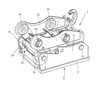
Figure 1 shows a quick-change coupler system for easily and conveniently
coupling and
uncoupling a variety of different implement attachments to and from different
construction site
machines, in particular, excavators, which quick-change coupler system
comprises a quick-
change coupler device 1 and a dedicated adapter 2. Using this type of quick-
change coupler
system allows, e.g., swivel buckets, claws, shears, magnets, compactors,
hydraulic hammers or
other mechanical and/or hydraulic implement attachments to be easily and
conveniently
coupled to and uncoupled from a boom or another implement attachment part of
an excavator
or another construction site vehicle from the operator's cab.
The adapter 2, which can be mounted on an implement attachment, comprises a
base plate 3
and two parallel side walls 4, between which a first bolt-shaped coupling
member 5 and, at a
predefined distance therefrom, a second bolt-shaped coupling member 6 are
disposed for the
detachable connection to the quick-change coupler device 1. The two bolt-
shaped coupling
members 5 and 6 can be inserted into and affixed in complementary bores in the
side walls 4.
CA 3058631 2019-10-11 4
The quick-change coupler device 1, which is also shown in a perspective view
in Figure 3,
comprises a carrier assembly 7 in the form of a welded or cast component
which, on one side,
has rearwardly facing open first receiving members 8 for receiving and
retaining the first bolt-
shaped coupling member 5 and, on the other side, downwardly facing open second
receiving
members 9 for receiving and retaining the second bolt-shaped coupling member
6.
In the embodiment example shown, the quick-change coupler device 1 has two
spaced apart
receiving members 8 for receiving the first coupling member 5 on one side of
the carrier
assembly 7 and, on the other side, two receiving members 9 for receiving the
second coupling
member 6. The rearwardly facing open first receiving members 8 have a claw- or
fork-shaped
configuration. The downwardly facing open second receiving members 9 have a
curved lower
abutment surface 10 against which the second bolt-shaped coupling member 6
abuts. On the
two receiving members 9, a locking unit 11 shown in Figure 2 is disposed for
retaining the
second coupling member 6 in a locking position on the carrier assembly 7. In
the embodiment
shown, the locking unit 11, which can move between a release position and a
locking position,
comprises two bolt-shaped locking members 12 which are movably guided inside
the carrier
assembly 7 and which can be moved by a cylinder between a retracted release
position for
releasing or attaching the adapter 2 or an implement attachment and an
extended locking
position as shown in Figure 2. In the extended locking position, the
downwardly facing open
.. second receiving members 9 are closed on the lower surface by the locking
members 12 which
are movably disposed in the guiding bores in the carrier assembly 7 so that
the second bolt-
shaped coupling member 6 is engaged from below by the bolt-shaped locking
members 12.
On its upper surface, the carrier assembly 7 comprises two parallel side
panels 13 in which
patent openings 14 for mounting bolts (not shown) are disposed for mounting
the quick-change
coupler device 1 on a boom of an excavator or an implement attachment part of
another
construction site vehicle.
To attach an implement attachment by means of the quick-change coupler device
1, the quick-
change coupler device 1, which, as a rule, is disposed on a boom of an
excavator, is first moved
such that the first coupling member 5, which is disposed on the adapter 2 or
directly on the
implement attachment, is retracted into the claw- or fork-shaped receiving
members 8 on one
side of the quick-change coupler device 1. Next, the quick-change coupler
device 1, with the
locking members 12 still in the retracted position, is swiveled about the
first bolt-shaped
CA 3058631 2019-10-11 5
coupling member 5 so that the second coupling member 6 on the adapter or
implement
attachment comes to abut the abutment surfaces 10 of the downwardly facing
open receiving
members 9 on the other side of the quick-change coupler device 1.
Subsequently, the locking
members 12, which are movably disposed in guiding bores in the carrier
assembly 7 of the
quick-change coupler device 1, can be hydraulically extended so that the
second bolt-shaped
coupling member 6 is engaged from below by the two locking members 12 on the
quick-change
coupler device 1 and the implement attachment is thereby retained on the quick-
change coupler
device 1.
To prevent an implement attachment that is coupled to the quick-change coupler
device 1 from
coming detached from the quick-change coupler device as a result of an
unintentional release
of the locking member caused by an operator error or malfunctions and from
subsequently
possibly dropping off while the quick-change coupler device is in a lifted
position, a catch unit
is additionally disposed on the carrier assembly 2 [sic; adapter 2]. The catch
unit 15 is
15 designed to surround and grasp the coupling member 5 which is disposed
on the adapter 2 or
the implement attachment and which engages in the first receiving members 8.
The catch unit
15 is designed such that in the event that an implement attachment is
unintentionally released
from the coupling position, said implement attachment, as a result of the
coupling member
being engaged in the catch hook arrangement, is caught in a catch position and
thereby retained
on the quick-change coupler device.
In the embodiment shown, the catch unit 15 comprises two separate catch hooks
16 which are
not rigidly disposed on the carrier assembly 2 [sic] of the quick-change
coupler device 1, but
instead are swivelably hinged about a transverse axis 17 on the carrier
assembly 1 [sic] by
means of a type of hinge. The two catch hooks 16 are disposed on the two
posterior receiving
members 8 and configured such that they surround and grasp a coupling member 5
on the
adapter 2 or on an implement attachment and, in the event that the quick-
change coupler device
1 is unintentionally released, are able to catch the implement attachment by
causing the
coupling member 5 to engage the catch hook 16 in a catch position. The
swiveling configuration
allows the catch hooks 16 to move between a folded-out position as shown in
Figures 3 and 5
and a folded-in position as shown in Figures 6 and 7.
As especially well illustrated in Figure 8, the carrier assembly 7 had
rearwardly projecting
connecting strips 18 with a patent cross bore 19 for connecting the catch
hooks 16. The
CA 3058631 2019-10-11 6
rearwardly projecting connecting strips 18 disposed on the carrier assembly 7
below the
receiving members 8 jut out into a gap 20 between two legs 21 of the catch
hook 14 [sic; 16]
which project forwardly in the direction of the carrier assembly 7. Disposed
in the two legs 21
of the catch hook 14 [sic] are receiving bores 22 which are aligned with each
other and which,
in the mounted position of the catch hook 16, are coaxial with the cross bore
19 in the
connecting strip 18. The horizontal transverse axis 17 is inserted into the
cross bore 19 of the
connecting strip 18 and secured by means of a pin 23 to prevent its falling
out and becoming
twisted.
Furthermore, as especially well illustrated in Figures 5 and 8, a control
member 24 designed to
be actuated by the first coupling member 5 is disposed on the catch hook 16.
Via the control
member 24, the catch hook 16, on engagement in the receiving member 8, can be
moved by the
coupling member 5 from the folded-out position shown in Figures 3 and 5 into
the folded-in
position shown in Figures 1 and 2. In addition, the control member 24 also
ensures that the
catch hook 16 can be moved into the folded-out position, in which a changeover
can be made,
only if the coupling member 5 is correctly positioned in the catch hook 16. In
the embodiment
shown, the control member 24 is configured in the form of an extension piece
projecting in the
direction of the first receiving member 8, with the control member having a
control surface 25
which, in the folded-in position of the catch hook 16, is flush with the
inside contour of the
receiving member 8 and, in the folded-out position of the catch hook 16,
projects inwardly
relative to the inside contour of the receiving member 8. Disposed on the
carrier assembly 7 is
a lateral recess 26 for receiving the control member 25 when the catch hook 16
is in the folded-
in position.
The catch hook 16 is configured such that it surrounds and grasps the coupling
member 5 in the
form of a semicircle over an angle of approximately 180 . This ensures an
especially secure
hold in any position of the quick-change coupler device 1. In the folded-in
position of the catch
hook 16, the receiving member 8 is rearwardly completely enclosed by the catch
hook 16. In
this folded-in position, the catch hook 16 also does not project particularly
far out relative to
the carrier assembly 7 so that the design is compact and the risk of potential
collisions with an
implement attachment is markedly reduced. Even if the coupling member 5 were
to detach itself
from the receiving member 8 and become caught by the catch hook 16, a secure
hold would be
ensured by the shape of the catch hook 16.
CA 3058631 2019-10-11 7
õ
As Figure 7 indicates, on its lower surface, the catch hook 16 has a stop
surface 27 for abutting
a front-end abutment surface 28 of the carrier assembly 7 below the receiving
member 8. In its
downwardly swiveled folded-out position, the stop surface 27 of the catch hook
16 abuts the
abutment surface 28 of the carrier assembly 7 so that the catch hook 16 is
retained in this lower
catch position. On its upper end, the catch hook has an abutment surface 29
which in the
upwardly swiveled folded-in position of the catch hook 16 comes to abut a
complementary
mating surface 30 of the carrier assembly 7.
The catch member 15 described above serves as an additional safety mechanism,
by mean of
which an implement attachment can be securely caught and retained even if the
lock is
unintentionally released. The catch unit 15 is independent of, and not
connected to, the locking
unit 11.
CA 3058631 2019-10-11 8
List of reference characters
1 Quick-change coupler
2 Adapter
3 Base plate
4 Side wall
First coupling member
6 Second coupling member
7 Carrier assembly
8 First receiving member
9 Second receiving member
Abutment surface
11 Locking unit
12 Locking member
13 Side panel
14 Opening
Catch unit
16 Catch hook
17 Transverse axis
18 Connecting strip
19 Cross bore
Gap
21 Leg
22 Receiving bore
23 Pin
24 Control member
Control surface
26 Recess
27 Lower stop surface
28 Abutment surface
29 Upper stop surface
Mating surface
CA 3058631 2019-10-11 9