Note : Les descriptions sont présentées dans la langue officielle dans laquelle elles ont été soumises.
CA 03068568 2019-12-27
WO 2019/008214 PCT/F12017/050502
1
A FROTH FLOTATION ARRANGEMENT AND A FROTH FLOTATION METHOD
FIELD OF THE INVENTION
[0001] The invention relates to a froth flotation arrangement and a
froth flotation method, and particularly to an arrangement and a method coin-
s prising a primary line comprising at least three flotation cells
connected in series.
BACKGROUND OF THE INVENTION
[0002] A froth flotation arrangement is used for treating mineral ore
particles suspended in slurry.
BRIEF DESCRIPTION OF THE INVENTION
[0003] An object of the present invention is to provide a froth flota-
tion arrangement and a method for treating mineral ore particles suspended in
slurry. The objects of the invention are achieved by a method and an
arrangement
which are characterized by what is stated in the independent claims. The pre-
ferred embodiments of the invention are disclosed in the dependent claims.
[0004] The invention is based on an arrangement for treating mineral
ore particles suspended in slurry, comprising a flotation cell for separating
the
slurry into an underflow and an overflow. The arrangement comprises
- a primary line comprising at least three flotation cells connected in
series, wherein each subsequent flotation cell is arranged to receive the
under-
flow from the previous flotation cell,
- the flotation cell comprising a tank, and the flotation cell comprising
an impeller within the tank, and
- the flotation cell comprising g a gas supply within the tank,
- the tank has a volume of at least 200 m3,
- the flotation cell comprising a froth collection launder capable to re-
ceive the overflow,
- the froth collection launder comprising a froth overflow lip,
- the flotation cell having an available froth surface area,
- the flotation cell having a pulp area, where the pulp area is calculated
as an average from the cross sectional areas of the tank at the height of the
impel-
ler,
- a ratio between a height from a bottom of the tank to the froth over-
flow lip of the froth collection launder and the diameter of the tank at the
height
of the impeller of a pulp area is less than 1,5,
CA 03068568 2019-12-27
WO 2019/008214 PCT/F12017/050502
2
-the third flotation cell or subsequent flotation cell in the series has a
ratio between an available froth surface area and the pulp area (A froth/A
pulp) is
less than 0,45..
[0005] The invention is based on a froth flotation method for treating
mineral ore particles suspended in slurry, and in the method separating the
slurry
in a flotation cell into an underflow and an overflow, the method comprising
the
steps of:
¨ connecting at least three flotation cells in series for creating a
primary line,
- feeding the slurry to a tank of the flotation cell,
¨ wherein each subsequent flotation cell is receiving the under-
flow from the previous flotation cell,
¨ introducing gas into the tank through a gas supply,
¨ mixing the slurry and the gas with an impeller within the tank,
- providing the tank with a volume of at least 200 m3,
¨ receiving the overflow in a froth collection launder provided in
the flotation cell,
¨ receiving the overflow over a froth overflow lip provided in
the froth collection launder,
- forming an available froth surface area in the flotation cell,
¨ the flotation cell having a pulp area, where the pulp area is cal-
culated as an average from the cross sectional areas of the tank
at the height of the impeller,
¨ providing the tank with a ratio between a height from a bottom
of the tank to the froth overflow lip of the froth collection laun-
der and the diameter of the tank at the height of the impeller
of a pulp area being less than 1,5,
¨ feeding the underflow to the third flotation cell or subsequent
flotation cell in the series wherein a ratio between an available
froth surface area and the pulp area comprises less than 0,45.
[0006] An effect of the method and arrangement of the invention is
that reduced available froth area on the top of the tank leads to a good froth
re-
covery since the transport distance of the fragile bubble particle aggregate
to a
froth collection launder is reduced. Further, the reduced horizontal transport
dis-
tance takes more relevance for the recovery of coarse particles.
CA 03068568 2019-12-27
WO 2019/008214 PCT/F12017/050502
3
BRIEF DESCRIPTION OF THE DRAWINGS
[0007] In the following the invention will be described in greater de-
tail by means of preferred embodiments with reference to the accompanying
drawings, in which
Figure 1 shows a top view of a froth flotation arrangement;
Figure 2 shows a side view of the arrangement shown in Figure 1;
Figure 3 shows a perspective view of two froth collection launders;
Figure 4 shows a top view of a froth flotation arrangement;
Figure 5 shows a side view of a froth flotation arrangement;
Figure 6 shows a top view of a froth flotation arrangement;
Figure 7 shows a side view of a froth flotation arrangement;
Figure 8 shows a primary line in a froth flotation arrangement.
DETAILED DESCRIPTION OF THE INVENTION
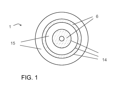
[0008] Figure 1 shows a top view of a froth flotation arrangement for
treating mineral ore particles suspended in slurry. Figure 2 shows a side view
of
the arrangement shown in Figure 1. The froth flotation arrangement comprises a
flotation cell 1 which separates the slurry 2 into an underflow 3 and an
overflow
4.
[0009] Froth flotation is a physical separation method for separating
particles based on differences in the ability of air bubbles to selectively
adhere to
specific mineral surfaces in a mineral/water slurry. If a mixture of
hydrophobic
and hydrophilic particles are suspended in water, and air is bubbled through
the
suspension, then the hydrophobic particles will tend to attach to the air
bubbles.
[0010] The tank 5 of the flotation cell 1 contains slurry 2 which is a
mixture of solid particles in a carrier liquid, e.g. mineral particles in
water. The
bubble¨particle aggregates move up in the froth flotation cell 1 by buoyancy
forming a froth 6 layer on the surface. The froth 6 comprises water, bubbles
and
particles.
[0011] The tank 5 is mechanically agitated. The tank 5 comprises an
impeller 7 within the tank 5 and a gas supply 8. The agitator 9 disperses air
in the
slurry 2, pumps slurry 2, keeps solids in the suspension and provides an envi-
ronment in the cell tank 5 for interaction of bubbles and hydrophobic
particles
and their subsequent attachment and therefore separation of valuable mineral
particles from the undesired gangue mineral particles. The agitator 9
comprises
an impeller 7 and a drive assembly for rotating the impeller 7. Further, the
agita-
CA 03068568 2019-12-27
WO 2019/008214 PCT/F12017/050502
4
tor 9 may also comprise a stator 10 for providing a more stable air
dispersion.
The drive assembly may comprise a motor 11 and a drive shaft 12.
[0012] A gas supply 8 to the froth flotation cell 1 comprises pressur-
ized or self-aspirating gas supply. Examples of pressurized gas supply systems
are
pipes or tubes delivering gas to the bottom part of the tank 5 at least partly
under
the impeller 7. Gas may be supplied to the impeller 7 area also through
conduits
formed to the agitator 9 comprising the impeller 7.
[0013] The tank 5 volume is preferably large and comprises at least
200 m3. The tank 5 volume comprises the volume of the tank 5 surrounding the
slurry 2 measured from the bottom 13 of the tank 5 to height h2 of a froth
over-
flow lip 14 of the froth collection launder 15. The tank 5 may comprise
smaller
cylindrical containers within it. Large tank 5 volumes have benefits such as
lower
capital, operating and maintenance costs.
[0014] The tank 5 further comprises a froth collection launder 15
comprising a froth overflow lip 14. The froth collection launder 15 is capable
to
receive the overflow 4. Figure 3 shows a perspective view of two froth
collection
launders 15. The froth collection launder 15 collects the froth 6 from the
surface,
i.e. the overflow 4, and transports it out of the tank 5 of the froth
flotation cell 1.
The froth collection launder 15 is an inclined drainage module. The froth 6
layer
level is generally above the froth overflow lip 14 of the launder 15
permitting the
froth 6 to flow over the overflow lip 14. The froth collection launder 15
comprises
a subsurface discharge pipe 16 for carrying the froth 6 or concentrate
product, i.e.
the overflow 4, from the launder 15 to outside of the tank 5, for instance.
[0015] The froth flotation cell 1 can have one or more froth collection
launders 15 which can be either internal or external, double, radial,
depending on
the capacity of the froth collection launder 15 necessary for the froth 6
removal.
An internal launder means a froth collection launder 15 which is positioned at
least partially above the pulp area A pulp.
[0016] In the arrangement in the froth flotation cell 1 the ratio be-
.. tween an available froth surface area and the pulp area A froth/A pulp is
less than
0,45, where the pulp area A pulp is calculated as an average from the cross
section-
al areas of the tank 5 at the height of the impeller h1. The available froth
surface
area A froth is the horizontal area at the top of the tank 5 which is open for
the
froth 6 to flow at the height h of the lip 14 of the froth collection launder
15. The
available froth surface area A froth is the dashed froth 6 areas shown in
Figure 1,
Figure 4 and Figure 6. This reduced available froth surface area Afroth on the
top of
CA 03068568 2019-12-27
WO 2019/008214 PCT/F12017/050502
the tank 5 shortens the transport distance of the fragile bubble particle
aggregate
to a froth collection launder or launders 15. Solid particles are an important
com-
ponent of the froth 6 structure and adequate solid particles will also lead to
a high
froth 6 stability and a better transportation of the froth 6 to the launder
lip. A bet-
s ter
particle recovery is then obtained and especially with coarse particles. Addi-
tionally, the reduced available froth surface area A froth Stabilizes the
froth 6 by
creating a thicker froth 6 layer as a flotation cell 1 with a high froth
surface area
could lead to a situation where insufficient material with solid particles is
present
to stabilize the froth 6.
[0017] The ratio between a height h from a bottom 13 of the tank 5 to
the lip 14 of the froth collection launder 15 and the diameter D of the tank 5
at the
height of the impeller h/D is less than 1,5. This means the tank 5 is
relatively
shallow.
[0018] The third flotation cell 1or subsequent flotation cell 1 in the
series of connected flotation cells 1 has a ratio between the available froth
surface
area and the pulp area A froth/A pulp less than 0,45.
[0019] The arrangement provides a high concentrate content to the
overflow 4 of the flotation cell 1 even when the slurry 2 fed to the flotation
cell 1
is diluted, i.e. the flotation cell 1 receives an underflow 4 resulting from a
multiple
of previous flotation cells 1. A shallow tank 5 having a relatively large pulp
area A
pulp provides a long residence time for the particles in the slurry 2 to meet
air
bubbles and create air bubble particle aggregates. The significance of the
resi-
dence time increases with decreasing concentrate content of the inlet slurry
2.
The reduced available froth surface area A froth creats a thicker froth 6
layer and
results in a more pure froth 6.In an embodiment the ratio between a height h
from a bottom of the tank 13 to the froth overflow lip 14 of the froth
collection
launder 15 and the diameter D of the tank h/D is less than 1,1. This means the
tank 5 is shallow.
[0020] In an embodiment the ratio between the available froth sur-
face area and the pulp area A froth/A pulp is from 0,1 to 0,45. The decrease
in the
available surface area A froth for the froth 6 to flow causes the rising
particles to
flow also in a horizontal direction. In order to keep the froth 6 layer
stabile the
ratio is preferably not below the lower limit.
[0021] The periphery shape of the froth collection launder 15 shape
may correspond the tank 5 periphery shape. The shape of the froth collection
launder 15 may be circular or rectangular, for instance.
CA 03068568 2019-12-27
WO 2019/008214 PCT/F12017/050502
6
[0022] The reduction of the available froth surface area A froth is pref-
erably made at the periphery of the tank 5. This is advantageous as in the
middle
of the tank 5 are more gas bubbles than in the periphery. The reduction of the
available froth surface area A froth can be implemented by means of an
internal
peripheral launder 15, or a froth blocker 17, for instance. An internal
peripheral
type of a froth collection launder 15 extends around the inside top of the
sidewall
of the tank 5 as shown in Fig.4.
[0023] If the tank 5 comprises either an internal peripheral launder
or a peripheral froth blocker 17, the available froth surface area A froth may
be
10 defined
by subtracting a launder area A launder which is the area covered by froth
collection launders 15 at the height h2 of the froth overflow lip 14, and a
blocker
area which is the area not available for the froth 6 and not covered by the
froth
collection launders 15 at the height h2 of the lip 14 of the froth collection
launder
15 from the pulp area A pulp.
15 [0024]
As an example, the ratio between the area of the internal pe-
ripheral launder and the pulp area A int launder/A pulp, or the ratio between
the area
of the peripheral froth blocker and the pulp area A mocker/A pulp, is more
than 0,1,
preferably more than 0,1 and less than 0,5. The angle of ascent for the air
bubble
particle aggregates limits the amount of the froth surface area which can be
re-
duced. If the angle of descent becomes too low-gradient the air bubble
particle
aggregates start forming air pockets causing the particles to drop back.
[0025] In an embodiment the tank 5 is circular in cross section at the
froth overflow lip height h2 of the tank 5 as shown in Fig.2. Further, the
froth col-
lection launders 15 are circular shaped and positioned coaxially as shown in
Fig-
ure 1. A circular tank 5 provides a more stable air bubble dispersion causing
a
more stable froth layer as the impeller 7 is positioned in the middle of the
tank 5
producing a circular shaped air bubble zone.
[0026] Figure 3 presents an embodiment comprising two froth collec-
tion launders 15, and the first launder 15 is arranged within the second
launder
15 at a distance apart d1. The froth collection launders 15 comprise circular
pe-
ripheries.
[0027] The average froth transport distance dtr is preferably less than
100 cm and more than 5 cm with circular shaped and coaxially positioned froth
collection launders 15. The average froth transport distance dtr is the
distance the
froth 6 has to travel in horizontal direction before reaching the froth
overflow lip
14. The average froth distance dtr is calculated as a ratio between the sum of
the
CA 03068568 2019-12-27
WO 2019/008214 PCT/F12017/050502
7
transport distances between the froth collection launders 15 and the number of
the froth collection launders 15 (di-Fd2+...d)/n. If two launders 15 have
overflow
lips 14 facing each other the transport distance is half of the distance
between the
two launders 15, e.g. half of the distance between the froth overflow lips 14.
When two launders 15 have an overflow lip 14 and a launder side wall facing
each
other the transport distance is the distance between the two launders 15, e.g.
the
distance between the froth overflow lip 14 and the side wall.
[0028] If the average froth transport distance dt, is too long some par-
ticles of the air bubble agglomerates may detach and flow downwards. This
froth
in drop back reduces the froth recovery to the froth collection launders
15.
[0029] The tank 5 may comprise at least three separate froth collec-
tion launders 15, and the number of froth overflow lips 14 in the froth
collection
lounders 15 is five as shown in Figure 5. The outer froth collection launder
15
comprises an internal peripheral launder with one froth overflow lip 14. The
oth-
er two internal froth collection launders 15 comprise two froth overflow lips
14
each. This arrangement reduces the drop back of the air bubble particle agglom-
erates as the transport distance to a froth collection launder 15 is shorter
com-
pared to a case where there is only one froth collection lauder 15.
[0030] Figure 7 shows an embodiment where the froth flotation cell 1
comprises two froth collection launders 15 and a froth blocker 17, a cone
blocker
in the middle of the tank 5. The available froth surface area A froth is
further re-
duced with a peripheral froth blocker 17. The outer froth collection launder
15
has two froth overflow lips 14. The inner froth collection launder 15 has one
froth
overflow lip 14 facing the froth blocker 17.
[0031] In another embodiment the froth collection launders 15 are
positioned in radial direction r of the tank 5 as shown in Figure 6.
[0032] The average froth transport distance dtr is preferably less than
100 cm and more than 5 cm with froth collection launders 15 positioned in
radial
direction r of the tank 5. The average froth distance is calculated as a ratio
be-
tween the sum of the transport distances between the froth collection launders
15 and the number of the froth collection launders (di-Fd2+...d)/n. The
transport
distance between two launders 15 having overflow lips 14 facing each other is
half of the distance between the two launders. The transport distance between
two launders 15 having an overflow lip 14 and a launder side wall facing each
other is the distance between the two launders. The distance between two laun-
ders 15 is an average of the distances between the first ends and the second
ends
CA 03068568 2019-12-27
WO 2019/008214 PCT/F12017/050502
8
of the two radially directed r launders 15.
[0033] Further, in an embodiment comprising froth collection laun-
ders 15 in a peripheral direction of the tank 5 a ratio between the average
transport distance dt, and a froth collection launder 15 average width in
radial
direction dtr/w is 0,1-0,6. This ratio provides adequate size for the froth
collec-
tion launder 15 to receive the flowing froth 6 overflow. If the froth
collection
launder 15 is too narrow compared to the amount of the overflowing froth 6 the
transporting capacity of the launder is exceeded and the launder is clogged
15. In
Figure 3 the average transport distance dtr is di/2.
[0034] In a froth flotation method for mineral ore particles suspended
in slurry 2 are treated. In the method the slurry 2 in a flotation cell 1 is
separated
into an underflow 3 and an overflow 4. The method comprises the steps of: con-
necting at least three flotation cells 1 in series for creating a primary line
18, feed-
ing the slurry 2 to a tank 5 of the flotation cell 1, wherein each subsequent
flota-
tion cell 1 is receiving the underflow 3 from the previous flotation cell 1,
introduc-
ing gas into the tank 5 through a gas supply 8, mixing the slurry 2 and the
gas
with an impeller 8 within the tank 5, providing the tank 5 with a volume of at
least 200 m3, receiving the overflow 4 in a froth collection launder 15
provided in
the flotation cell 1, receiving the overflow 4 over a froth overflow lip 14
provided
in the froth collection launder 15, forming an available froth surface area A
froth in
the flotation cell 1, the
flotation cell 1 having a pulp area A pulp, where the
pulp area A pulp is calculated as an average from the cross sectional areas of
the
tank 5 at the height h1 of the impeller 8, providing the tank 5 with a ratio
between
a height h from a bottom 13 of the tank 5 to the froth overflow lip 14 of the
froth
collection launder 15 and the diameter D of the tank Sat the height h1 of the
im-
peller 8 of a pulp area h/D being less than 1,5, feeding the underflow 3 to
the
third flotation cell 1 or subsequent flotation cell 1 in the series wherein a
ratio
between an available froth surface area and the pulp area A froth/A pulp com-
prises less than 0,45.
[0035] Further, in the froth flotation method the ratio between a
height h from a bottom 13 of the tank 5 to the froth overflow lip 14 of a
froth col-
lection launder 15 and the diameter D of the tank is less than 1,1, for
instance.
[0036] Figure 8 shows a primary line 18 in a froth flotation arrange-
ment. The primary line 18 comprises at least three flotation cells 1 connected
in
series as shown in Fig.8. Each flotation cell 1 separates the slurry 2 into an
under-
flow 3 and an overflow 4. Each subsequent flotation cell 1 is arranged to
receive
CA 03068568 2019-12-27
WO 2019/008214 PCT/F12017/050502
9
the underflow 3 from the previous flotation cell 1.
[0037] The presented arrangement and method are suitable for a
slurry 2 comprising copper (Cu), for instance. The slurry 2 fed to the third
flota-
tion cell 1 or subsequent cell in the series may comprise copper (Cu) less
than 0,2
weight %.
[0038] It will be obvious to a person skilled in the art that, as the
technology advances, the inventive concept can be implemented in various ways.
The invention and its embodiments are not limited to the examples described
above but may vary within the scope of the claims.
[0039] Part list: 1 a flotation cell; 2 slurry, 3 an underflow; 4 an over-
flow; 5 a tank; 6 a froth; 7 an impeller; 8 a gas supply; 9 an agitator; 10 a
stator;
11 a motor; 12 a drive shaft; 13 a bottom; 14 an overflow lip; 15 a froth
collection
launder; 16 a discharge pipe; 17 a froth blocker; 18 a primary line.
[0040] A blocker a blocker area; A int blocker an internal blocker area; A
launder a launder area; A int launder a lauder area; A froth a froth surface
area; A pulp a
pulp area; d1, d2,...du a distance; dtr a transport distance; D a diameter; h
a height;
h1 a height of the impeller; h2 a height; r a radial direction.