Note : Les descriptions sont présentées dans la langue officielle dans laquelle elles ont été soumises.
CONDUIT LOCKING SYSTEM FOR AN APPLIANCE
RELATED APPLICATIONS
This application claims priority to U.S. Provisional Patent Application No.
62/807295,
filed February 19, 2019, the entirety of which is hereby incorporated herein
by reference.
BACKGROUND
Traditional appliance exhaust venting systems are utilized to remove exhaust
gas from a
home or building. In the heating and cooling industry, many sections of
conduit must be joined
together to route the exhaust gas from the appliance within the house or
building to the roof or
other exterior surface. Joining these sections of conduit together can be
burdensome for an
installer, and it is often difficult to safely and securely connect the
sections of conduit together.
With the recent development of high efficiency appliances, there is a need to
have positive
pressure venting systems safely and efficiently vent exhaust gas. Some of the
connections currently
used in exhaust venting systems are difficult to manipulate to make secure
connections.
Additionally, a significant amount of conduit may be wasted because of the
requirement that
specific male and female connectors be used with one another in current
exhaust venting systems.
As such, there is a need for an efficient, safe, and easily manipulated
conduit locking system.
SUMMARY
The present disclosure relates generally to a conduit locking system for
appliance exhaust.
One exemplary configuration of the conduit locking system for appliance
exhaust includes a first
cylindrical conduit having an inner surface and an outer surface. The first
cylindrical conduit
includes a male portion having an outer diameter. The conduit locking system
also includes a
second cylindrical conduit having an inner surface and an outer surface. The
second cylindrical
conduit also has a female portion including an engagement protrusion radially
disposed on the
CA 3072832 2020-02-18
outer surface. The female portion has an inner diameter configured to engage
the outer diameter
of the male portion of the first cylindrical conduit to define a continuous
fluid passageway
therethrough. The conduit locking system further includes a conduit locking
band. The conduit
locking band includes an annular band having a tensioner configured to engage
the male portion
of the first cylindrical conduit. The conduit locking band also includes a
locking arrangement
coupled to the annular band and comprises a plurality of fingers that are
disposed radially about
the annular band. The plurality of fingers are configured to engage the
engagement protrusion of
the female portion of the second cylindrical conduit. The conduit locking band
is moveable from
a clamped position to an undamped position. The clamped position has a
circumference less than
the circumference of the unclamped position.
One exemplary method for securing a first cylindrical conduit to a second
cylindrical
conduit includes the step of providing a first cylindrical conduit having a
male portion having an
outer diameter. The method also includes the step of providing a second
cylindrical conduit having
a female portion including an engagement protrusion extending radially outward
and having an
inner diameter. The inner diameter of the female portion of the second
cylindrical conduit is greater
than the outer diameter of the male portion of the first cylindrical conduit.
The engagement
protrusion defines a circumferential channel on an inner surface of the female
portion of the second
cylindrical conduit. The method additionally comprises the step of providing a
conduit locking
band comprising an annular band having a tensioner and a locking arrangement.
The locking
arrangement is coupled to the annular band and includes a plurality of
fingers. The plurality of
fingers are configured to engage the female portion of the second cylindrical
conduit. The method
further includes the step of engaging the plurality of fingers with the
engagement protrusion on
the outer surface of the female portion of the second cylindrical conduit to
the conduit locking
2
CA 3072832 2020-02-18
band. The method also comprises the step of engaging the male and female
portions of the first
and second cylindrical conduits through the conduit locking band such that the
plurality of fingers
remain engaged with the engagement protrusion on the female portion and such
that the conduit
locking band is disposed in an unclamped position about the outer diameter of
the male portion of
the first cylindrical conduit, whereby the male and female portions engage to
define a continuous
fluid passageway and the conduit locking band is positioned for clamping. The
method
additionally includes the step of applying a force to move the conduit locking
band from the
unclamped position to a clamped position thereby releasably locking the first
cylindrical conduit
to the second cylindrical conduit.
These and other configurations, features, and advantages of the present
disclosure will be
apparent to those skilled in the art. The present disclosure is not to be
limited to or by these
configurations, features, and advantages.
BRIEF DESCRIPTION OF THE DRAWINGS
Advantages of the present disclosure will be readily appreciated as the same
becomes better
understood by reference to the following detailed description when considered
in connection with
the accompanying drawings.
Figure 1 is a perspective view of a conduit locking system including a first
cylindrical
conduit, a second cylindrical conduit, and a conduit locking band.
Figure 2 is a perspective view of the first cylindrical conduit including a
male portion.
Figure 3 is a perspective view of the second cylindrical conduit including a
female portion.
Figure 4 is cross-sectional view of the conduit locking system taken along
line 4-4 of Figure
1.
3
CA 3072832 2020-02-18
Figure 5A is a perspective view of the conduit locking band in an unclamped
position, with
the conduit locking band including an annular band and a locking arrangement.
Figure 5B is a perspective view of the conduit locking band in a clamped
position.
Figure 6 is a sectional view of the conduit locking band taken along line 6-6
of Figure 5A.
Figure 7 is a sectional view of one of the locking arrangements including a
plurality of
fingers.
Figure 8A is a perspective view of the annular band being pre-formed.
Figure 8B is a perspective view of the locking arrangement being pre-formed. .
Figure 8C is a perspective view of the locking arrangement being formed.
Figure 9 is a perspective view of a formed conduit locking band.
Figure 10A is a perspective view of the male portion of the first cylindrical
conduit, the
female portion of the second cylindrical conduit, and the conduit locking
band.
Figure 10B is a cross-sectional view of the male portion of the first
cylindrical conduit
engaging the conduit locking band and the female portion of the second
cylindrical conduit.
Figure 10C is a cross-sectional view of the male portion of the first
cylindrical conduit
engaging the female portion of the second cylindrical conduit and the conduit
locking band.
Figure 10D is a perspective view of the conduit locking system with the
conduit locking
band in the unclamped position.
Figure 10E is a perspective view of the conduit locking system with the
conduit locking
band in the clamped position.
Figure 1OF is a cross-sectional view of the conduit locking system with the
conduit locking
band in the clamped position.
4
CA 3072832 2020-02-18
Figure 1 1A is a cross-sectional view of the conduit locking system with a
rectangular
shaped outer surface of the engagement protrusion of the female portion of the
second cylindrical
conduit.
Figure 11B is a cross-sectional view of the conduit locking system with a
triangular shaped
outer surface of the engagement protrusion of the female portion of the second
cylindrical conduit.
Figure 11C is a cross-sectional view of the conduit locking system with a
trapezoidal
shaped outer surface of the engagement protrusion of the female portion of the
second cylindrical
conduit.
Figure 11D is a cross-sectional view of the conduit locking system with an
ovoidal shaped
outer surface of the engagement protrusion of the female portion of the second
cylindrical conduit.
Figure 11E is a cross-sectional view of the conduit locking system with a
circular shaped
outer surface of the engagement protrusion of the female portion of the second
cylindrical conduit.
DETAILED DESCRIPTION
As the heating and cooling industry strives to make appliances more energy
efficient, new
appliances require a positive pressure venting system. Positive pressure
venting systems require
robust venting systems utilizing a conduit coupling system that securely and
safely joins two pieces
of conduit together. Additionally, a conduit coupling system that can
releasably couple and
uncouple sections of conduit to one another makes installation of venting
systems easier.
One example of a conduit coupling system for defining an appliance exhaust
that may be
utilized to secure and safely join adjacent sections of conduit may comprise a
conduit locking
system. Generally, two or more sections of conduit may be joined together to
vent exhaust from
the source at an appliance to the exterior of a home or building.
CA 3072832 2020-02-18
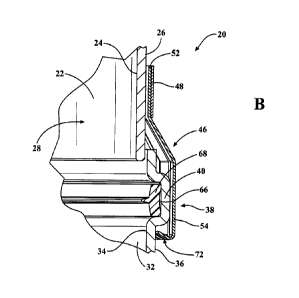
Figure 1 illustrates a conduit locking system 20 for coupling a first
cylindrical conduit 22
to a second cylindrical conduit 32 to route exhaust from an appliance to an
exterior environment.
The first cylindrical conduit 22 having an inner surface 24 and an outer
surface 26. The first
cylindrical conduit 22 may also comprise a first end 27 and an opposing second
end 25. The first
end may 27 may comprise a male portion 28 having an outer diameter 30.
The conduit locking system 20 further comprises a second cylindrical conduit
32 having
an inner surface 34 and an outer surface 36. The second cylindrical conduit 32
may also comprise
a first end 37 and an opposing second end 35. The second end 35 may comprise a
female portion
38 having an engagement protrusion 40 radially disposed on the outer surface
36. The female
portion 38 may comprise an inner diameter 42 configured to engage the outer
diameter 30 of the
male portion 28 of the first cylindrical conduit 22 to define a continuous
fluid passageway 44. The
continuous fluid passageway 44 allows fluid, such as an exhaust gas, to flow
between the first
cylindrical conduit 22 and the second cylindrical conduit 32 or vice versa.
While not illustrated in the Figures, it is contemplated that the first
cylindrical conduit 22
may comprise a female portion disposed at the second end 25 to allow for
coupling of an additional
cylindrical conduit to the first cylindrical conduit 22 opposite the second
cylindrical conduit 32.
Furthermore, it is also contemplated that the first end 37 of the second
cylindrical conduit 32 may
comprise a male portion to allow for coupling of an additional cylindrical
conduit to the second
cylindrical conduit 32 opposite the first cylindrical conduit 22. This allows
for a chain of
cylindrical conduits 22, 32 to be coupled to create a continuous pathway of
any length.
The conduit locking system 20 also comprises a conduit locking band 46. The
conduit
locking band 46 comprises an annular band 48 having a tensioner 50 configured
to engage the
male portion 28 of the first cylindrical conduit 22. The annular band 48 may
also comprise a
6
CA 3072832 2020-02-18
locking arrangement 52 coupled to the annular band 48 and comprising a
plurality of fingers 54
extending from and disposed radially about the annular band 48. The plurality
of fingers 54 may
be configured to engage the engagement protrusion 40 of the female portion 38
of the second
cylindrical conduit 32.
The conduit locking band 46 is moveable between an unclamped position 56 to a
clamped
position 58 and vice versa. The conduit locking system 20 may be configured
such that the conduit
locking band 46, and by extension the annular band 48, may have an unclamped
circumference 60
when in the unclamped position 56 that is greater than the clamped
circumference 62 when in the
clamped position 58.
Referring to Figure 2, an exemplary configuration of the male portion 28 of
the first
cylindrical conduit 22 is illustrated. The first cylindrical conduit 22 has an
inner surface 24 and an
outer surface 26. The outer surface 26 may be configured to engage the inner
surface 34 of the
female portion 38 of the second cylindrical conduit 32 to define the
continuous fluid passageway
44.
Referring to Figure 3, an exemplary configuration of the female portion 38 of
the second
cylindrical conduit 32 is illsutrated. The second cylindrical conduit 32 may
have an inner surface
34 having an inner diameter 42. The inner diameter 42 of the female portion 38
of the second
cylindrical conduit 32 is greater than the outer diameter 30 of the male
portion 28 of the first
cylindrical conduit 22 allowing the first and second cylindrical conduits 22,
32 to be joined
together to define the continuous fluid passageway 44.
The engagement protrusion 40 of female portion 38 of the second cylindrical
conduit 32
may extend in a radial direction 64 about the outer surface of the second
cylindrical conduit 32
defining a recessing the outer surface 36. The engagement protrusion 40 may
also at least partially
7
CA 3072832 2020-02-18
define a circumferential channel 66 on the inner surface 34 of the female
portion 38 of the second
cylindrical conduit 32. The inner surface 34 of the circumferential channel 66
may be configured
to partially receive a seal 68. The seal 68 may comprise an annularly shaped
ring configured to be
housed in the circumferential channel 66. The seal 68 may engage and deflect
against the outer
surface 26 of the male portion 28 of the first cylindrical conduit 22 creating
an air tight seal that
defines the continuous fluid passageway 44 when the male portion 28 is
disposed within the female
portion 38. The seal 68 may comprise an elastomer. In one configuration, the
elastomer may
comprise ethylene propylene diene monomer rubber (EPDM rubber). In another
configuration, the
seal 68 may comprise silicone. It should be appreciated that any material may
be used for the seal
68 that has properties to form an air tight seal between the first and second
conduits 22, 32.
The seal 68 may be configured to form the air tight seal between the first and
second
conduits 22, 32. In such configurations when the seal 68 is an air-tight seal,
the seal 68 is typically
used for the conduit locking system 20 to facilitate the use of a positive
pressure ventilation system.
A positive pressure ventilation system may be fully sealed to prevent spillage
of flue or venting
products into an occupied portion of the house or building. Furthermore,
positive pressure
ventilation systems may produce condensate if the flue products cool below
their dew points.
Positive pressure ventilation systems may become more prevalent as appliance
manufacturers are
making appliances more energy efficient.
Figure 4 illustrates a sectional view of the conduit locking system 20. As
described above
the male portion 28 of the first cylindrical conduit 22 may be disposed in the
female portion 38 of
the second cylindrical conduit 32 when coupling the first and second
cylindrical conduits 22, 32.
The seal 68 may engage the outer surface 26 of male portion 28 of the first
cylindrical conduit 22
8
CA 3072832 2020-02-18
creating the continuous fluid passageway 44. The plurality of fingers 54
engage and grip the
engagement protrusion 40 to secure first and second cylindrical conduits 22,
32 together.
Multiple configurations of the engagement protrusion 40A, 40,B, 40C, 40D, 40E
are
illsutrated in Figures 11A-11E. In one configuration, the engagement
protrusion 40A defines a
cross-sectional profile rectangular in shape. In another configuration, the
engagement protrusion
40B defines a cross-sectional profile triangular in shape. In yet another
configuration, the
engagement protrusion 40C defines a cross-sectional profile trapezoidal in
shape. In a different
configuration, the engagement protrusion 40D defines a cross-sectional profile
ovular in shape. In
a further configuration, the engagement protrusion 40E defines a cross-
sectional profile circular in
shape. The shape of the engagement protrusion 40 may be configured to assist
the plurality of
fingers 54 in engaging and/or griping the engagement protrusion 40 to secure
first and second
cylindrical conduits 22, 32 to one another.
The first and second cylindrical conduits 22, 32 may comprise a polyolefin
selected from
the group consisting of polyethylene, polymethylpentene, polyethylene
terephthalate, and
combinations thereof. It should also be appreciated that any suitable material
to form conduits and
have properties to route venting exhaust from the appliance to the exterior of
a home or building
are considered. For example, metal conduit or poly vinyl chloride (PVC)
conduit.
The engagement protrusion 40 extends in a radial direction from the outer
surface 36 of
the second cylindrical conduit 32. In one exemplary configuration, the
engagement protrusion 40
may be configured to extend from about 1 mm to about 10 mm. Alternatively, the
engagement
protrusion 40 may be configured to extend from about 1 mm to about 8 mm. In
yet another
configuration, the engagement protrusion 40 may be configured to extend from
about or about 1
mm to about 5 mm from the outer surface 36 of the second cylindrical conduit
32. The distance
9
CA 3072832 2020-02-18
that the engagement protrusion 40 extends from outer surface 36 of the second
cylindrical conduit
32 may be determined based on the diameter/circumference of the second
cylindrical conduit 32
such that the engagement protrusion 40 extends far enough to allow the
plurality of fingers 54 of
the locking arrangement 52 to engage and secure the engagement protrusion 40
to the female
portion 38.
The outer surface 36 of the engagement protrusion 40 of the female portion 38
of the second
cylindrical conduit 32 may define a protrusion radius 74. The outer surface 36
of the female portion
38 of the second cylindrical conduit 32 may define a conduit radius 76. The
protrusion radius 74
and the conduit radius 76 may have a ratio from about 1:1.1 to about 1:1.25.
Figure 5A illustrates the conduit locking band 46 in an unclamped position 56
having an
unclamped circumference 60. Figure 5B illustrates the conduit locking band 46
in a clamped
position 58 having a clamped circumference 62. The conduit locking band 46 may
comprise the
annular band 48 and the locking arrangement 52. The annular band 48 has a
tensioner 50
configured to move the conduit locking band 46 from the unclamped position 56
to the clamped
position 58. Additionally, the tensioner 50 may move the conduit band 46 from
the clamped
position 58 to the unclamped position 56.
In one configuration, the tensioner 50 may comprise a hose clamp having a
screw 90 in a
housing 92 configured to engage slots 88 on the annular band 48. As a
rotational force is applied
to the screw 90, the circumference of the annular band 48 decreases causing
the conduit locking
band 46 to clamp to the outer surface 26 of the male portion 28 of the first
cylindrical conduit 22.
It should be appreciated that other tensioners 50 are known in the art and may
alternatively take
other forms to move the annular band 48 from the unclamped position 56 to the
clamped position
58.
CA 3072832 2020-02-18
In one configuration, the locking arrangement 52 includes an annular band 48
comprising
the plurality of fingers 54. The plurality of fingers 54 may have a width of
about 2 mm to about
20 mm, about 3 mm to about 17 mm, or about 4 mm to about 15 mm. The locking
arrangement 52
may also have a non-fingered region 70 between them. The width of the non-
fingered region 70
may be about 0.1 mm to about 4 mm, about 1 mm to about 3 mm, or about 1.5 mm
to about 2.5
mm. In one configuration, a single finger 80 may have the width of about 8 mm
and the non-
fingered region 70 may have a width of about 2 mm. The locking arrangement 52
may also have
a tension gap 82 allowing the locking arrangement 52 to have a decreasing
circumference and
preventing the plurality of fingers 54 from overlapping. The locking
arrangement 52 may have a
ratio of fingered regions to non-fingered regions 70 of 8:1, or 6:1, or 4:1
along the circumference
of the locking arrangement 52.
The locking arrangement 52 may also have a thickness to allow the plurality of
fingers 54
to have a strength to securely engage the engagement protrusion 40 while also
allowing the
plurality of fingers 54 to bend enough to be placed over the engagement
protrusion 40. The
thickness of the locking arrangement 52 may have a thickness of about 0.2 mm
to about 1.5 mm,
about 0.3 mm to about 0.9 mm, or about 0.4 mm to about 0.8 mm.
Figure 6 illustrates a cross-sectional view of the conduit locking band 46.
The conduit
locking band 46 comprises the annular band 48 coupled to the locking
arrangement 52. The annular
band 48 and the locking arrangement 52 may be integral. The annular band 48
and the locking
arrangement 52 may be integrally connected by spot welding in a plurality of
locations. The spot
welding allows for the annular band 48 and the locking arrangement 52 to have
a decreasing
circumference while remaining coupled together.
11
CA 3072832 2020-02-18
Figure 6 also illustrates the shape of the conduit locking band 46. The
annular band 48 and
locking arrangement 52 may couple together having a general vertical
orientation. Continuing
downward, the locking arrangement 52 has a bend 94 in the outward radial
direction allowing the
conduit locking band 46 to fit over the engagement protrusion 40. The locking
arrangement 52
continues to a downward portion 86 in the general vertical direction. Further
down, the locking
arrangement has a bend 94 in the inward radial direction. The bend 94 in the
inward radial direction
forms a hook-like portion 72 of the plurality of fingers 54 of the locking
arrangement 52 of the
conduit locking band 46.
The plurality of fingers 54 may have the hook-like portion 72 located distal
to the annular
band 48. The hook-like portion 72 of the plurality of fingers 54 may be
configured to engage the
outer surface 36 of the engagement protrusion 40 of the female portion 38 of
second cylindrical
conduit 32. The hook-like portion 72 may be configured to secure the conduit
locking band 46 to
the engagement protrusion 40 and releasably couple the first and second
conduits 22, 32 together.
The hook-like portion 72 may also be described as claws 84 to engage and grip
the engagement
protrusion 40. As shown in Figure 7, there is an angle 0 between the hook-like
portion 72 and the
downward portion 86. The angle 9 may be between about 0 degrees and 180
degrees or, about 20
degrees to about 160 degrees or, about 40 degrees to about 140 degrees. In one
configuration, the
angle 0 may be about 60 degrees.
Figure 8A illustrates the annular band 48 configured in a preformed state
comprising the
tensioner 50 having the screw 90 in the housing 92 and a plurality of slots 88
configured to
cooperate with the screw 90. In one configuration, the annular band 48 is
stamped from a piece of
sheet metal and configured to have the slots 88 cut out and have the screw 90
and housing 92
coupled to the annular band.
12
CA 3072832 2020-02-18
Figure 8B illustrates the locking arrangement 52 configured in a preformed
state
comprising a plurality of fingers 54, a plurality of non-fingered regions 70,
and the tension gap 82.
In an configuration, the locking arrangement is stamped from a piece of sheet
metal and the
plurality of non-fingered regions 70 are cut out.
Figure 8C illustrates the locking arrangement 52 with the bend 94 in the
radially outward
direction and the bend 94 in the radially inward direction forming the hook-
like portion 72 of the
plurality of fingers 54. Figure 9 illustrates the annular band 48 and the
locking arrangement 52
coupled together.
The conduit locking band 46 may comprise a metal selected from the group
consisting of
iron, galvanized steel, aluminum, stainless steel, and combinations thereof.
In one configuration,
the conduit locking band 46 comprises 430 grade stainless steel. It should
also be appreciated that
any material having the properties to secure two pieces of conduit together
are considered, such as
a thermoplastic.
In figure 10A, a method of securing a first cylindrical conduit 22 to a second
cylindrical
conduit 32 comprising the steps of providing a first cylindrical conduit 22
having a male portion
28 having an outer diameter 30 is shown. The method includes the step of
providing a second
cylindrical conduit 32 having a female portion 38 including an engagement
protrusion 40
extending radially outward and having an inner diameter 42. The inner diameter
42 of the female
portion 38 greater than the outer diameter 30 of the male portion 28 of the
first cylindrical conduit
22 and the engagement protrusion 40 defines a circumferential channel 66 on an
inner surface 34
of the female portion 38 of the second cylindrical conduit 32. The method also
includes the step
of providing a seal 68 partially housed in the circumferential channel 66.
13
CA 3072832 2020-02-18
The method further includes the step of providing a conduit locking band 46
comprising
an annular band 48 having a tensioner 50 and a locking arrangement 52 coupled
to the annular
band 48 and comprising a plurality of fingers 54 disposed radially thereabout.
The plurality of
fingers 54 configured to engage the female portion 38 of the second
cylindrical conduit 32. The
method includes the step of engaging the plurality of fingers 54 with the
engagement protrusion
40 on the outer surface 36 of the female portion 38 of the second cylindrical
conduit 32 to the
conduit locking band 46.
As illustrated in figures 10B and 10C, the method also includes the step of
engaging the
male and female portions 28, 38 of the first and second cylindrical conduits
22, 32 through the
conduit locking band 46, such that the plurality of fingers 54 remain engaged
with the engagement
protrusion 40 on the female portion 38. The conduit locking band 46 is
disposed in an unclamped
position 56 about the outer diameter 30 of the male portion 28 of the first
cylindrical conduit 22,
whereby the male and female portions 28, 38 engage to define a continuous
fluid passageway 44
and the conduit locking band 46 is positioned for clamping.
As shown in figures 10D, 10E, and 10F, the method further includes the step of
applying
a force to move the conduit locking band 46 from an unclamped position 56 to a
clamped position
58 thereby releasably locking the first cylindrical conduit 22 to the second
cylindrical conduit 32.
The method additionally includes the step of applying a rotational force to
move the
conduit locking band 46 from an unclamped position 56 to a clamped position 58
thereby
releasably locking the first cylindrical conduit 22 to the second cylindrical
conduit 32.
The method further includes the step of applying a fluid to the seal 68
allowing the
engagement of the male and female portions 28, 38 to seal fluidly. The seal 68
is partially disposed
within the circumferential channel 66 and configured to form an air tight seal
between the first and
14
CA 3072832 2020-02-18
second conduit 22, 32. The seal 68 is configured to deflect against the outer
surface 26 of the male
portion 28 of the first cylindrical conduit 22 causing friction when disposing
the male portion 28
into the female portion 38. The fluid reduces the friction, allowing the male
portion 28 of the first
cylindrical conduit 22 to engage and fully seal with the female portion 38 of
the second cylindrical
conduit 32.
The method may further comprise coupling a third cylindrical conduit to one of
the first or
the second cylindrical conduit. The method may comprise the step of providing
the third
cylindrical conduit, wherein the third cylindrical conduit comprises a female
portion including an
engagement protrusion extending radially outward and having an inner diameter.
The inner
diameter of the female portion being greater than the outer diameter of the
male portion of the
second cylindrical conduit and the engagement protrusion defining a recess in
an outer surface of
the female portion of the third cylindrical conduit. The method may further
comprise the step of
providing a second annular band comprising a tensioner and a plurality of
fingers disposed radially
thereabout. To couple the third cylindrical conduit to the second cylindrical
conduit, the method
may comprise the step of positioning at least a portion of each of plurality
of the fingers within the
recess of the female portion of the third cylindrical conduit and adjacent the
engagement protrusion
such that each of plurality of the fingers engage the engagement protrusion on
the outer surface of
the female portion of the third cylindrical conduit. The method may also
comprise sliding a male
portion of the second cylindrical conduit within the female portion of the
third cylindrical conduit
and through the second annular band, such that the plurality of fingers remain
engaged with the
engagement protrusion on the female portion to define a continuous fluid
passageway, and
manipulating the tensioner to apply a force to the annular band to move the
second annular band
CA 3072832 2020-02-18
from an unclamped position to a clamped position thereby releasably locking
the second
cylindrical conduit to the third cylindrical conduit.
Several configurations have been discussed in the foregoing description.
However, the
configurations discussed herein are not intended to be exhaustive or limit the
invention to any
particular form. The terminology which has been used is intended to be in the
nature of words of
description rather than of limitation. Many modifications and variations are
possible in light of the
above teachings and the invention may be practiced otherwise than as
specifically described.
16
CA 3072832 2020-02-18