Note : Les descriptions sont présentées dans la langue officielle dans laquelle elles ont été soumises.
CA 03073284 2020-02-18
WO 2018/045458
PCT/CA2017/051045
IRRIGATION SYSTEM AND METHOD
FIELD OF THE INVENTION
[0001] The present invention relates to an irrigation system and method.
BACKGROUND TO THE INVENTION
[0002] In many regions of the world, agriculture lands requiring irrigation
are
located adjacent estuaries or tidal rivers having a river mouth at a salt body
of water
(such as an ocean) and such that a salinity of the watercourse varies
irregularly over
time and as a function of a number of factors such as tides, currents, run off
and the
like. In particular, the salinity tends to increase gradually as the
watercourse nears
the river mouth, while the relative salinity at any given point along the
water course
typically varies over a period of time.
[0003] Alternate Wetting and Drying (AWD), defined as the periodic drying
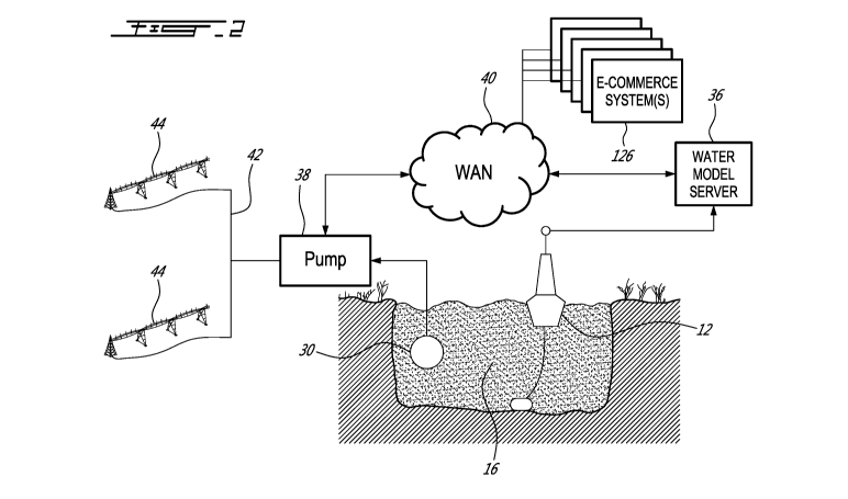
and
re-flooding of fields during cultivation, is a management practice in
irrigated fields,
typically rice paddies or the like, that saves water and reduces greenhouse
gas
emissions while maintaining yields. Existing AWD practice involves
alternatively
flooding a field and letting it dry until the water level below the soil
surface has
reached a predetermined depth, as measured through the use of a field water
tube
placed in the soil. Currently, farmers must measure the water levels in the
field water
tube manually, which can be tedious and require constant monitoring to avoid
negatively impacting their yield.
SUMMARY OF THE INVENTION
[0004] In order to address the above, there is provide a system for
providing
irrigation adjacent a watercourse having a length in which water having at
least one
of a salinity, pH, temperature and turbidity that varies over a period of time
flows.
The system comprises a communications system, a plurality of sensors each
placed
at a respective one of a first plurality of locations along the watercourse
length and
each measuring at least one of the salinity, the pH, the temperature and the
turbidity
1
CA 03073284 2020-02-18
WO 2018/045458
PCT/CA2017/051045
of the water and connected to the communication system via a wireless
connection,
a server connected to the communication system and receiving from time to time
and from each of the sensors via the communication system one of a measured
salinity, a measured pH, a measured temperature, a measured turbidity and
combinations thereof of the water at each of the first plurality of locations,
and a
plurality of pumps connected to the communication system and each comprising
an
inlet at one of a second plurality of locations along the watercourse length
wherein
the first locations are different from the second locations. The server
predicts based
on the measured salinity, the measured pH, the measured temperature and the
measured turbidity at least one of a real time salinity, a real time pH, a
real time
temperature and a real time turbidity at each of the second locations and
further
wherein when the real time salinity, the real time pH, the real time
temperature
and/or the real time turbidity at a given one of the second locations
respectively
exceeds a salinity threshold value, a pH threshold value, a temperature
threshold
value and a turbidity threshold value, a pump having an inlet at the given
second
location is disabled and when the real time salinity, real time pH,
temperature and/or
turbidity at the given one of the second locations is below the salinity
threshold
value, the pH threshold value, the temperature threshold value and the
turbidity
threshold value, the pump having an inlet at the given second location is
enabled.
[0005] There
is also provided s method for irrigating a field adjacent a
watercourse having a length and in which water having at least one of a
salinity, pH,
temperature and turbidity that varies over a period of time flows. The method
comprises placing a plurality of pumps each comprising an inlet at one of a
plurality
of pumping locations along the watercourse length, measuring from time to time
at a
plurality of measuring locations along the watercourse length at least one of
the
salinity, the pH, the temperature and the turbidity of the water wherein the
measuring
locations are different from the pumping locations, and predicting from the
measured
salinity, the measured pH, the measured temperature and the measured turbidity
at
least one of a real time salinity, a real time pH, a real time temperature and
a real
time turbidity at each of the pumping locations, and selectively disabling and
enabling a pump having an inlet at a given one of the pumping locations
dependent
on the real time salinity, the real time pH, the temperature and/or the
turbidity at the
given pumping location being respectively above or below a salinity threshold
value,
2
CA 03073284 2020-02-18
WO 2018/045458
PCT/CA2017/051045
a pH threshold value, a temperature threshold value and a turbidity threshold
value.
[0006]
Additionally, there is provided an Alternate Wetting and Drying (AWD)
method for irrigating a field using a pump comprising an outlet supplying
water to the
field and an inlet connected to a water source. The method comprises placing a
water depth sensor at a sensing location in the field, sensing using the
sensor from
time to time a water depth below a surface of the field at the sensing
location, and
transmitting the sensed water depth to a pump controller located remotely from
the
sensing location using a wireless connection. The pump controller enables the
pump
when the sensed water depth is below a threshold depth and disables the pump
when the sensed water depth is above a threshold depth.
[0007] Also,
there is provided an Alternate Wetting and Drying (AWD) system for
irrigating a field using a water source. The system comprises at least one
sensing
tube each placed at a respective location on the field, the sensing tube
comprising a
sensor for measuring a water depth below a surface of the field, at least one
pump
each comprising an inlet connected to the water source, an outlet supplying
water to
the field and a pump controller, and a wireless communication system
interconnecting each of the sensors with the pump controllers of a respective
one of
the pumps. The pump controller receives from time to time the water depth from
the
sensor via the wireless communication system, and further wherein the pump
controller enables or disables the pump in accordance with the water depth.
BRIEF DESCRIPTION OF THE DRAWINGS
[0008] Figure
1 provides a schematic diagram of an irrigation system in
accordance with an illustrative embodiment of the present invention;
[0009] Figure
2 provides a detailed schematic diagram of an irrigation system in
accordance with an illustrative embodiment of the present invention;
[0010] Figure
3 provides a schematic diagram of a salinity sensor in accordance
with an illustrative embodiment of the present invention;
3
CA 03073284 2020-02-18
WO 2018/045458
PCT/CA2017/051045
[0011] Figure
4 provides a schematic diagram of a pump assembly in accordance
with an illustrative embodiment of the present invention;
[0012] Figures
5A through 5J provide screen grabs from a hand held device used
for providing user input to the irrigation and e-commerce system in accordance
with
an illustrative embodiment of the present invention;
[0013] Figure
6 provides a schematic diagram of an Alternate Wetting and Drying
(AWD) system in accordance with an illustrative embodiment of the present
invention;
[0014] Figure
7 provides a detailed schematic diagram of an alternate wetting and
drying system in accordance with an illustrative embodiment of the present
invention;
[0015] Figures
8A provides a schematic diagram of a plurality of sensing tubes in
accordance with an illustrative embodiment of the present invention;
[0016] Figure
8B provides a schematic diagram of sensing means in accordance
with an illustrative embodiment of the present invention;
[0017] Figure
9 provides a schematic diagram of a network access point in
accordance with an illustrative embodiment of the present invention;
[0018] Figure
10 provides a schematic diagram of a pump assembly in
accordance with an illustrative embodiment of the present invention; and
[0019] Figures
11A through 110 provide screen grabs from a hand-held device
used for providing user input to the alternate wetting and drying system in
accordance with an illustrative embodiment of the present invention.
DETAILED DESCRIPTION OF THE ILLUSTRATIVE EMBODIMENTS
[0020]
Referring now to Figure 1, an irrigation system, and generally referred to
using the reference numeral 10, will now be described. The system comprises a
first
4
CA 03073284 2020-02-18
WO 2018/045458
PCT/CA2017/051045
plurality of sensor buoys 12 anchored at first locations along a length of a
watercourse 14 such as an estuary or the like along which water 16 flows from
its
source (not shown) to a river mouth 18 which empties into a body of salt water
20
such as an ocean or the like. The buoys 12 are provided with a sensor package
for
measuring salinity, pH, temperature, dissolved oxygen content (DOC) and
turbidity.
The sensed salinity, pH, temperature, DOC and turbidity of the water 16 in the
watercourse 14 varies in time and distance along the length of the watercourse
14
primarily in response to tidal conditions but also due to other conditions
such as
increased water flow due to run off and the like. In particular, the salinity
of the water
16 may vary from fresh 22 through brackish 24 to salty 26 and eventually salt
water
28 at points along the watercourse 14. The pH of the water can also effect
irrigation
and typically a slightly acidic value of between pH 5.5 and pH 6.5 is sought
after.
Additionally, a basic pH can cause sedimentation of salts which can clog
irrigation
equipment. Fertilizers can be added to the lands being irrigated to adjust the
pH.
DOC may be measured as a ratio of the measured oxygen in the water versus the
maximum amount of oxygen the water can hold. Alternatively DOC can be measured
in milligrams per litre (mg/I), moles per cubic metre (mol 02/m3) or parts per
million
(ppm) or the like. Of note is that dissolved oxygen concentration measurements
may
be affected by temperature, pressure and salinity which should be accounted
for.
The amount of Turbidity is typically a reflection of the amount of solids
suspended in
the water and can be measured as Nephelometric Turbidity Units (NTU).
[0021] Still
referring to Figure 1, a second plurality of pumps (not shown) having
inlets 30 are distributed at second locations along a length of the
watercourse 14.
Each pump is additionally connected to an irrigation network 32 which irrigate
one or
more fields 34 when the pump is enabled using water collected via their
respective
inlets.
[0022]
Referring now to Figure 2, the readings of each sensor buoy 12, and as
will be discussed in more detail below the location of the sensor buoy 12 and
the
time when the reading was taken, are illustratively received from time to time
at a
water model server 36 and a model of the salinity, pH temperature and/or
turbidity of
the water at any particular point along the watercourse 14 derived therefrom.
In this
regard, and as will be discussed in more detail, the readings can be collected
via a
CA 03073284 2020-02-18
WO 2018/045458
PCT/CA2017/051045
communication system. In particular, the model is used to predict the real
time
salinity, pH temperature and/or turbidity at the location of each of the
inlets 30. The
real time salinity, pH, temperature and/or turbidity is illustratively
provided to one or
other of the pump assemblies 38 via a broadband communication system 40 such
as
a Wide Area Network (WAN), for example the Internet. As discussed above, each
of
the pump assemblies 38 supplies an irrigation network 32 comprising, for
example
irrigation ditches or sprinklers or the like, or other equipment such as
piping 42 and
pivots 44. Typically, there are many more pump assemblies 38 than sensor buoys
12
and such that the readings from a given sensor buoy 12 will typically effect
the
operation of a number of pump assemblies 38.
[0023] Still
referring to Figure 2, a variety of modelling approaches may be
applied to predict the real time salinity, pH, temperature, DOC and/or
turbidity at the
location of each of the inlets 30 based on the readings of each sensor buoy
12. In
particular, in a particular embodiment features such as the speed of water
flow,
which is locally influenced by inter alia the depth and the width of the
watercourse,
are taken into account.
[0024]
Referring now to Figure 3, the sensor buoy 12 comprises a probe 46
controlled by a microprocessor (CPU) 48 which illustratively measures the
electrical
conductivity (EC), the pH, the temperature and/or the turbidity of the water
16. As
known in the art, the EC of water increases as the amount of salt dissolved in
the
water increases. If water forms part of the electrical circuit, the EC is
measured as
Siemens, which is the reciprocal of resistance measured in ohms. Typically,
using
programs settings stored in a Read Only Memory (ROM) 50 and/or a Random
Access Memory (RAM) 52, readings of the variable conductivity are converted
into a
measured salinity by the CPU 50, for example using a look up table or formula
also
stored in the ROM 50 and/or RAM 52 or the like which provides a conversion of
EC
into total dissolved salts (TDS), measured as parts per million (ppm)
measurement of
the amount of salt dissolved in the water. Similarly, the pH of water changes
with the
hydrogen-ion concentration and can be measured as a difference in electrical
potential between a pH electrode and a reference electrode (both not shown).
As
discussed above, the sensor buoy 12 may also comprise a thermometer, DOC
sensor and turbidity sensor (also not shown). A Global Positioning System
(GPS)
6
CA 03073284 2020-02-18
WO 2018/045458
PCT/CA2017/051045
module 54 comprising an antenna 56 can also be provided in the system to
provide
a location of the sensor buoy 12 as well as a universal clock. As also
discussed
above and with additional reference to Figure 2, from time to time the
measured
salinity, pH, temperature, DOC and/or turbidity is transmitted to the salinity
mode
server 36 via a communication system, illustratively wirelessly via a digital
cellular
telephone network such as LTE 58 and its associated antenna 60 or Short
Messaging Service (SMS) or the like. The measured salinity, pH, temperature
and/or
turbidity can also be combined with the GPS coordinates of the sensor buoy 12
as
well as a time stamp of the time when the transmitted measured salinity took
place.
In order to provide power to the sensor buoy 12, a storage battery and
replenishing
solar panel (both not show) or the like is provided.
[0025] Referring now to Figure 4, the pump assembly 38 comprises a pump 62,
illustratively a centrifugal pump comprising an inlet pipe 64 connected to the
inlet 30
and an outlet pipe 66 connected to the irrigation network 32. The pump 62 is
driven
by an electric motor 68 under control of a CPU 70 via a pump controller 72. A
GPS
module 74 and associated antenna 76 can be provided. Additionally, in order to
communicate with the water model server 36 via the WAN 40, for example,
wireless
communications such as those enabled by a digital cellular telephone network
such
as LTE 78 and its associated antenna 80 is provided. In order to provide power
to
the pump assembly 38, a storage battery and replenishing solar panel (both not
show) or the like may be provided. In particular cases, the pump assembly 38
may
also be connected to mains power.
[0026] Still referring to Figure 4, in particular the tolerable salinity
for irrigation
varies with the type of crops being grown, the type of fertilizers used as
well as the
type of soil. For example, almonds are typically very sensitive to salt while
sunflowers tolerate salt well. Additionally, crops at different stages of
plant growth
may better tolerate salinity (germinating seeds, for example, are typically
affected
more by salinity than the mature plant). Climatic conditions can also have an
effect
as high evaporation rates on hot and/or windy days may lead to evaporation and
higher salinity in the remaining water. Finally, the duration of the
irrigation cycle may
also have an effect, as well as the type of irrigation (for example drip
irrigation
typically allows a higher salinity water to be used). In view of this, and in
order to
7
CA 03073284 2020-02-18
WO 2018/045458
PCT/CA2017/051045
capture some specific details regarding the particular characteristics of the
type of
irrigation, crops, soil, fertilizers and the like being irrigated, a near
field
communications system such as a blue tooth module 82 and associated antenna 84
may also be provided. Using a hand held user device 86 such as a smart phone,
tablet or the like, and a water monitor application 88, typically downloaded
from an
appstore or the like (not shown), the user may adjust the pump control
parameters in
order to customize pump operation in accordance with the exigencies of the
local
operating environment.
[0027] Still
referring to Figure 4, the CPU 70 controls the pump 62 using
programs and user settings stored in a ROM 90 and/or RAM 92 as well as the
salinity model, or relative portions thereof, received from the water model
server 36
via LTE 78. A variety of different control methods are foreseen. In a first
embodiment
if the salinity model indicates the salinity at the location of the inlet 30
is above the
maximum salinity, the pump 62 is disabled and if the salinity at the location
of the
inlet 30 is below the maximum salinity the pump 62 is disabled. When enabled,
the
pump 62 may pump according to the local control parameters.
[0028]
Referring now to Figure 5A, in order to access the application 88 running
on a tablet, smartphone or the like, the user first selects the application
causing a
login page 94 to be displayed. In order to login, the user selects the "Log
in" button
96 while providing a registered name 98 and password 100. If the user has yet
to be
registered, the user can register with the system by selecting the "Register"
button
102. Referring to Figure 5B in addition to Figure 5A, selecting the "Register"
button
102 displays an account registration page 104 via which the user can enter
name, e-
mail and the like in order to register for an account. Once logged into the
system, the
user can select by swiping or via a menu or the like one of a plurality of
different
views. Referring to Figure 5C, for a given pump assembly 38 the user can
display a
water demand page 106 via which the user can provide a target water demand 108
as well as salinity limits 110. Referring to Figure 5D, using the list sensor
node page
112, the user can conveniently display the location of sensor buoys 12 on a
map
114. Referring to Figures 5E through 5G, water salinity, pH, temperature and
turbidity can be displayed for a given pump assembly 38 and/or sensor buoy 12
for a
selected period time. Illustratively a daily page 116 (Figure 5E), a monthly
page 118
8
CA 03073284 2020-02-18
WO 2018/045458
PCT/CA2017/051045
(Figure 5F) and a yearly page 120 (Figure 5G) are shown. Illustratively, for
the
selected time period a salinity chart 122 and a temperature chart 124 are
provided
for displaying respectively water salinity and water temperature over the
selected
time period. Similarly, a pH chart and turbidity chart.
[0029] Referring back to Figure 2, in a particular embodiment at least one
E-
commerce system 126 may be provided which communicate using the WAN 40.
Referring now to Figure 5H, a page detailing the water pumped 128 is provided
detailing the total consumption 130 for the time period 132 by the pump or
node in
question. The time 134 of pumping may also be provided. Additionally, the user
is
displayed various icons 136 which detail products available from the E-
commerce
systems 126. These can include, for example, fresh foods 138 or agricultural
materials 140 such as fertilizers or the like. Referring to Figure 51,
graphics 142
depicting products 144 for purchase via the e-commerce system may be displayed
as well as appropriate graphical controls 146 to migrate between different
products.
Selecting the agricultural materials icon 140, for example, provides an
agricultural
products page 148 illustratively displaying different fertilizers 150.
[0030] Referring now to Figure 6, an alternate wetting and drying (AWD)
system,
generally referred to using the reference numeral 152, will now be described.
The
system 152 comprises at least one sensing tube 154 placed at a respective
location
on one or more fields 156 such as rice paddies or the like and at least one
network
access point 158 in communication with the sensing tubes 154. Each sensing
tube
154 is provided with sensing means (not shown) for measuring the water depth
beneath a surface of the field 156. The water depth beneath the surface of the
field
156 varies in response to various factors such as temperature, humidity,
precipitation, flooding and irrigation. In particular, at least one pump
assembly 160
drawing water from a water source 162 such as a river is connected to an
irrigation
network 164 which irrigates the fields 156 when the pump assembly 160 is
enabled,
thus increasing the water depth beneath the surface of each field 156.
[0031] Referring now to Figure 7, the water depth readings from each
sensing
tube 154 are sent via an antenna 166 to the nearest network access point 158,
as
will be discussed in further detail below. The readings can then be collected
via a
9
CA 03073284 2020-02-18
WO 2018/045458
PCT/CA2017/051045
communication system 168 such as a Local Area Network or Wide Area Network
(LAN/WAN). As will be discussed in further detail below, when the water depth
reading from a given sensing tube 154 falls below a predetermined value,
suggesting
that the field 156 has been dried out sufficiently, the communication system
168
communicates with the at least one pump assembly 160 via an antenna 170 to
enable the pump assembly 160. The pump assembly 160 may then draw water from
the water source 162 and pump the water through the irrigation network 164,
comprising for example irrigation ditches or sprinklers or the like, in order
to flood the
field 156, and thus increasing the water level below the surface of the field
156, as
reflected by the measurements in the sensing tube 154. This alternation
between
drying and flooding reduces the amount of water needed for cultivation while
maintaining yield rates.
[0032]
Referring now to Figure 8A in addition to Figure 7, each sensing tube 154
comprises sensing means 172 for measuring the water depth 174 beneath a
surface
176 of the field 156. In an embodiment, the sensing means 172 comprises a
float
activated recording device that senses changes in water level by the movement
of a
weight-balanced float (not shown) that is lowered into the sensing tube 154.
As it is
known in the art, the water depth 174 beneath the surface 176 fluctuates with
the
flooding and subsequent drying of the field 156 and corresponds to a wet soil
level
178 underneath the surface 176 of the field 156. In order to maintain yield
rates while
saving as much water as possible, the wet soil level 178 must not drop below a
predetermined value, for example fifteen (15) centimeters beneath the surface
176.
Thus, the sensing means 172 sense when the water depth 174 reaches the
predetermined depth during the drying phase in order to enable the pump
assembly
160 to being the flooding phase.
[0033]
Referring now to Figure 8B in addition to Figure 7, the sensing means 172
are controlled by a microprocessor (CPU) 180 which measures the water depth
174
inside the sensing tube 154 using programs stored in a Read Only Memory (ROM)
182 and/or a Random Access Memory (RAM) 184. The measured water depth is
transmitted to the nearest network access point 158 via Near Field
Communication
(NFC) 186, such as Bluetooth or WiFi, and an antenna 166. In order to provide
power to the sensing tube 154, a storage battery and replenishing solar panel
(both
CA 03073284 2020-02-18
WO 2018/045458
PCT/CA2017/051045
not shown) or the like is provided.
[0034]
Referring back to Figure 8A in addition to Figure 2, as fields 156 often
occupy large areas of land of varying conditions, it may be common to find
varying
wet soil levels 178 along a given field 156. Thus, in an embodiment, the
system 152
comprises a plurality of sensing tubes 154 placed along a given field 156 in
order to
measure the water depth 174 at a plurality of locations.
[0035]
Referring now to Figure 9 in addition to Figure 7, each network access
point 158 is controlled by a CPU 188 using programs stores in a ROM 190 and/or
RAM 192. The network access point 158 receives the measured water depth from
the various sensing tubes 154 via NFC 194 and an antenna 196. A data store 198
may be provided for storing previously recorded measured water depths. In an
embodiment, a hand held user device and water monitoring application (both not
shown) may also connect to the network access point 158 via NFC 194 and
antenna
196 to consult previously recorded measured water depths. A Global Positioning
System (GPS) module 200 comprising an antenna 202 may also be provided in the
network access point 158 to provide a location of the network access point 158
as
well as a universal clock. As discussed above, the measured water depths are
transmitted to the communication system 168 via communication means,
illustratively wirelessly via a digital cellular telephone network such as LTE
204 and
its associated antenna 206 or Short Messaging Service (SMS) or the like. The
measured water depth may also be combined with the GPS coordinates of the
network access point 158 as well as a time stamp of when the transmitted
measured
water depth took place. In order to provide power to the network access point
158, a
storage battery and replenishing solar panel (both not shown) or the like is
provided.
[0036]
Referring now to Figure 10 in addition to Figure 7, the pump assembly 160
comprises a pump 208, illustratively a centrifugal pump comprising an inlet
pipe 210
connected to an inlet drawing water from the water source 162, and an outlet
pipe
212 connected to the irrigation network 164 and may include, for example, a
water
meter 214 for measuring the amount of water provided using the pump 208. The
pump 208 is driven by an electric motor 216 under control of a pump controller
218
comprising a CPU 220. A GPS module 222 and associated antenna 224 may also
11
CA 03073284 2020-02-18
WO 2018/045458
PCT/CA2017/051045
be provided. Additionally, in order to communicate with each network access
point
158 via the communication network 168, communication means such as those
enabled by a digital cellular telephone network such as LTE 226 and its
associated
antenna 228 are provided. In order to provide power to the pump assembly 160,
a
storage battery and replenishing solar panel (both not show) or the like may
be
provided. In particular cases, the pump assembly 160 may also be connected to
mains power.
[0037] Still
referring to Figure 10, and as discussed above, the key variable when
operating alternate wetting and drying in the cultivation of rice is the water
level
below the surface of the field 156. In order to save water without affecting
the rice
yield, careful monitoring of the water level must be practiced. The water
level varies
with many different factors, such as temperature, humidity, precipitation, and
wind
speeds. These factors will affect the optimal duration of time for both the
wetting and
drying cycles. In view of this, a near field communications system such as a
Bluetooth module 230 and associated antenna 232 may also be provided. Using a
hand held user device 234 such as a smart phone, tablet or the like, and a
water
monitor application 236, typically downloaded from an appstore or the like
(not
shown), the user may adjust the pump control parameters in order to customize
pump operation in accordance with the exigencies of the local operating
environment.
[0038] Still
referring to Figure 10, the CPU 220 controls the pump 208 using
programs and user settings stored in a ROM 238 and/or RAM 240 as well as those
received from the communication system 168 via LTE 226 or via hand held user
device 234 running a water monitor application 236. A variety of different
control
methods are foreseen. Typically, the AWD system 152 will comprise alternating
periods of wetting and drying selected in order to meet particular agriculture
management practices. For example, extended periods of wetting increase water
consumption and the production of greenhouse gasses, while extended periods of
drying can encourage weed growth and lead to an increase damage caused by
pests and the like. Additionally, careful selection of the periods of wetting
and drying
can reduce fertilizer requirements, simplify fertilizer application and
simplify the
eventual harvesting of the crop when ripe. Using the system 152 an AWD program
12
CA 03073284 2020-02-18
WO 2018/045458
PCT/CA2017/051045
can be established to maximize these features. In a first embodiment, when
measured water depth drops below a first predetermined low value, the pump 208
is
enabled, and when the measured water depth exceeds a second predetermined high
value, the pump 208 is disabled. When enabled, the pump 208 may pump according
to the local control parameters.
[0039]
Referring back to Figures 7, 8A and 8B, in an embodiment, as the
communication system 168 receives measured water depths from various locations
on a given field 156, the communication system 168 enables the pump assemblies
160 as soon as a single sensing tube 154 provides a measured water depth below
the above-mentioned predetermined value. In another such embodiment, the
communication system 168 is provided with calculation means (not shown) for
calculating the average measured water depth from the received measured water
depths from each sensing tube 154 and then enables the pump assemblies 160
once the average measured water depth drops below the above-mentioned
predetermined value.
[0040]
Referring now to Figure 11A, in order to access the application 236
running on hand held user device 234 such as a tablet, smartphone or the like,
the
user first selects the application causing a login page 242 to be displayed.
In order to
login, the user selects the "Log in" button 244 while providing a registered
name 246
and password 248. If the user has yet to be registered, the user can register
with the
system by selecting the "Register" button 250. Referring to Figure 11B in
addition to
Figure 6A, selecting the "Register" button 250 displays an account
registration page
252 via which the user can enter name, e-mail and the like in order to
register for an
account. Once logged into the system, the user can select by swiping or via a
menu
or the like one of a plurality of different views.
[0041]
Referring now to Figure 110, the application 236 may display a water level
page 254 comprising the measured water level from a given sensing tube 154
which
is shown on a graph 256 depicting the water level 258, above or below the
surface
level 260, and the date 262 at which each measurement was recorded. The water
level page 254 is configurable to display recorded water level measurements
for a
given day 264, month 266, and year 268, with migration tools 270 for migrating
13
CA 03073284 2020-02-18
WO 2018/045458
PCT/CA2017/051045
between desired time periods. The water level page 254 may additionally
display the
ambient air temperature 272 from a location of interest such as the rice
field, and
may additionally comprise icons for setting notification alerts 274 and
navigation
through various menus 276.
[0042]
Although the present invention has been described hereinabove by way of
specific embodiments thereof, it can be modified, without departing from the
spirit
and nature of the subject invention as defined in the appended claims.
14